LDS IGBT Series User manual

IGBT
SERIES
COMPACT INVERTER
1PHASE INVERTER
WITH 150% OVERLOAD PROTECTION
MODEL NO IGBT - K100 IGBT - K200
Motor Rating (maximum)
25W ~ 120W (1/6HP) 25W ~ 200W (1/4 HP)
Rated Output Capacity
0.4kVA 0.6kVA
Rated Output Current
1 Amp 1.5 Amp
Rated Output Voltage
AC 3 Phase 220V (3Ø220V)
Range of Output Frequency
0.1Hz ~ 400Hz
Power Source Voltage
AC 1 Phase 200V~240V (1Ø), 50Hz/60Hz
Input Current
2 Amp 3 Amp
Permissible AC Power Source Fluctuation
200V ~ 240V, 50Hz/60Hz, ±5%
Overload Protection
150% of rated output current for 1 minute
Cooling Method
Self-cooling
Protection Level
IP20
Dimension
Body 52 x 127 x 60mm • Mounting Frame: 60
x 100 x 3mm
Weight
0.4KG
Options
With Braking Transistor / Without Braking Transistor
Remark
Product dimension and mounting compatible with
US Type Speed Controller (US61-US62 / US71-US72)
The compact IGBT inverter is especially advantageous for standard application by
virtue of its user friendliness. It offers simple and safe operability, energy saving,
compact design as well as superior performance. The inverter is use in numerous
application such as conveyor drives, feeders, machining tool and door drives. It is
compactible with Unit Type AC Speed Controller (US series).
OPERATION PANEL
Start
Stop
• Reset
Up
• Down
Enter or Exit
the Function Mode
Set
• Switch
Monitor Mode
Switch Function
•
Group
• Number
Special Function
Key
Status Display I
Indicator : Frequency • Voltage •
Current • Operation
Status Display II
Power Indicator •
SPEC • START Key Indicator
Main LED Display (high brightness)
Display of Setting & Error Code
Potentiometer / Knob
Fast Setting and Input
Function Key
RUN
STOP
RESET
PROG
FUNC
DATA
<<
SPEC
P 1

Control
Method:
Voltage vector sinusoidal PWM control
(V/F control)
Switching frequency : 800~16kHz
Frequency
Range:
0.1Hz ~ 400.00Hz
Resolution:
Digital Command : 0.01Hz
•
Analogue Command: 0.06Hz / 60Hz
Overload
Protection:
150% of rated output current for 1
minute
DC Braking:
Start/Stop Braking Time:
0
~ 60.0 second •
Stop
Braking Frequency :
0.1Hz
~ 60Hz •
Braking
Ability: 0~150% of rated
current
Braking
Torque:
Approximately 20%
V/F Pattern:
Linear, Energy
-
Saving mode (automatic
adjusting V/F pattern according to the
load condition)
•
Square of 1.5, 1/7 and 2 curves.
•
V/F pattern (2 V/F points)
•
Output voltage adjustment of V/F
pattern
•
(Variable voltage adjustment of V/F
pattern for acceleration and
deceleration).
Other
Functions:
Automatic operation for energy
-saving •
Automatic torque compensation
•
Automatic adjustment for output voltage
stability
•
Automatic adjustment of switching
frequency
•
Slip compensation / Counter function
•
Restart after instantaneous power
failure
•
Modbus (RS
-485) communication •
Over
-torque detection • Jump frequency
•
Setting for upper
and lower limits of
output frequency
•
8
-preset speeds • S-curve acceleration &
deceleration
•
Temperature management
• Parameters
duplication
Frequency
Setting
Signal:
Operation panel (including KP
-601A
keypad):
Analogue Signal: (DC 0 ~ 10V) /
0~100%
Digital Signal: Jog speed, 8
-
preset speeds
Modbus (RS485) Communication
Operation
Signal:
Operation panel (including KP
-601A
keypad):
RUN / STOP
•
Digital Signal: FWD (forward) /
REV (reverse) rotation control
•
Modbus (RS
-485) communication
Multi
-
Function
Inputs:
3 programmable input terminal: X1~X3
•
Response time (1~255, unit 1ms)
•
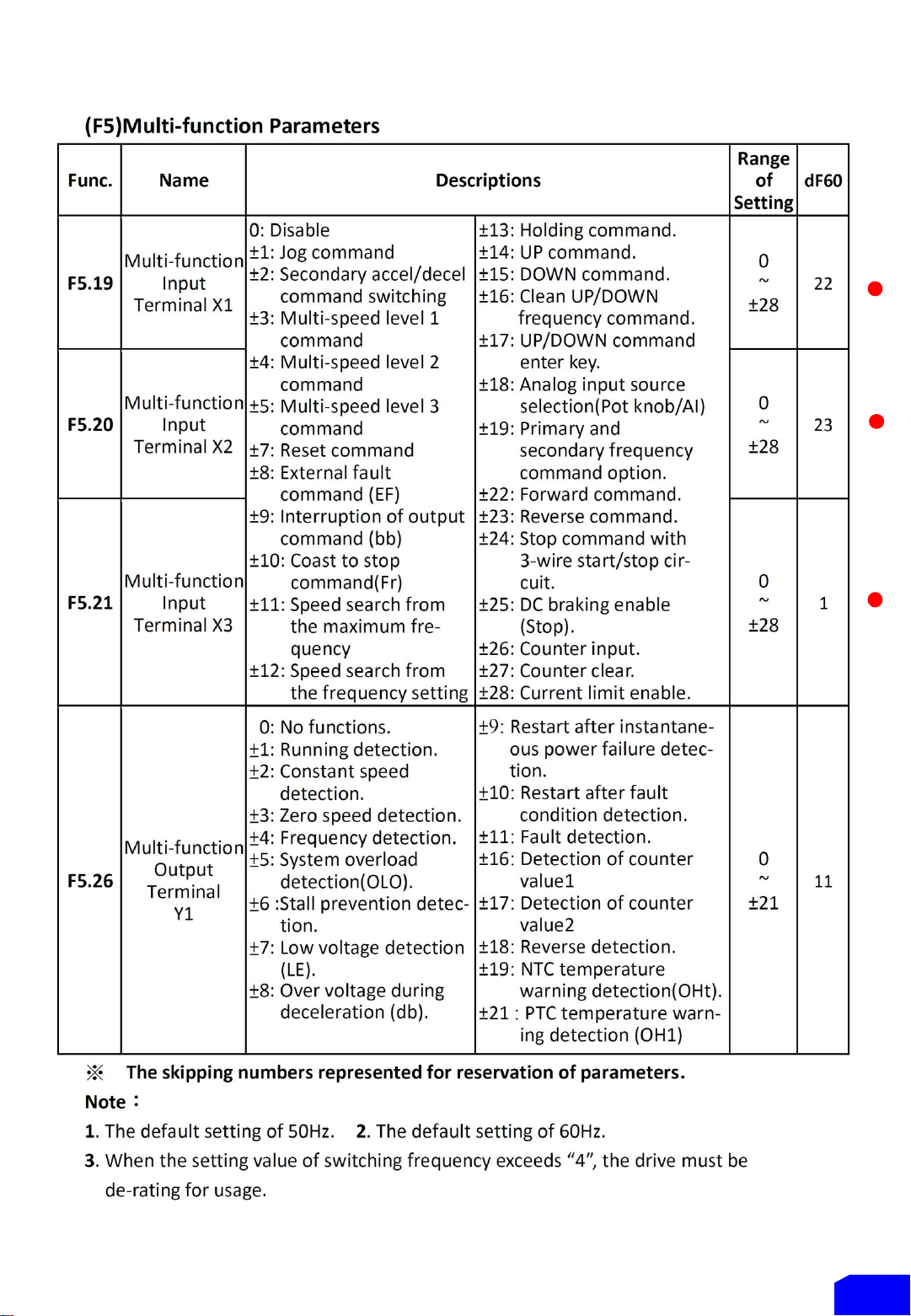
Refer to the F5.19~F5.21 functions setting
description.
Analogue
Inputs:
1 set of analogue input: VI (DC 0 ~ 10V) •
Analogue filter (0~255, unit 5ms), the
dead band of analogue frequency, gain
and bias are adjustable
GENERAL SPECIFICATIONS / CONTROL CHARACTERISTICS
The keypad
Enable remote control of
the inverter via Modbus
(RS485) Communication.
Duplication of parameter
from Inverter to Inverter.
PORTABLE KEYPAD
FG
AC Power Source
1Φ200V~240V
Motor
3Φ220VAC
L1
L2
U
V
W
MAIN CONTROL CIRCUIT
TERMINALS
Acrylic Protective
Cover
P 2

Main Circuit Terminals
Control Circuit Terminals
Modbus Port (RS-485)/ Keypad-601A
Type Symb
ol
Function Description
Terminal of Main
Circuit
Power
Source L1,L2 AC power source input
terminals
For the single-phase power
source AC 200~240V.
Motor U,V,W Drive outputs to motor
terminals
The terminals output three
phase variable frequency and
voltage to motor.
Grounding Grounding terminal Grounding resistance must be
below 100Ω
Type Sym-
bol Function Description
Control Circuit Terminal
Multi-
function
input
terminal
X1 Input terminal 1
The function is set by
F5.19~F5.21.
X2 Input terminal 2
X3 Input terminal 3
Multi-
function
output
terminal
Y1 Output terminal 1 Capacity: DC 48V, 50mA
The function is set by F5.26.
COM Input/output common
terminal
The common terminal of
input/output control signal
Control
Power
V+ Power terminal for
control signal
DC +12V output. Maximum
supplied current is 20mA.
VI Analog input terminal DC 0~10V
GND Common terminal for
analog input control
Common terminal for control
power (V+) and analog input
terminal (AI)
Type Pin Function Description
Modbus (RS-485)/
KP-601A
Communication
1Communication transmission
terminal (DX+) Modbus (RS-485)
communication uses pin 1, 2.
2Communication transmission
terminal (DX-)
3 Power terminal of KP (+13V) Only for KP-601A linking
4 Auto-detect terminal of KP Only for KP-601A linking
5 ~ 6 Reversed Reversed
7Common ports terminal of KP
power (0V) Only for KP-601A linking
8
P 3

Preface
Thank you for using LDS Compact K-series Inverter drive. For proper operations and safety
purposes, please do read and follow the safety specific instructions in the manual before using the
product. To ensure proper operation of drive, the manual shall be placed on the top of the machine.
Furthermore, please download the completely safety information on LDS website
http://www.leaderdrives.com.
Safety Precaution
1.Don’t conduct any wiring during the system power ON to avoid the electric shock.
2.Please wait at least 5 minutes until the indicator light turn off.
3.The electronic components are sensitive to static electricity in the drive.
Please don’t put the any objects in the drives or touch the main circuit board.
4.PE terminal must be exactly grounded.
5.Don’t touch the heat sink because the temperature of heat sink may over 70°C.
6.The LDS inverter series outputs are designed to drive a three-phase motor.
Do not connect output terminals to the single-phase or use for other purpose.
7.U, V, W are the outputs of drive to the motor. Please do not connect these terminals to the power
source.
Ambient Conditions
Features
1.The drive has temperature management and setting pre-alarm level to forecast over temperature
2.RS-485 Modbus RTU communication function
3.Special function key (SPEC): Cable set (in parameter) to realize FWD/REV running, jog speed,
and other multifunction operation.
4.Built-in knob (Pot) for directly speed adjustment.
5.The switching frequency can be adjust between 800Hz ~16kHz.
6.Provide 8 sets of monitor displays. (frequency, speed, voltage, current and 13 kind of options
available)
7.Counter function.
8.To support external PTC for motor overheat protection.
9.User can connect KP-601A keypad (option) for remote control, parameters duplication and saving.
10.Detachable Buckles design for installation.
11.Six sets of fault record (fault record, current, voltage, frequency)
12.Simple parameter group and complete parameter group.
13.Parameter lock and parameter password functions.
Atmosphere Non-corrosive or non-conductive, or non-explosive gas or liquid, and non-dusty
Surrounding temperature: -10°C~+45°C (14°F~122°F) (Non-condensing and non-freezing)
Storage temperature: -20°C~+60°C (-4°F~140°F)
Relative humidity: 90% RH or less (No-condensing atmosphere)
Vibration: Less than 5.9m/sec²(0.6G)
Altitude: Less than 1000m (3280 ft.)
P 4

Chapter 1 Caution before Installation
The product has passed the strictest quality test before shipped out from the factory. However, the
product might possibly sustain minor damages due to the impact, shaking, vibration, and other
factors during the transportation. Please make sure to verify the following items after receiving this
product. If the product verification finds anything abnormal, please contact the agent immediately
for the further assistance.
(1)Check up appearance of the drive for any paint chipped off, smearing, deformation of shape, etc.
(2)Check up the operation manual whether it shortage or damage or not.
(3)Check up the drive model number is identical with the shipping label on the carton or not.
1-1 Confirmation of Appearance
Serial Number
IGBT-K200
LDS Compact IGBT Inverter 200W
OVLP 150% S/N : DM15A2V242
Input : 1Ø 200V~240V 50Hz/60Hz 3.0A
Output : 3Ø 220V 0.1Hz~400Hz 1.5A
PGM: 0201-001(AZ055891) ISO 9001 IP20
www.leaderdrives.com
Leader Mechanical
& Electrical Co., Ltd
Model Number
Product
Code
Power
(Watt)
Horse
Power
K100 125W 0.17HP
K200 200W 0.25HP
P 5
Input Power Voltage
Output Power Voltage
Control
Method:
Voltage vector sinusoidal PWM control
(V/F control)
Switching frequency : 800~16kHz
Frequency
Range:
0.1Hz ~ 400.00Hz
Resolution:
Digital Command : 0.01Hz
Analogue Command: 0.06Hz / 60Hz
Overload
Protection:
150% of rated output current for 1
minute
DC Braking:
Start/Stop Braking Time: 0 ~ 60.0 second
Stop Braking Frequency : 0.1Hz ~ 60Hz
Braking Ability: 0~150% of rated current
Braking Torque:
Approximately 20%
V/F Pattern:
Linear, Energy
-Saving mode (automatic
adjusting V/F pattern according to the
load condition)
Square of 1.5, 1/7 and 2 curves.
V/F pattern (2 V/F points)
Output voltage adjustment of V/F
pattern.
(Variable voltage adjustment of V/F
pattern for acceleration and
deceleration).
Other
Functions:
Automatic operation for energy
-saving •
Automatic torque compensation
•
Automatic adjustment for output voltage
stability
•
Automatic adjustment of switching frequency •
Slip compensation / Counter function
•
Restart after instantaneous power
failure •
Modbus (RS
-485) communication •
Over
-torque detection • Jump frequency •
Setting for upper
and lower limits of output
frequency
•
8
-preset speeds • S-curve acceleration &
deceleration
•
Temperature management
• Parameters
duplication
Frequency
Setting
Signal:
Operation panel (including KP
-601A keypad):
Analogue Signal: (DC 0 ~ 10V) / 0~100%
Digital Signal: Jog speed, 8
-preset speeds
Modbus (RS485) Communication
Operation
Signal:
Operation panel (including KP
-601A keypad):
RUN / STOP
Digital Signal: FWD (forward) / REV (reverse)
rotation control
Modbus (RS
-485) communication
Multi
-
Function
Inputs:
3 programmable input terminal: X1~X3
Response time (1~255, unit 1ms)
Refer to the F5.19~F5.21 functions setting
description.
Analogue
Inputs:
1 set of analogue input: VI (DC 0 ~ 10V)
Analogue filter (0~255, unit 5ms), the dead
band of analogue frequency, gain and bias are
adjustable
GENERAL SPECIFICATIONS / CONTROL CHARACTERISTICS

Chapter 2 Installation and Confirmation
2-1 Basic Equipment
•Correct installation can extend the lifespan of the inverter, please follow the installation
precaution.
•Do not place the drive next to the heating substance or exposure to sunlight. Due to the heat
dissipating requirement during the drive operation, the drive must keep enough space for heat
dissipation.
•Environment temperature -10°C~+45°C (14°F~122°F)
•Please install the drive with clearance space around the drive and the location of installation
shall be arrange as follow :
P 6
2-2-2 Main Circuit Terminals
2-2-3 Control Circuit Terminals
Type Symb
ol
Function Description
Terminal of Main
Circuit
Power
Source L1,L2 AC power source input
terminals
For the single-phase power
source AC 200~240V.
Motor U,V,W Drive outputs to motor
terminals
The terminals output three
phase variable frequency and
voltage to motor.
Grounding Grounding terminal Grounding resistance must be
below 100Ω

Chapter 3 Characteristics and Instructions
2-1 The Features of Control and Operation
General Specifications : Control Characteristics
Control Method: Voltage vector sinusoidal PWM control (V/F control); Switching frequency :
800~16kHz
Frequency Range: 0.1Hz ~ 400.00Hz
Resolution: Digital Command : 0.01Hz
Analogue Command: 0.06Hz / 60Hz
Overload Protection: 150% of rated output current for 1 minute
DC Braking: Start/Stop Braking Time: 0 ~ 60.0 second
Stop Braking Frequency : 0.1Hz ~ 60Hz
Braking Ability: 0~150% of rated current
Braking Torque: Approximately 20%
V/F Pattern: Linear, Energy-
Saving mode (automatic adjusting V/F pattern according to the
load condition)
Square of 1.5, 1/7 and 2 curves.
V/F pattern (2 V/F points)
Output voltage adjustment of V/F pattern.
(Variable voltage adjustment of V/F pattern for acceleration and deceleration).
Other Functions: Slip compensation / Counter function / Automatic torque compensation /
Automatic adjustment for output voltage stability / Automatic operation for
energy-saving /
Automatic adjustment of switching frequency / Restart after instantaneous
power failure /
Modbus (RS-485) communication / Over-torque detection / Jump frequency /
Setting for upper and lower limits of output frequency / 8-preset speeds /
S-curve acceleration and deceleration / Temperature management /
Parameters duplication
Frequency Setting
Signal:
Operation panel (including KP-601A keypad):
Analogue Signal: (DC 0 ~ 10V) / 0~100%
Digital Signal: Jog speed, 8-preset speeds
Modbus (RS485) Communication
Operation Signal: Operation panel (including KP-601A keypad): RUN / STOP
Digital Signal: FWD (forward) / REV (reverse) rotation control
Modbus (RS-485) communication
Multi-
Function Inputs:
3 programmable input terminal: X1~X3
Response time (1~255, unit 1ms)
Refer to the F5.19~F5.21 functions setting description.
Analogue Inputs: 1 set of analogue input: VI (DC 0 ~ 10V)
Analogue filter (0~255, unit 5ms), the dead band of analogue frequency, gain
and bias are adjustable
P 7

P 8
2-2-1 Function of Operation Panel
2-2-1 Function of Operation Panel
Light color represents for lights flashing.
•2-2-3 The description of monitor mode
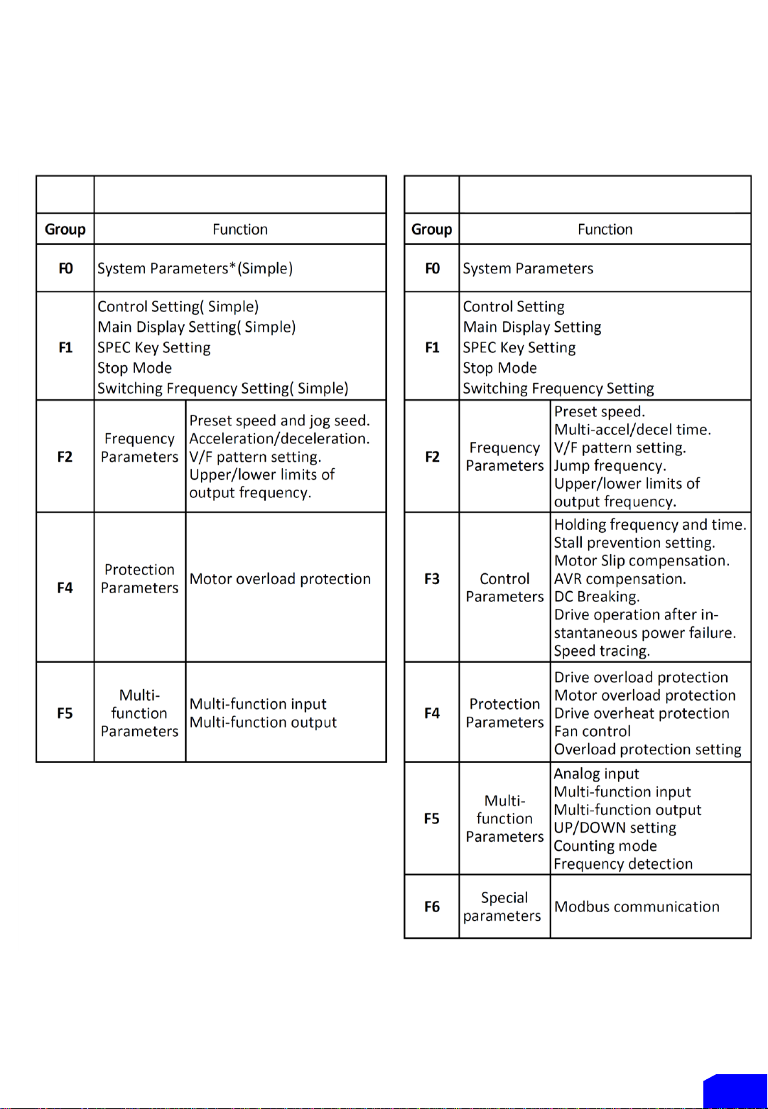
* To check the complete parameter list and communication instruction, please consult authorized distributor whom
you have bought the product from.
SIMPLE PARAMETER GROUP
(F0.18 = 0) COMPLETE PARAMETER GROUP LIST
(F0.18 = 1)
P 9
CHAPTER 3 : PARAMETER LIST
The Default Setting is Simple Parameter

P 10

(4)
P 11

P 12
P 13
P 14
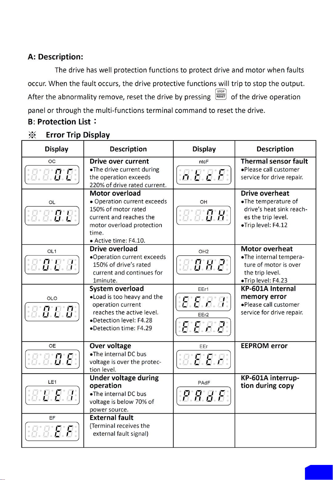
CHAPTER 4 : FAULT PROTECTION DISPLAY

P 15
CHAPTER 5 : INSTLLATION DIMENSION OF DRIVE
5-1 Outline Dimension of Drive

Purchase Accessories
1. KP-601A Keypad
2. Protection Cover for Drive
3. Inverter Mounting Bracket –Type H
(Made in Stainless Steel 304)
Please consult any LDS authorized distributor for
the accessories and specification.
Log on: www.leaderdrives.com
P 16
5-2 Installation Dimension
This manual suits for next models
2
Table of contents
Popular Inverter manuals by other brands


Lenze
Lenze 8600 series operating instructions

SMA
SMA SUNNY BOY 3600TL operating manual

Champion Global Power Equipment
Champion Global Power Equipment 200953 Operator's manual

Mastervolt
Mastervolt WHISPER 3 installation manual

Mayty
Mayty PS028 user guide

Power One
Power One AURORA Installation and operation guide


