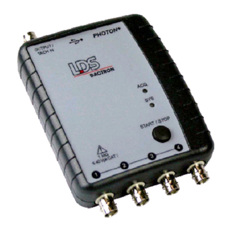
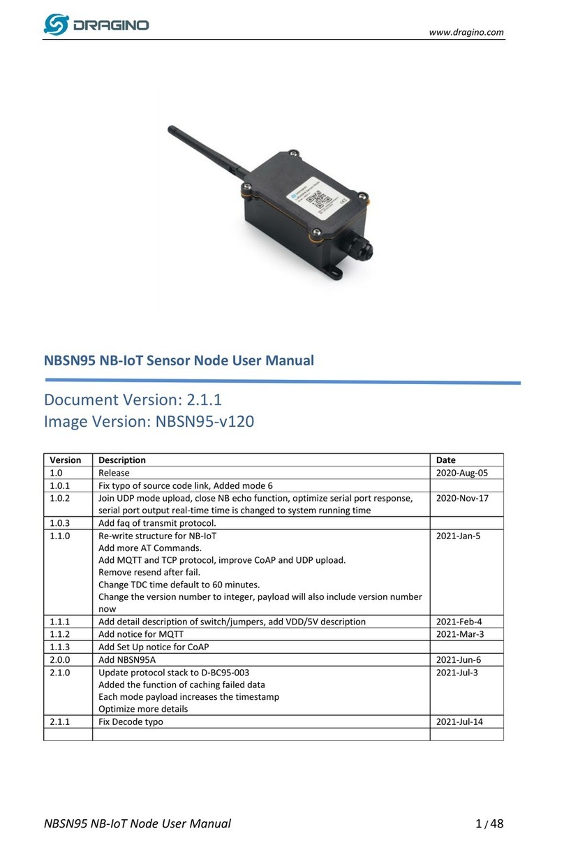
LDS Dactron FOCUS II Parts list manual

FOCUS II
Dynamic Signal Analysis System
System Guide
Rev. 3.05
System Installation
Maintenance
Calibration
Troubleshooting
LDS-Dactron
Phone. (408) 934-9160
Fax. (408) 934-9161
Web Site: www.lds-group.com

Notice
Information in this document is subject to change without notice. No part of this
document may be reproduced or transmitted in any form or by any means, electronic or
mechanical, for any purpose, without the express written permission of LDS.
LDS makes no warranties on the software, whether express or implied, nor implied
warranties of merchantability or fitness for a particular purpose. LDS does not warrant
your data, that the software will meet your requirements, or that the operation will be
reliable or error free. The user of the software assumes the entire risk of use of the
software and the results obtained from use of the software. LDS shall not be liable for
any incidental or consequential damages, including loss of data, lost profits, cost of
cover or other special or indirect damages. Your rights under law may vary.
US Government Restricted Rights
The software and documentation are provided with Restricted Rights. Use,
duplication, or disclosure by the Government is subject to restrictions as set forth in
subparagraph c(1)(ii) of the Rights in Technical Data and Computer Software clause at
DFARS 252.227-7013 or subparagraphs c(1) and (2) of the Commercial Computer
Software - Restricted Rights at 48 CFR 52.227-19 as applicable. The Manufacturer is
LDS Test and Measurement LLC, 8551 Research Way, M/S 140, Middleton, WI
53562.
Copyright ©1997-2005 LDS Test and Measurement. LDS is a member of SPX
Corporation. All rights reserved
All trademarks and registered trademarks are the property of their respective holders.

Focus II System Guide i
Table of Contents
1Introduction ........................................................................................................ 1
System Description............................................................................................... 2
Options ................................................................................................................. 3
System Hookups and Status Indicators ................................................................ 4
Specifications ....................................................................................................... 9
2Safety and Equipment Protection ................................................................... 14
Safety Summary ................................................................................................. 14
Danger Warnings................................................................................................ 15
3Power and Environmental Requirements...................................................... 16
Power Requirements........................................................................................... 16
USB Cable Requirements................................................................................... 16
Environmental Requirements ............................................................................. 17
Operation ............................................................................................................ 17
Storage and Shipment......................................................................................... 17
Packaging for Shipment ..................................................................................... 18
4System Installation ........................................................................................... 19
Step 1: Focus II Driver Installation Instructions ................................................ 19
Step 2: Installing Application Software on the PC............................................. 23
Step 3: Running the RT Pro Software ................................................................ 24
Updating the Device Driver................................................................................ 26
Uninstalling the Device Driver........................................................................... 30
5Maintenance...................................................................................................... 38
6Calibration ........................................................................................................ 39
What Do We Calibrate?...................................................................................... 39
Signal Source Used for Calibration.................................................................... 39
Calibration Tools ................................................................................................ 40
Installing the Calibration Software..................................................................... 41
Calibration Procedure......................................................................................... 42
7System Troubleshooting................................................................................... 59
USB not connected at application startup .......................................................... 60
Check if USB driver is installed correctly.......................................................... 60
Failure to initialize the Focus II ......................................................................... 61
USB cable disconnected while operating software ............................................ 62
Windows Application Software Failure ............................................................. 62
8Limited Warranty Statement .......................................................................... 63
9Manual Revision History ................................................................................. 65
10 Index .................................................................................................................. 66


Introduction
Focus II System Guide 1
1 Introduction
This manual provides instructions on installing, maintaining, and
calibrating a FOCUS II Dynamic Signal Analysis System. It also
provides information on power and environmental requirements and
safety considerations. Any person responsible for installing, maintaining
or calibrating the system should be fully familiar with the contents of this
manual. For instructions on using the system refer to the “RT Pro
Dynamic Signal Analysis Series.”
Other sections of this manual cover:
•Power and environmental requirements
•Safety
•Installation
•Maintenance
•Calibration
•Troubleshooting

Introduction
Focus II System Guide 2
System Description
Focus II makes any PC an instrument-quality analyzer that is a flexible
multi-channel system for noise and vibration analysis. Designed for real-
time signal analysis, the Focus II offers remarkable performance with a
measurement dynamic range of 120 dB and a 42 kHz real-time rate.
Signal analysis applications are available for the range of noise and
vibration testing – real-time spectrum analysis, modal data acquisition,
real-time octave analysis, data recording, order tracking, transient
capture and SRS analysis. The Focus II System comes standard with
four inputs with ICP®sensor power and TEDS capability, two output
signal sources, a 6’ (1.83 m) USB 2.0 Type A to Type B cable , a user
manual, installation CD, calibration data floppy disk, and a one year
warranty.
The Focus II has a serial bus structure and allows for modular
expansion. Board installations must be performed by an authorized
LDS-Dactron representative. The basic system is configured as 4 analog
input channels and 2 output channels. Extra inputs are added in 4-
channel increments, by purchasing FCS-201 analog input modules.
Functionality may also be added through FCS-202 strain gage and FCS-
203 thermocouple modules. Up to four additional modules can be
integrated into the Focus II chassis to build a 20-channel analog input
system or a 4-channel analog input system combined with various
configurations of strain gage and/or thermocouple inputs.
The Focus II is a USB 2.0 device. It can function with USB 1.0 and 1.1
communications however the throughput to the PC will be significantly
reduced. It is recommended that the PC be equipped with USB 2.0 or a
USB 2.0 bridge card, which converts a PCI or PCMCIA port into a USB
2.0 port.

Introduction
Focus II System Guide 3
Options
There are both hardware and software options available for the Focus II.
These options are listed in the table below.
Hardware Options Description
FCS-201 4-Channel Analog Input Module
FCS-202 4-Channel Strain Gage Module
FCS-203 4-Channel Thermocouple Module
Real-Time Software Options Description
RT Pro Signal analysis and waveform source functions
Modal Data Acquisition Compute FRF for modal analysis
Acoustic Data Acquisition Real-time octave analysis
Order Tracking and Analysis Order tracking and waterfall analysis
Environmental Data Reduction Transient capture and SRS analysis
Swept Sine Analysis Swept Sine analysis with digital tracking filters
Long Waveform Recording Gap free streaming of data to disk while
performing real-time analysis
Calibration In-house System Calibration
Post Processing Options Description
RT Pro Playback Time and frequency domain signal analysis
Acoustic Analysis Playback Post processed octave analysis
Order Tracking Playback Post processed order tracking and waterfalls
Environmental Data Reduction Post processed SRS synthesis
Sound Quality Analysis Data editing and sound quality metrics
Data Recorder Option Description
Data Recorder RT Pro data recorder with voice channel

Introduction
Focus II System Guide 4
System Hookups and Status Indicators
The front of the system chassis has between 6 – 22 connectors.
Connectors labeled 1 through 20 are for connection to input signals. The
two source connectors supply analog output signals to drive devices such
as electrodynamic shakers and acoustic speakers.
Warning
Do not connect analog voltage signals exceeding +40
Volts to the input or tachometer channels or the
system electronics may be damaged.
LED’s on the front panels provide status indication:
SYS _ flashes when the unit is powered and the hardware
code has been loaded.
ACQ – flashes when the system is acquiring data and on
otherwise.
INPUT – lit green when unit is powered on and input voltage
does not exceed the voltage range. They are lit red
when input voltage exceeds voltage range indicating
overload condition.

Introduction
Focus II System Guide 5
STRAIN – lit green when unit is powered on and input voltage
does not exceed the voltage range. They are lit red
when input voltage exceeds voltage range indicating
overload condition.
Detailed view of the Focus II Strain Gage Connector
THERMO – lit green when unit is powered on and input voltage
does not exceed the voltage range. They are lit red
when input voltage exceeds voltage range indicating
overload condition. Note also that the thermocouple
module is equipped with sensor auto-detection,
meaning that the LED’s are lit green when sensors
are attached and lit red when sensors are not
attached.

Introduction
Focus II System Guide 6
Also on the front are a USB port, an AC adaptor jack, and a power
switch. The AC adaptor jack is a standard single pin 2.1mm plug limited
to a range of 9 to 36 Volts.
On the rear of the unit is a SYNC port, which allows users to chain
together two Focus II units. This allows for channel expansion from the
standard maximum of 20 to up to 40 simultaneous channels. The SYNC
port connector is an 8 pin female mini DIN which accepts standard male
to male cables. The 8 pin mini DIN cable should be shielded and be no
longer than 2.0 ft.
Detailed view of the Focus II Sync Port
The two side panels contain cooling fans. The Focus II contains a
thermostatic sensor that automatically controls the operation of the fans.
The fans are normally off and temporarily turned on, when needed, after
a warning is displayed within the software.

Introduction
Focus II System Guide 7
The Focus II is provided with rubber shock resistant bumper guards.
These are designed to stabilize the enclosure on a desktop surface,
stabilize a laptop PC placed on top of the enclosure and protect the
system from vibration shocks. An integrated handle is available for easy
transport of the Focus II. There is also an attachable foot that allows the
Focus II to be placed in a standing “tower” position.
Horizontal arrangement of the Focus II.
Vertical (Tower) arrangement of the Focus II.
The vertical configuration is achieved by
securing the provided foot attachment.
There is also a convenient handle for
carrying the Focus II

Introduction
Focus II System Guide 8
Front view of the Focus II showing Connectors for 20 Channels, 2 Output (Source) Channels, Power
Switch, AC Adapter Jack, and USB Cable Port
Rear view of the Focus II showing the Sync Port

Introduction
Focus II System Guide 9
Specifications
Inputs
Analog Four standard, expandable to forty simultaneous channels. All are differential
inputs with 220k impedance. Each input channel has overload detection
before both the analog and digital anti-alias filters. Setup allows per channel
selection of input voltage range (0.1V, 0.3V, 1V, 3V, 10V), transducer
sensitivity, sensor type (e.g., acceleration, force, pressure, etc.), and coupling
selections for DC, AC (high pass cutoff at 0.7 Hz, 3 Hz, or 22.4 Hz defined as -
0.1dB amplitude attenuation), ICP and TEDS.
Input format Differential
Input Connector BNC
Electronics Differential amplifier, programmable gain amplifier, anti-aliasing filters, and 24
bit Analog to Digital Converter (ADC).
Filtering An analog filter plus a 160 dB/octave linear-phase digital filter prevent aliasing
and phase distortion.
Frequency range 42 kHz analysis frequency (96k samples per second).
Voltage range ±10 Vpeak
Signal conditioning Voltage, ICP sensor power (4.7 mA, 30 Vpeak open circuit), and TEDS.
Maximum input ±40 Vpeak without damage
Resolution 24-bit
Dynamic range 120 dBfs, 110 dB minimum in FFT mode
Accuracy ±0.15 dB (1 kHz sine at full-scale)
Channel Match
Amplitude
Phase
Within ±0.04 dB
Within ±0.50 degree (from DC to 21kHz, frequency response measurement,
both inputs on the same input range, linear average)
Alias protection >117 dB stopband rejection
Signal-to-noise > 100 dB (from DC to 1000 Hz measured with half-full-scale sine wave)
Cross-talk <-110 dB
Total Harmonic
Distortion + noise
<-105 dBfs
Frequency Within 0.01 %
All Specifications subject to change without notice.

Introduction
Focus II System Guide 10
Strain Gage Four channel signal conditioning module for full bridge and half bridge strain
gages, maximum of 16 simultaneous channels per unit.
Input format Differential
Input Connector 6 pin LEMO 0B
Impedance 2 MΩ, 1MΩeach pin to GND
Excitation voltage
2.5V, 5.0V, 10.0V, selectable per module
Excitation Current
50mA/Channel Max with over current protection
Input ranges 2mV, 5mV, 10mV, 20mV, 100mV
Zero Suppression ±500mV adjustment range with 65536 steps
Max. input voltage ±40Vpeak
Coupling DC or Digital AC
A/D 24 Bit
Sample rate 32 S/s to 96 kS/s
Bandwidth DC - 30 kHz
Filter Analog and Digital Anti-Alias Filters, Ripple Elimination Filter
DC Gain Accuracy 0.1% for ±100 mV input range
0.3% for ±20 mV input range
0.5% for ±10 mV input range
0.8% for ±5 mV input range
1.2% for ±2 mV input range
Offset error 100uV max.
Auto-Balance 16 bits D/A converter
Auto-Balance Limits -500mV to +500mV for all input range
Half Bridge Resistors Two precision resistors, 10k, each, 0.1% ratio matching
Shunt Calibration
Type
Two independent points
Shunt Resistors: 2 Resistors, 36k, 9k
Switch resistance 1.7typical, 2.5MAX,
Switch-off leakage <0.5nA @ 25 degree C, <2.5nA from 0 to 70 degree C
All Specifications subject to change without notice.

Introduction
Focus II System Guide 11
Thermocouple Four channel signal conditioning module for thermocouples, maximum of 16
simultaneous channels per unit.
Input format Differential
Input Connector Omega Miniature
Impedance 20 Mbetween input pins, 10Mbetween each pin to GND
Max. input voltage ±40Vpeak
Coupling DC
A/D 24 Bit
Sample rate 2 S/s to 96 kS/s
Applicable
thermocouple
Type: Universal (J, K currently supported)
Cold Junction
Compensation
One sensor per Channel, ±0.5 Degree C accuracy
Input Range ±9mV ±18mV ±36mV ±54mV ±72mV
J/˚C -50, 150 -50, 300 -50, 60 Not USED -50, 1200
K/˚C -50, 200 -50, 400 -50, 800 -50, 1300 Not USED
Filter Analog and Digital Anti-Alias Filters, Ripple Elimination Filter
Switch-off leakage <0.5nA @ 25 degree C, <2.5nA from 0 to 70 degree C
DC Gain Accuracy Input Range ±9mV ±18mV ±36mV ±54mV ±72mV
Offset <0.4% <0.2% <0.1% <0.1% <0.1%
DC accuracy was tested with ambient temperature of 23 °C ±3 °C, ambient humidity of 55 % ±10 %,
after calibration, following a 30-minute warm-up period.
Temperature Accuracy ±(3 ˚C +Gain Accuracy * Full Input Range)
All Specifications subject to change without notice.

Introduction
Focus II System Guide 12
Outputs
Analog Waveform Source with 2 channels standard
Output connector BNC
Electronics 24-bit Digital to Analog Converter (DAC) with analog and digital anti-imaging
filters.
Filtering A 160 dB/octave digital filter plus an analog filter prevent imaging and phase
distortion.
Frequency range Up to 42 kHz output frequency (96k samples per second) with extended
frequency option.
Voltage range ±10 Vpeak
Resolution 24-bit
Dynamic range 120 dBfs
Total Harmonic
Distortion
< -95 dBfs
Output impedance 50
Maximum current 500 mA peak
Hardware
Enclosure Aluminum and steel case encloses low-noise input/output modules with
multiple 75 MHz 32-bit floating-point DSP processors. Rubber bumper guards
for shock protection and stabilization. Front panel – Bi-color status LEDs,
power switch, USB connector, and AC adaptor jack. Back panel – sync port
Input expansion From four up to forty total inputs.
PC configuration PC with USB connector, Windows 2000/XP Operating System, and Microsoft
Word are the only requirements.
PC expansion PC upgrades and peripheral additions do not delay or interrupt data acquisition
and realtime processing.
General
Mains Power 9 - 42 Volts DC
Power Consumption 20 – 35 Watts
Dimensions
Height
Width
Depth
4.5 in. (11.4 cm)
11.25 in (28.6 cm)
10.5 in. (26.7 cm) (dimensions include bumper guards)
Weight 13.5 lbs. (5.85 kg)
Temperature 32 to 122 ºF (0 to 50 ºC)
Humidity 10% to 90% RH non-condensing
All Specifications subject to change without notice.

Introduction
Focus II System Guide 13
Regulatory Compliance
Compliance CE1Marking
Safety EN260950-1, IEC360950-1
EMC FCC4Part 15 (CFR 47) Class A, EN 61326 Class A, CISPR225
Class A
1CE = European Compliance.
2EN = European Norm.
3IEC = International Electrotechnical Commission.
4FCC = Federal Communications Commission.
5CISPR = International Special Committee On Radio Interference.
European Community Statement
This equipment complies with the following European directives:
EMC Directive 89/336/EEC and amending Directives 92/31/EEC and 93/68/EEC Low Voltage
Directive 73/23/EEC.
FCC Class A Statement
This equipment has been tested and found to comply with the limits for a Class A digital device,
pursuant to Part 15 of the FCC Rules.
These limits are designed to provide reasonable protection against harmful interference when
operated in a commercial environment.
This equipment generates, uses, and can radiate radio frequency energy and, if not installed and
used in accordance with the instruction manual, may cause harmful interference to radio
communications.
Operation of this equipment in a residential area is likely to cause harmful interference, in which
case, the user will be required to correct the interference at his own expense.
Any changes or modifications to this equipment not expressly approved by LDS-Dactron could
void the user's authority to operate this equipment.
All Specifications subject to change without notice.

Safety and Equipment Protection
Focus II System Guide 14
2 Safety and Equipment Protection
Safety Summary
The following general safety precautions must be observed during all
phases of operation, maintenance, and calibration of this system.
Failure to comply with these precautions or with specific warnings
elsewhere in this manual violates safety standards and/or design,
manufacture, and intended use of this system. LDS-Dactron
assumes no liability for the customer’s failure to comply with these
requirements.
Do Not Operate In an Explosive Atmosphere
Do not operate the system in the presence of flammable gases or fumes.
Operation of any electrical instrument in such an environment constitutes
a definite safety hazard.
Keep Away From Live Circuits
Operating personnel must not remove the system cover. Qualified
service personnel must make component replacement and internal
adjustments. Do not replace components with power cable connected.
Under certain conditions, dangerous voltages may exist even with the
power cable removed. To avoid injuries, always disconnect power and
discharge circuits before touching them.
Do Not Substitute Parts or Modify the System
Because of the danger of introducing additional hazards, do not install
substitute parts or perform any unauthorized modification to the system.
Return the system to LDS-Dactron for service and repair to ensure that
safety features are maintained.

Safety and Equipment Protection
Focus II System Guide 15
Danger Warnings
The warning messages below, and throughout this guide, are important
notices regarding safe system operation and system protection.
Instructions given by these warnings must be followed to ensure safety
for both personnel and equipment.
Warning
Dangerous voltages may be present in the system. Use
the same care as you would for any electronic
equipment when handling, calibrating, or maintaining
this system.
Warning
Under no circumstances should an operator remove
any covers, screws, or in any way enter the Focus II
System. There are no operator settable controls or
adjustments inside the Focus II.
Warning
To prevent potential fire or shock hazard, do not
expose the system to rain or moisture.
Warning
Do not connect analog voltage signals exceeding +40
Volts to the input or tachometer channels or the
system electronics may be damaged.
Warning
Do not connect an analog voltage source to the
output channel or the system electronics may be
damaged.

Power and Environmental Requirements
Focus II System Guide 16
3 Power and Environmental
Requirements
Power Requirements
The Focus II requires a DC source with a voltage between 9 and 36
Volts DC. This is provided by the external AC to DC adaptor supplied
by LDS-Dactron or from any DC power source including an optional
battery pack available from LDS-Dactron.
The Focus II consumes between 20 and 35 Watts depending on the
number of channels and sources activated. It is recommended that the
external AC to DC adaptor be rated at 72 Watts to provide a factor of
safety and adequate power for any start-up surges.
USB Cable Requirements
It is recommended that a USB 2.0 cable be used with the Focus II. Note
USB 2.0 cables are typically of higher quality than USB 1.0 or 1.1
cables. The exterior of the cable should be marked as USB 2.0.
The maximum USB cable length is 16 feet. Additional USB cables can
be added to increase the length provided that a powered USB hub is
added between cables. A USB Repeater Cable may be used as an
alternative to a powered USB hub.
Table of contents
Other LDS Measuring Instrument manuals
Popular Measuring Instrument manuals by other brands
SensaTronics
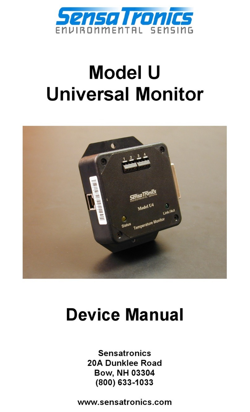
SensaTronics U Device manual
Endress+Hauser
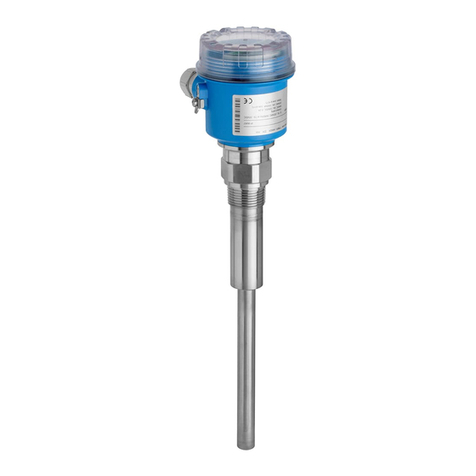
Endress+Hauser Soliphant T FTM20 technical information
Omega
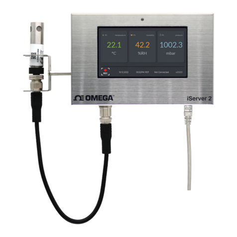
Omega iServer 2 Series user guide
Spectrum Technologies
Spectrum Technologies LightScout 3415Z product manual

Ivoclar Vivadent
Ivoclar Vivadent bluephase operating instructions
HW Group
HW Group NB Series manual

