LEAD energy PDC Series User manual

BEDIENUNGSANLEITUNG
OPERATING MANUAL
MANUEL D‘UTILISATION
HANDLEIDING
BRUKSANVISNING
NÁVOD K OBSLUZE
NÁVOD NA POUŽITIE
INSTRUCȚIUNI DE UTILIZARE
VERSION 3.0 - 03/17
LED PANEL DYNAMIC COLOR
PDC
PDC30 Art.Nr 70200029
PDC62 Art.Nr 70200028


PDW 30 289 x 289 mm
PDC 62: 609 x 609 mm
DEUTSCH
Vielen Dank, dass Du Dich für ein Produkt der LEAD
energy AG entschieden hast. Falls Du unseren
Service erreichen möchtest, sind wir für Dich auf
unserer Homepage und per E-Mail erreichbar.
service@lead-energy.com
www.lead-energy.com
?
Bestimmungsgemäße Verwendung
Du kannst die Panel PDC in Rasterdecken einbau-
en oder sie mit optional erhältlichem Zubehör als
Deckenaufbauleuchte oder abgehängte Leuchte
montieren.
Hinweis
Beachte vor der Installation zwingend die beiliegenden
Warnhinweise!
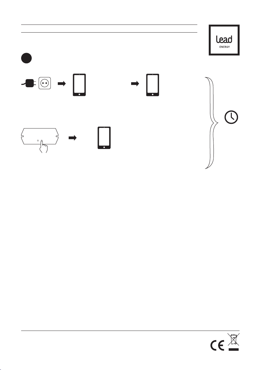
Beachte, dass der WLAN-Controller Deiner
Leuchte zur Konfiguration des Produkts zugäng-
lich sein muss. Du kannst Deine Leuchte auch vor
der Montage konfigurieren. Die Einstellungen blei-
ben auch nach dann erhalten, wenn Du die Strom-
versorgung trennst. Notiere Dir die SSID und das
Passwort des WLAN-Controllers.
Montage in Rasterdecken
1.1
Montage
1
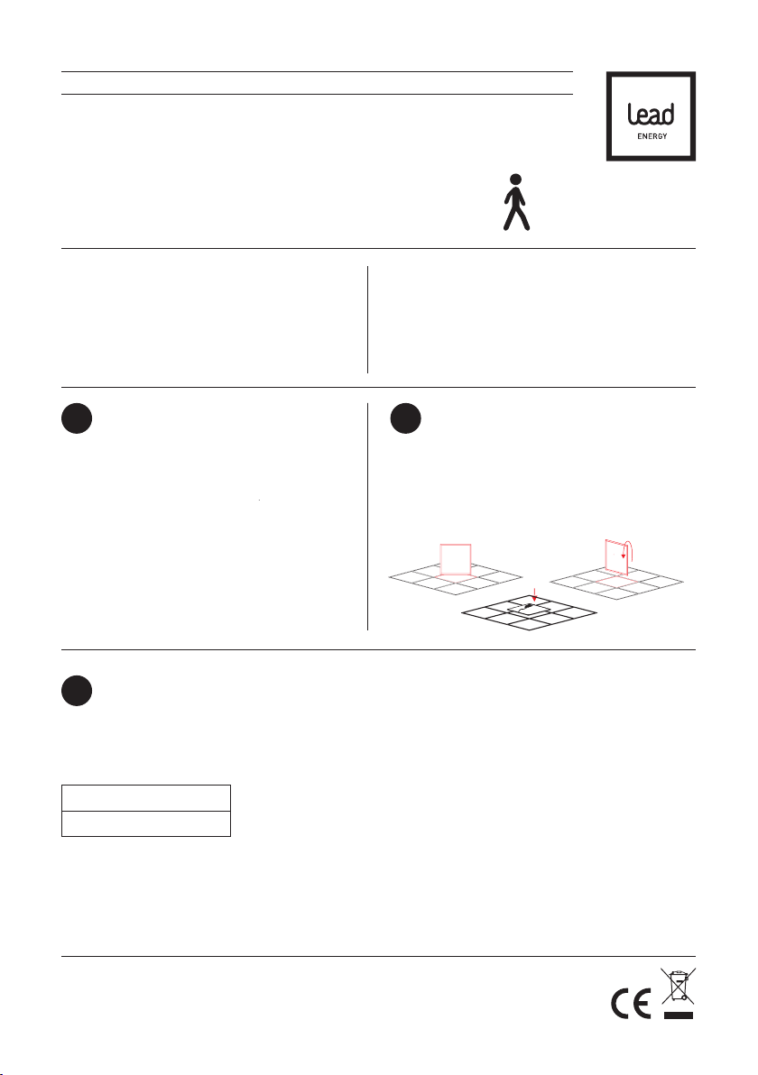
Du kannst Dein PDC in Rasterdecken einbauen, indem
Du eine Deckenplatte durch das Panel ersetzt. Die
Größe der Deckenplatte muss dabei unbedingt der
Größe des Panels entsprechen.
Montage in abgehängten Decken
1.2
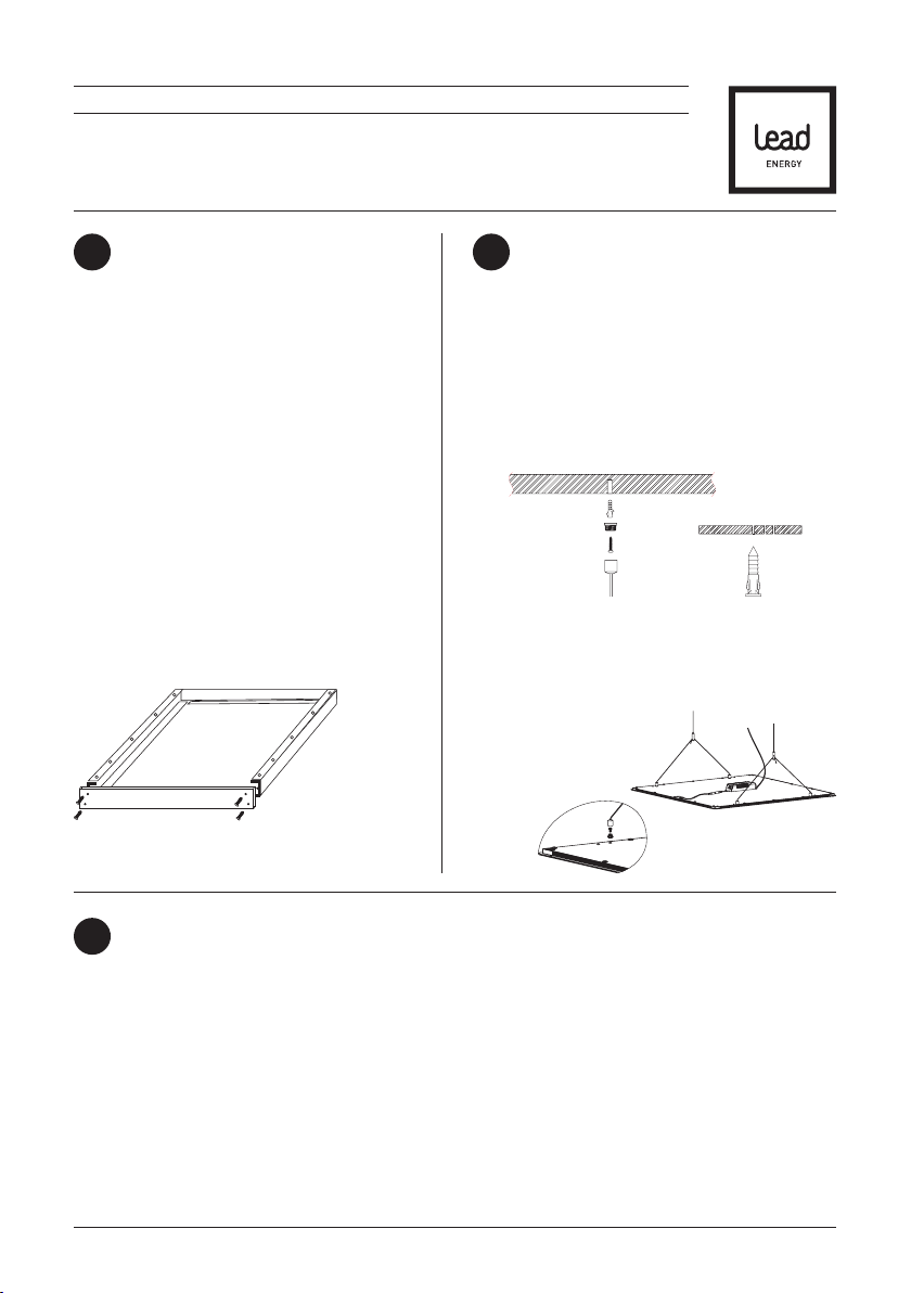
Befestige die beiliegenden Federhalter mit den Schrauben an Deinem Panel. Stelle einen Deckenausschnitt her;
die Größe des Ausschnitts kannst Du der folgenden Auflistung entnehmen:
Den Ausschnitt musst Du sehr präzise ausführen. Die Ränder des Ausschnitts müssen das Gewicht der Leuchte
tragen können. Stelle in der Decke den elektrischen Anschluss des Netzkabels her. Setze das Panel in den Decke-
neinschnitt ein, indem Du die Federhalter zurück drückst. Gehe sicher, dass das Panel vollständig eingerastet ist.
„Hiermit erklärt LEAD energy AG, dass sich das Gerät dieses Gerät in Übereinstimmung mit den grundlegenden
Anforderungen und den übrigen einschlägigen Bestimmungen der Richtlinie 1999/5/EG befindet.“
Die vollständige Konformitätserklärung findest du hier: https://www.lead-energy.com/innen/panel-einlegeleuchten/
LEAD ENERGY AG Zollhof 30 40221 Düsseldorf Irrtümer und Änderungen vorbehalten Informationen/technischer Support: www.lead-energy.com

DEUTSCH
Montage als Anbauleuchte
1.3 Montage als abgehängte Leuchte mit Rahmen
1.4
Montage mit optional erhältlichem PANEL FRAME
PF (Beachte auch die Montageanleitungen des
Zubehörs).
Setze die vier Profile zusammen und verschrau-
be diese mit je vier Schrauben in den dafür
vorgesehenen Löchern an den beiden Endkappen.
Befestige den Rahmen an der Decke. Hierzu musst
Du die für Deine Decke geeigneten Befestigungs-
materialien verwenden. Löse anschließende eine
Endkappe vom Rahmen, stelle den elektrischen
Anschluss her und lege Dein Panel ein.
Verschraube nun wieder die Endkappe mit den vier
Schrauben.
Hierzu benötigst Du zusätzlich zum Rahmen ein
passendes ROPE HANGER SET.
Befestige jetzt die Montagesockel Deines ROPE
HANGER SETS an der Decke. Hierzu musst Du die,
für Deine Decke geeigneten, Befestigungsmaterialien
verwenden.
Befestige die dafür vorgesehenen Enden Deines
ROPE HANGER SETS am PANEL FRAME.
Löse anschließende eine Endkappe vom Rahmen
und lege Dein Panel ein. Verschraube nun wieder
die Endkappe mit den vier Schrauben und stelle den
elektrischen Anschluss her.
Montage als abgehängte Leuchte ohne Rahmen
1.5
Beachte auch die Montageanleitungen des Zubehörs.
1. Befestige die Montagesockel Deines ROPE HANGER SETS an der Decke. Hierzu musst Du die für Deine Decke
geeigneten Befestigungsmaterialien verwenden.
2. Befestige die Gegenstücke zu Deinem ROPE HANGER SETS am PANEL FRAME in den vorgesehenen
Bohrlöchern mit den beiliegenden Schrauben.
3. Schraube die Endstücke Deines ROPE HANGER SETs an die zuvor befestigten Gegenstücke am Panel.
4. Stelle den elektrischen Anschluss her.
LEAD ENERGY AG Zollhof 30 40221 Düsseldorf Irrtümer und Änderungen vorbehalten Informationen/technischer Support: www.lead-energy.com

O
I
WiFi
DEUTSCH
LEAD ENERGY AG Zollhof 30 40221 Düsseldorf Irrtümer und Änderungen vorbehalten Informationen/technischer Support: www.lead-energy.com
Anlernen - Fernbedienung CDC
2
innerhalb
von 15 s
2 x kurz
ANSCHALTEN
(rotes Licht
leuchtet)
innerhalb von 2 s
blinkt für 3 s
1 x lang
Strom
AN Learning Switch
1 x kurz
1 x kurz
innerhalb von 2 s
blinkt für 3 s
wischen
gegen den
Uhrzeigersinn
Alternativ:

O
I
WiFi
Anlernen - Wandcontroller WCC
2
2 x kurz
Strom
AN
innerhalb
von 15 s
innerhalb von 2 s
blinkt für 3 s
ANSCHALTEN
Learning Switch
1 x kurz
Alternativ:
1 x kurz
innerhalb von 2 s
blinkt für 3 swischen von
oben nach
unten
1 x lang
DEUTSCH
LEAD ENERGY AG Zollhof 30 40221 Düsseldorf Irrtümer und Änderungen vorbehalten Informationen/technischer Support: www.lead-energy.com

WiFi
DEUTSCH
LEAD ENERGY AG Zollhof 30 40221 Düsseldorf Irrtümer und Änderungen vorbehalten Informationen/technischer Support: www.lead-energy.com
Strom
AN
Anlernen - APP
2
LEAD DYNAMIC APP
starten
innerhalb
von 90 s
Learning Switch
1 x kurz
Über WLAN mit
LEAD DYNAMIC_xxx
verbinden
Passwort: 0123456789
Den Anweisungen
der APP folgen

WiFi
O
I
5 x
O
I
WiFi
DEUTSCH
Um alle Einstellungen Deines PANEL DYNAMIC COLOR zurück zu setzen, halte die „Learning Switch“-Taste auf
Deinem WiFi Controller für etwa 10 Sekunden gedrückt, bis Dein Panel blinkt.
Reset - Panel
3
Learning Switch
10 s
drücken blinkt kurz
Alternativ:
Strom
AUS
Strom
AN
blinkt nach 5s
innerhalb
von 10 s
Um alle Einstellungen Deines PANEL DYNAMIC COLOR zurück zu setzen, schalte innerhalb von 10 Sekunden
Deine Leuchte fünfmal aus und an.
Um alle Einstellungen Deines WiFi Controllers zurück zu setzen, halte die „Reset Switch“-Taste auf Deinem WiFi
Controller für etwa 10 Sekunden gedrückt, bis Dein Panel blinkt.
Reset - WiFi-Controller
3
Reset Switch
10 s
drücken blinkt kurz

PDW 30 289 x 289 mm
PDC 62: 609 x 609 mm
ENGLISH
Thank you for choosing a product from LEAD energy
AG. If you would like to get in touch with our service
team, please contact them via our website or by
e-mail.
service@lead-energy.com
www.lead-energy.com
?
Intended use
You can install the PDC panels in grid ceilings or
install them as surface mounted ceiling lights or
suspended lights using the accessories that are
available separately.
Note
Please observe the warnings prior to installation.
Note that the WLAN controller for your luminaire
must be accessible for product configuration. You
can also configure your luminaire prior to instal-
lation. The settings will be maintained even if the
power supply is disconnected. Make a note of the
SSID and password of the WLAN controller.
Mounting in grid ceilings
1.1
Mounting
1
You can install your PDC in grid ceilings by replacing a
ceiling panel with the respective light panel. The size
of the ceiling panel must match that of the light panel.
Mounting in suspended ceilings
1.2
Fix the spring clips provided to your panel using the screws. Make a ceiling cut-out; the size of the cut-out can be
selected from the following list:
The cut-out must be extremely precise. The edges of the cut-out must be able to bear the weight of the luminaire.
Connect the power supply in the ceiling. Insert the panel into the cut-out in the ceiling by pressing back the spring
clips. Make sure the panel is locked fully into place.
LEAD ENERGY AG Zollhof 30 40221 Düsseldorf Subject to errors and amendments Information / Technical support: www.lead-energy.com
“Hereby, LEAD energy AG, declares that this type of equipment is in compliance with the essential requirements and
other relevant provisions of Directive 1999/5/EC.”
https://www.lead-energy.com/innen/panel-einlegeleuchten/

ENGLISH
Mounting as a surface-mounted light
1.3 Mounting as suspended light with frame
1.4
Installation with optionally available PANEL
FRAME PF (See also installation instructions for
accessories)
Assemble the four profiles and screw them
together using four screws in the holes provided on
both end caps. Attach the frame to the ceiling. You
must use attachment materials that are approp-
riate for your ceiling. Loosen an end cap from the
frame, connect to the mains and insert your panel.
Now screw the end cap back on using the four
screws.
You will also need a ROPE HANGER SET in addition to
the frame for this.
Assemble the four profiles and screw them together
using four screws in the holes provided on both end
caps. Fix the installation socket of your ROPE HANGER
SET to the ceiling. You must use fixing materials that
are appropriate for your ceiling for this purpose.
Attach the ends of your ROPE HANGER SET provided
for this purpose to the PANEL FRAME. Loosen an end
cap from the frame and insert your panel. Now screw
the end cap back on using the four screws and connect
to the mains.
Mounting as suspended light without frame
1.5
See also installation instructions for accessories.
1. Fix the installation socket of your ROPE HANGER SET to the ceiling. You must use fixing materials that are
appropriate for your ceiling for this purpose.
2. Mount the counterparts to your ROPE HANGER SET on the PANEL FRAME in the drilling holes provided using
the screws enclosed.
3. Screw the end pieces of your ROPE HANGER SET to the previously attached counterparts on the panel.
4. Connect to the mains.
LEAD ENERGY AG Zollhof 30 40221 Düsseldorf Subject to errors and amendments Information / Technical support: www.lead-energy.com

O
I
WiFi
LEAD ENERGY AG Zollhof 30 40221 Düsseldorf Subject to errors and amendments Information / Technical support: www.lead-energy.com
ENGLISH
Learn - Remote Control CDC
2
within
15 s
2 x short
SWITCH ON
(Red light
shines)
within 2 s
1 x long
Learning Switch
1 x short
within 2 s
flashes for 3 s
wipe
against
clockwise
Alternatively:
POWER
ON
1 x short flashes for 3 s

O
I
WiFi
Learn - Wallcontroller WCC
2
2 x short
within
15 s
within 2 s
SWITCH ON
Learning Switch
1 x short
Alternatively:
1 x short
within 2 s
wipe
from top
to bottom
1 x long
LEAD ENERGY AG Zollhof 30 40221 Düsseldorf Subject to errors and amendments Information / Technical support: www.lead-energy.com
ENGLISH
POWER
ON
flashes for 3 s
flashes for 3 s

WiFi
LEAD ENERGY AG Zollhof 30 40221 Düsseldorf Subject to errors and amendments Information / Technical support: www.lead-energy.com
ENGLISH
POWER
ON
Learn - APP
2
start
LEAD DYNAMIC APP
within
90 s
Learning Switch
1 x short
Connect with Wifi
LEAD DYNAMIC_xxx
password:
0123456789
follow the
APP instructions

WiFi
O
I
5 x
O
I
WiFi
ENGLISH
LEAD ENERGY AG Zollhof 30 40221 Düsseldorf Subject to errors and amendments Information / Technical support: www.lead-energy.com
To reset all your PANEL DYNAMIC COLOR settings, press the „Learning Switch“ button on your WiFi controller for
about 10 seconds until your panel flashes.
Reset - Panel
3
Learning Switch
press for
10 s flashes briefly
To reset all your WiFi controller settings, press the „Reset Switch“ button on your WiFi controller for about
10 seconds until your panel flashes.
Reset - WiFi-Controller
3
Reset Switch
press for
10 s flashes briefly
Alternativ:
Power
OFF
Power
ON
flashes after 5s
within
10 s
To reset all your PANEL DYNAMIC COLOR settings, turn your light on and off within 10 seconds.

PDW 30 289 x 289 mm
PDC 62: 609 x 609 mm
FRANÇAIS
Merci d’avoir choisi un produit LEAD energy AG. Si
vous avez besoin de notre SAV, vous pouvez nous
joindre sur notre page d’accueil et par e-mail à
l’adresse suivante:
service@lead-energy.com
www.lead-energy.com
?
Utilisation conforme
Vous pouvez monter les panneaux PDC dans des
plafonds à grille ou les poser comme montage en
saillie au plafond ou luminaire suspendu à l’aide
d’accessoires disponibles en option.
Remarque
Avant l‘installation, veuillez observer impérativement
les avertissements énoncés!
Veuillez à ce que le contrôleur WiFi de votre lampe
soit accessible pour la configuration du produit.
Vous pouvez aussi configurer votre lampe avant le
montage. Les réglages restent encore disponibles
si vous coupez l’alimentation électrique. Notez
le numéro SSID et le mot de passe du contrôleur
WiFi.
Montage dans les plafonds à grille
1.1
Montage
1
Vous pouvez monter votre panneau PDC dans des pla-
fonds à grille, en remplaçant une dalle de plafond par
le panneau. Ce faisant, la taille de la dalle de plafond
doit correspondre à celle du panneau.
Le montage en faux plafonds
1.2
Vissez les pinces à ressort fournies avec les vis sur votre panneau. Réalisez une découpe de plafond. Vous pouvez
déduire la taille de la découpe de la liste suivante:
Vous devez réaliser la découpe avec beaucoup de précision. Les bords de la découpe doivent pouvoir supporter le poids
du luminaire. Effectuez le raccordement électrique du cordon d’alimentation dans le plafond. Placez le panneau dans
la découpe de plafond, en repoussant les pinces à ressort. Assurez-vous que le panneau est complètement enclenché.
LEAD ENERGY AG Zollhof 30 40221 Düsseldorf Sous réserves d‘erreurs ou modifications Informations/assistance techniquecom: www.lead-energy.com
“Par la présente, LEAD energy AG, déclare que l‘appareil ce produit est conforme aux exigences fondamentales et
autres dispositions pertinentes de la directive 1999/5/CE.”
https://www.lead-energy.com/innen/panel-einlegeleuchten/

Montage comme luminaire en saillie
1.3 Montage en tant que luminaire suspendu
avec cadre
1.4
Montage avec le PANEL FRAME PF disponible en
option (Observez aussi les instructions de monta-
ge des accessoires).
Assemblez les quatre profilés et vissez-les avec
quatre vis dans les trous prévus à cet effet sur
les deux embouts de fermeture. Fixez le cadre de
montage au plafond. À cet effet, vous devez utili-
ser les matériaux de fixation appropriés pour votre
plafond. Puis desserrez un embout de fermeture
du cadre, effectuez le raccordement électrique et
insérez votre panneau.
Revissez maintenant l’embout de fermeture avec
les quatre vis.
À cet effet, vous avez besoin en plus du cadre d’un SET
ROPE HANGER approprié.
Assemblez les quatre profilés et vissez-les avec quatre
vis dans les trous prévus à cet effet sur les deux
embouts de fermeture. Fixez le socle de montage de
votre SET ROPE HANGER au plafond. À cet effet, vous
devez utiliser les matériaux de fixation appropriés
pour votre plafond.
Fixez les extrémités de votre SET ROPE HANGER
au PANEL FRAME. Puis desserrez un embout de
fermeture du cadre et insérez votre panneau. Revissez
maintenant l’embout de fermeture avec les quatre vis
et effectuez le raccordement électrique.
Montage en tant que luminaire suspendu sans cadre
1.5
Observez aussi les instructions de montage des accessoires.
1. Fixez le socle de montage de votre SET ROPE HANGERau plafond. À cet effet, vous devez utiliser les matériaux
de fixation appropriés pour votre plafond.
2. Fixez les embouts de votre SET ROPE HANGER au PANEL FRAME dans les trous de perçage prévus à cet effet
avec les vis fournies.
3. Fixez les extrémités de votre SET ROPE HANGER aux embouts précédemment fixés au panneau.
4. Effectuez le raccordement électrique.
FRANÇAIS
LEAD ENERGY AG Zollhof 30 40221 Düsseldorf Sous réserves d‘erreurs ou modifications Informations/assistance techniquecom: www.lead-energy.com

O
I
WiFi
FRANÇAIS
LEAD ENERGY AG Zollhof 30 40221 Düsseldorf Sous réserves d‘erreurs ou modifications Informations/assistance techniquecom: www.lead-energy.com
Enseigner - Contrôleur mural CDC
2
en
15 s
ACTIVE
(lumière rouge)
en 2 s
1 x long
Learning Switch
1 x courts
1 x courts
en 2 s
fouettez
antihoraire
Alternative:
courant
ALLUMER
2 x courts clignote pendant 3 s
clignote pendant 3 s

O
I
WiFi
Enseigner - Wandcontroller WCC
2
en
15 s
en 2 s
ACTIVE
Learning Switch
1 x courts
en 2 s
essuyez de
haut en bas
FRANÇAIS
LEAD ENERGY AG Zollhof 30 40221 Düsseldorf Sous réserves d‘erreurs ou modifications Informations/assistance techniquecom: www.lead-energy.com
courant
ALLUMER
1 x long2 x courts clignote pendant 3 s
Alternative:
clignote pendant 3 s1 x courts

WiFi
FRANÇAIS
LEAD ENERGY AG Zollhof 30 40221 Düsseldorf Sous réserves d‘erreurs ou modifications Informations/assistance techniquecom: www.lead-energy.com
Enseigner - APP
2
début
LEAD DYNAMIC APP
en
90 s
Learning Switch
1 x courts
A propos de WLAN
DYNAMIC_xxx LEAD
relier
Mot de passe:
0123456789
Suivez les
instructions de
l‘APP
courant
ALLUMER

WiFi
O
I
5 x
O
I
WiFi
FRANÇAIS
LEAD ENERGY AG Zollhof 30 40221 Düsseldorf Sous réserves d‘erreurs ou modifications Informations/assistance techniquecom: www.lead-energy.com
Pour voir tous les paramètres de votre PANEL DYNAMIC COLOR pour réinitialiser, maintenez le bouton „Switch
Learning“ sur votre contrôleur WiFi pendant environ 10 secondes jusqu‘à ce que le panneau clignote.
Réinitialiser les réglages - Panel
3
Learning Switch
10 s
presse clignote
clignote
Alternative:
courant
DE
courant
ALLUMER
clignote après 5s
en
10 s
Pour voir tous les paramètres de votre PANEL DYNAMIC COLOR pour réinitialiser, mettez votre lampe dans les
10 secondes à cinq reprises depuis et vers.
Pour voir tous les paramètres de votre contrôleur WiFi pour réinitialiser, maintenez le bouton „Reset Switch“ sur
votre contrôleur WiFi pendant environ 10 secondes jusqu‘à ce que le panneau clignote.
Réinitialiser les réglages - WiFi Contrôleur
3
Reset Switch
10 s
presse
This manual suits for next models
2
Table of contents
Languages:
Popular Lighting Equipment manuals by other brands

ARRI
ARRI ARRIMAX 18/12 operating instructions

Vision & Control
Vision & Control LDLF60x540-W5K7/24V Instructions for use

Regent Lighting Solutions
Regent Lighting Solutions Acer installation instructions

Ecom
Ecom SHL 100-EX operating instructions

Sygonix
Sygonix 2335667 operating instructions

Robe
Robe Colormix 240 AT user manual

Nexxus Lighting
Nexxus Lighting Savi SAVI-PL-12-50 Installation instructions & owner's manual

Lightolier
Lightolier LSBW-16 Specification sheet

Robus
Robus SONIC4 RSN15040MW-04 instruction manual

Somogyi Elektronic
Somogyi Elektronic home FLP5SOLAR instruction manual

Claypaky
Claypaky CP COLOR 150 instruction manual

North Light
North Light 36-6161 quick start guide