Lead 2FE1-4ETH Series User manual

Manual of 2FE1-4ETH Protocol Converters Equipment
1
Table of Contents
PREFACE................................................... 2
CHAPTER ONE OVERALL INTRODUCTION ......................... 3
1.1 SUMMARY............................................................................................... 3
1.2 FEATURES OF EQUIPMENT .......................................................................... 3
CHAPTER TWO FUNCTION SPECIFICATION......................... 4
2.1 INTRODUCTION TO FRONT PANEL OF THE DEVICE ............................................. 4
2.2 INTRODUCTION TO THE REAR PANEL OF THE EQUIPMENT..................................... 5
2.3 DIP SWITCH............................................................................................ 5
CHAPTER THREE TECHNICAL SPECIFICATIONS ..................... 7
3.1 OPERATING ENVIRONMENT ......................................................................... 7
3.2 POWER SUPPLY SECTION ........................................................................... 7
3.3 MECHANICAL SPECIFICATIONS ..................................................................... 7
3.4 E1 INTERFACE ......................................................................................... 7
3.5 ETHERNET INTERFACE................................................................................ 7
CHAPTER FOUR WEB SETTING.................................. 8
4.1 WEB MANAGEMENT REQUIREMENTS ............................................................ 8
4.2 WEB LOGIN............................................................................................ 8
4.3 SYSTEM CONFIG ...................................................................................... 9
CHAPTER FIVE ACCESSORIES ................................. 15
5.1 METHOD OF MAKING LINES........................................................................ 15
5.2 WARRANTY CARD................................................................................... 16

Manual of 2FE1-4ETH Protocol Converters Equipment
2
Preface
Version Description
Manual version: V1.0
Copyright Notice
The copyright of this manual is reserved to our company, who retains the final
rights of explanation and revision to this manual and notice. No part of this
manual may be photocopied, excerpted, reproduced, revised, transmitted,
translated into other languages, or used for commercial purpose in full or in part,
without the prior written permission of the Company.
Disclaimer
This manual is made according to currently available information and subject to
change without further notice. Whilst every effort has been made to ensure the
accuracy and reliability of the contents contained herein, the Company cannot
be held liable for any harm or damage resulting from any omissions,
inaccuracies or errors contained in the manual.
Brief Introduction
This User Manual describes the installation and operation of 2FE1-4ETH
Protocol Converters Equipment. Before you use our device for the first time,
please read all the included materials carefully, and install and operate this
series of products in keeping with items listed in the manual, so as to avoid
damaging the device resulting from malpractice. Thank you for choosing our
products.
Environmental Protection
This product complies with the design requirements associated with
environmental protection. The storage, use and disposal of the
product should be conducted in accordance with related national
laws and regulations.
We welcome you to put forward advice and suggestion to our
work, which shall be viewed as the ultimate support to us.

Manual of 2FE1-4ETH Protocol Converters Equipment
3
Chapter One Overall Introduction
1.1 Summary
2FE1-4ETH Interface Protocol Converters are capable to support four
network devices or other devices for remote centralized management. Remote
users can perform centralized management for 2FE1-4ETH series devices by
Telnet, WEB Server or centralized management software. It also can remotely
perform such actions like restart and upgrade the 2FE1-4ETH series devices;
The devices are widely used for remote management of devices room,
servers, routers and other key equipment in the situation of industrial control,
water treatment, radio and television, public facilities and unattended room
management.
1.2 Features of Equipment
Support 220V AC or 48V DC Power Input
Build in intelligent switch fabric, provide 4 fast Ethernet ports
Support packet length up to 2047 Bytes
Provide up to 2K MAC address entries
Support IEEE802.1Q VLAN
Support QinQ double tagging
Support HDLC/PPP-BCP(RFC3518)/GFP-F encapsulation when
1xE1 mode; GFP for 2xE1 mode.
Support E1 frame or un-frame application when select 1xE1 HDLC
mode
GFP-F encapsulation comply with ITU-T G.7041 standard
Support LCAS and VCAT function comply with G.7042 and G.7043
Provide statistics for each ports
Support Console or telnet CLI management
Support SNMP(v1/v2c) and Web management
Support software and firmware upgrade
Support E1 floated or connected to PGND by switch
75Ωand 120Ωimpedances are selected by switch
Manual of 2FE1-4ETH Protocol Converters Equipment
4
Chapter Two Function Specification
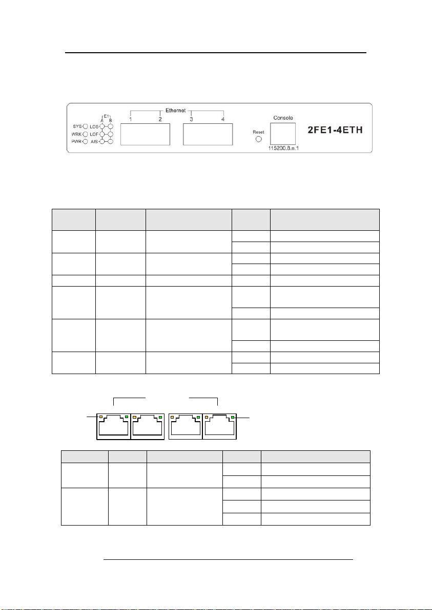
2.1 Introduction to Front Panel of the Device
2.1.1 Device Front Panel
Figure1.1 of Front Panel
2.1.2 Front Panel Indicators Specification
There are 9 indicators on the front panel of the device, and their functions are:
2.1.3 Ethernet
Ethernet
1 2 34
ACT SPD
LED
Name
Colors
Functions
Status
Description
PWR
GREEN
Power Indication
on
Power supply normal
off
Power off
WORK
GREEN
Device Work
Status
on
Device working
off
Not working
SYS
YELLOW
System status
flash
System working
LOSA/B
RED
A/B E1 Loss code
alarm
on
A/B E1 Loss code
alarming
off
Normal
LOF/B
RED
A/B E1 Loss
Frame alarm
on
A/B E1 Loss Frame
alarming
off
Normal
AISA/B
RED
A/B E1 ALL 1
alarm
on
A/B E1 ALL 1 alarming
off
Normal
LED Name
Colors
Functions
Status
Description
SPD1~4
GREEN
Ethernet Speed
Rate
on
100M
off
10M
ACT1~4
YELLOW
Ethernet
Connection
Status
flash
Data transmitting
on
Connected
off
Dis-connected
Manual of 2FE1-4ETH Protocol Converters Equipment
5
2.1.4Reset
The system is in normal operation, if continuously press the Reset button
more than 3 seconds, the system will restore factory default configuration and
reboot.
2.1.5Console
The device provides a series of Config commands and command line
interfaces for configuring and managing the device. Local Config
via the Console port.
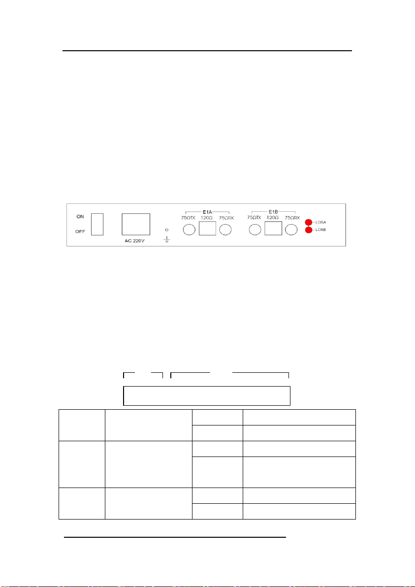
2.2 Introduction to the rear panel of the equipment
2.2.1 Device Rear Panel
Figure 1.2 of Rear Panel
2.2.2 Rear Panel Specification
Two channels of E1 interface with Q9 (75ohm) or RJ45 (120 ohm)
connectors. 220VAC/48VDC Power Interface with a switch. The second
channel of E1 will be disabled when the device under
HDLC/PPP-BCP/GFP-F single E1 mode.
2.3 DIP Switch
SW1 SW2
1 8 1 16
SW1[1-2]
E1 E1 Impedance
ALL ON
75 ohm
ALL OFF
120 ohm
SW1[3-6]
E1 75 ohm
unbalanced
selection
ALL ON
unbalance
ALL OFF
balance
SW1[7]
E1 75 Ohm
unbalanced
ON
E1 shield grounded
OFF
E1 grounded shielded by

Manual of 2FE1-4ETH Protocol Converters Equipment
6
shielded cable
grounding
connection
connected with discharge
tube
SW2
undefined
undefined

Manual of 2FE1-4ETH Protocol Converters Equipment
7
Chapter Three Technical Specifications
3.1 Operating Environment
The device has a wide range of operating temperature and is able
to work normally and stably in highly adverse environment.
Working Temperature 0℃ ~ +50℃
Storage Temperature -40℃ ~ +70℃
Relative Humidity 10 %~95 %
Atmospheric Pressure 70~106 kpa
The environment should be free from corrosive and solvent gases,
dust, and magnetic interference.
3.2 Power Supply Section
Input Voltage:AC 220V/DC 48V
Voltage Fluctuation:100VAC~240VAC/36VDC~72VDC
Power Consumption:<5 W
3.3 Mechanical Specifications
Appearance dimension: 210mm*143mm*41mm
3.4 E1 Interface
Interface Impedance:75Ω,120Ω
Connector Type: Q9(75Ω),RJ45(120Ω)
3.5 Ethernet Interface
Speed rate: 10M/100M Auto-negotiation、10M half-Duplex、10M Full
Duplex、100M Half-Duplex, 100M Full Duplex Optional.
Support VLAN and QinQ function
Manual of 2FE1-4ETH Protocol Converters Equipment
8
Chapter Four Web setting
4.1 WEB Management Requirements
PC Operating system: Win 2000/Win XP/Win7/Linux
Network Connection:Ethernet/FastEthernet
WEB Browser : IE6 or later version,FireFox,and others.
The PC must be in the same subnet with 2FE1-4ETH.
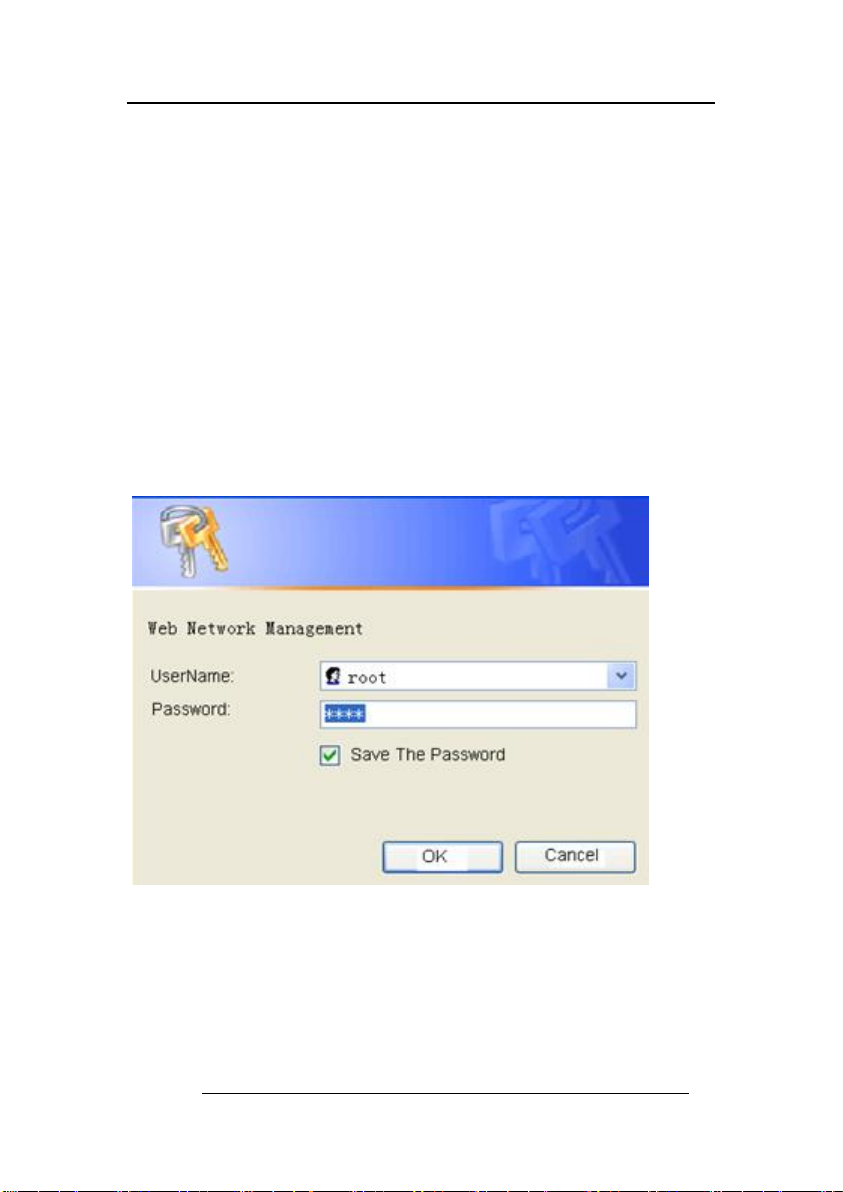
4.2 WEB Login
We use Internet Explorer as the example.Run the browser
program, input the IP address of 2FE1-4ETH in the address bar
with the prefix “http://“. The default address is 192.168.0.168.
The fowling picture shows the login dialog box, input the
right user name and password. User and password both are "root".
The password of the default user "root" can be modified
through CLI(Command Line Interface) or WEB.

Manual of 2FE1-4ETH Protocol Converters Equipment
9
4.3 System Config
4.3.1 System Info
Software Version: The device software version.
Firmware Version: The device firmware (FPGA) version.
Running Time: The time since the device last boots.
MAC Address: The device mac address.
System Name: The system name. Each device can be
assigned different name.
Dot1Q Vlan Enable : The global 802.1Q vlan function.
Admin Vlan : The Admin Vlan, valid when dot1q vlan is
enabled.
QinQ Enable : The QinQ Function, valid when dot1q vlan is
enabled.
QinQ Ethernet Type : The QinQ ethernet type, valid when
dot1q vlan & qinq enabled.
Ethernet Isolation : The 4 ethernet ports isolation.
Config File : If ‘Save’ option selected, the current
configuration will be saved to the flash. If ‘Erase’ option
selected the saved config will be erased from the flash.

Manual of 2FE1-4ETH Protocol Converters Equipment
10
System Reboot : Reboot the system Immediately without
save, or after save , or to factory settings(by erasing the
saved configuration).
4.3.2 Network Config
IP Address : The device IP Address. (default is
192.168.0.168)
Net Mask : The device netmask.
Default Gateway : The device gateway
4.3.3 E1 Config
Work Mode : 2FE1-4ETH support 4 work mode : HDLC 1*E1
/ PPP 1*E1/ GFP 1*E1 / GFP 2*E1.
Manual of 2FE1-4ETH Protocol Converters Equipment
11
Clock Source : Local or Line.
Frame Mode : Frame or Unframe. Valid when work mode is
HDLC/PPP
PCM Mode : PCM30 or PCM31. Valid when work mode is
HDLC/PPP and Frame Mode is Frame.
Time Slot : Such as 1,4,5-31. Valid when work mode is
HDLC/PPP and Frame Mode is Frame.
GFP TxScramble : Disable,Header,Payload or Both. Valid
when work mode is GFP.
GFP RxScramble : Disable,Header,Payload or Both. Valid
when work mode is GFP.
GFP LCAS : Enable Or Disable. Valid when work mode is GFP.
PPP Status : PPP Link Status. Valid when work mode is PPP.
Port Mode : Vlan-Access(Untag) or Vlan-Trunk(Tag). Valid
when dot1q vlan enable.
Dot1Q Pvid : Port Vlan ID.Valid when dot1q vlan enable.
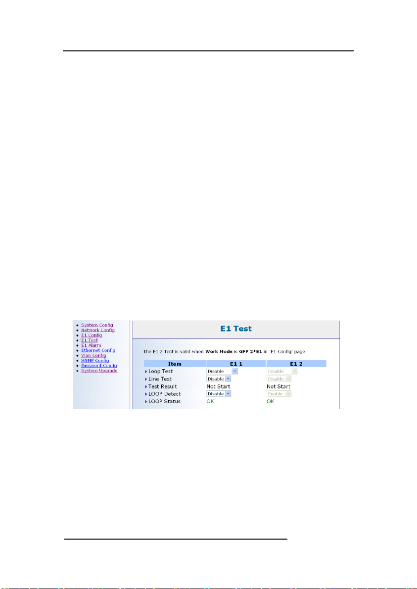
4.3.4 E1 Test
Loop Test : Disable, Local Loop or Line Loop.
Line Test : Disable or Enable
Test Result : Line Test Result.
Loop Detect : Disable or Enable
Loop Status :OK or Alarm.
The E1 2 Test is valid when Work Mode is GFP 2*E1 in 'E1
Config' page
Manual of 2FE1-4ETH Protocol Converters Equipment
12
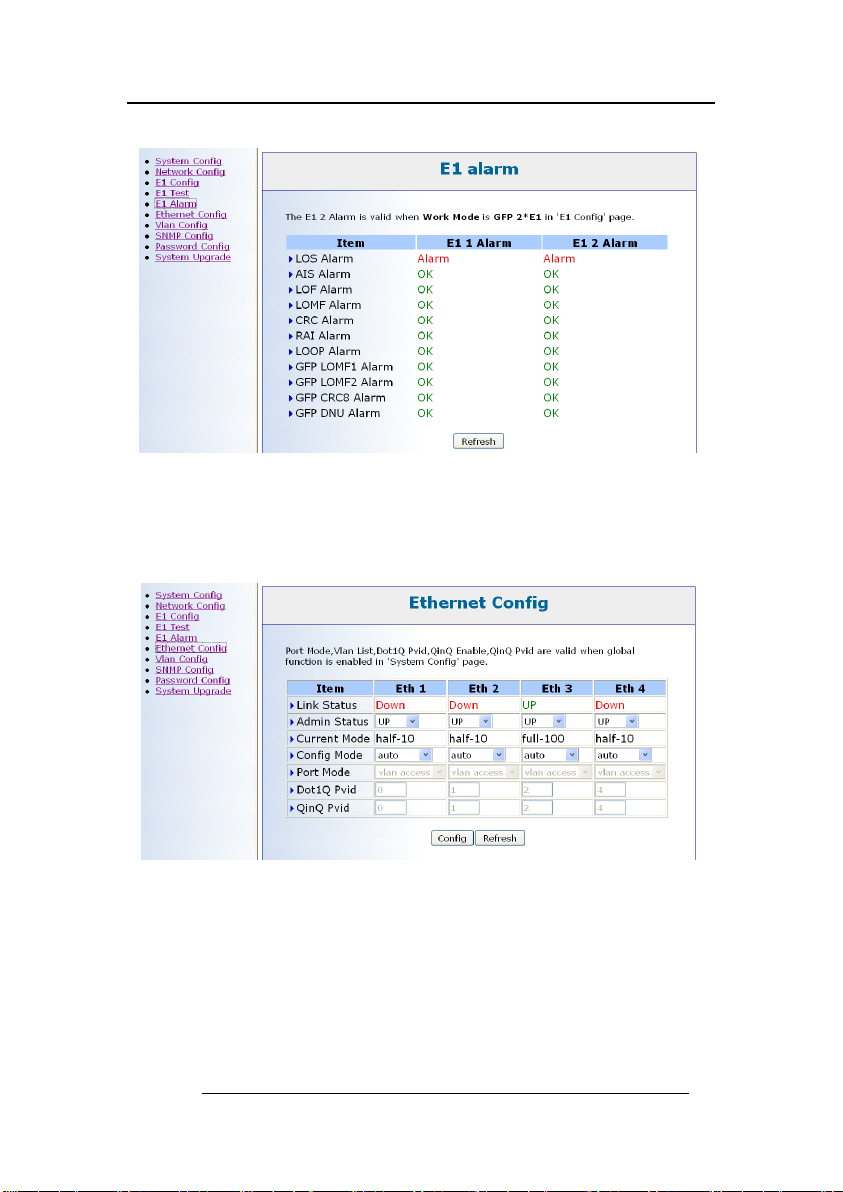
4.3.5 E1 Alarm
This Page Display The E1 Alarms
The E1 2 Alarm is valid when Work Mode is GFP 2*E1 in
'E1 Config' page
4.3.6 Ethernet Config
Link Status : UP or Down.
Admin Status : UP or Down
Current Mode : half-10/full-10/half-100/full-100.
Config Mode : auto/half-10/full-10/half-100/full-100
Loop Status :OK or Alarm.
Port Mode : Vlan-Access(Untag) or Vlan-Trunk(Tag). Valid
Manual of 2FE1-4ETH Protocol Converters Equipment
13
when dot1q vlan enable.
Dot1Q Pvid : Port Vlan ID.Valid when dot1q vlan enable.
QinQ Pvid : QinQ Pvid.Valid when dot1q vlan & qinq enable.
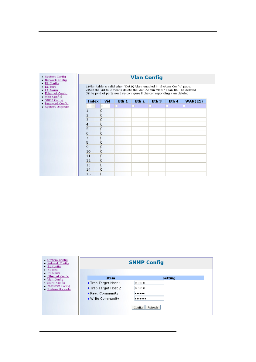
4.3.7 Vlan Config
2FE1-4ETH supports 16 vlan tables.
1)Vlan table is valid when 'Dot1Q Vlan' enabled in 'System
Config' page.
2)Set the vid to 0 means delete the vlan.Admin Vlan can
NOT be deleted
3)The pvid of ports need re-configure if the corresponding
vlan deleted.
4.3.8 SNMP Config

Manual of 2FE1-4ETH Protocol Converters Equipment
14
2FE1-4ETH supports 2 Trap Target Hosts and 2 Communities.
4.3.9 Password Config
This page allows you to change the CLI and WEB password for
the user ‘root’.After you change the password,you need to
re-login with the new password.
4.4.0 System Upgrade
You can upgrade Software(APP) or Firmware(FPGA) via this
page.
The software file name must be *.bin,and the firmware file
name must *.rbf.
Please follow the Step 1 to Step 3 to upgrade,it takes about 10
seconds to upgrade.

Manual of 2FE1-4ETH Protocol Converters Equipment
15
Chapter Five Accessories
5.1 Method of making lines
5.1.1 How to make E1 connecting cable
75ΩLine Making Method: 120ΩLine Making Method:
Connection between core and The pins are arranged as follows:
core and between skin and skin;
No connection between skin and core
芯
皮
1,2,3,4,5,6,7,8
5.1.2Making of Ethernet Interface Connecting Cable
Ethernet interface Connecting Cable adopts twisted pair line with its
specific making methods divided into two international standards, which are
EIA/TIA568A and EIA/TIA568B. Position the tail of crystal head downward
(i.e. the flat side upward), determine the lines with figures as 1 2 3 4 5 6 7 8
from left to right, and the distributions of each line are as follows:
(EIA/TIA568A standard)
(EIA/TIA568B standard)
Pin
No.
Connection signal
Sequence of
twisted pair line
Pin
No.
Connection
signal
Sequence of
twisted pair
lines
1
TX+(transmission)
White and green
1
1
TX+(transmi
ssion)
White and
orange
2
TX-(transmission)
Green
2
TX-(transmis
sion)
orange
3
RX+(receive)
White and
orange
3
RX+(receive
)
White and
green
4
Not to be used
Blue
4
Not to be
used
Blue
5
Not to be used
White and blue
5
Not to be
used
White and
blue
1(+), 2(-) pins are output pins
4(+), 5(-) pins are input pins
Core
Skin

Manual of 2FE1-4ETH Protocol Converters Equipment
16
6
RX-(receive)
Orange
6
RX-(receive)
Green
7
Not to be used
White and
brown
7
Not to be
used
White and
brown
8
Not to be used
Brown
8
Not to be
used
Brown
RJ-45 twisted pair line is specified as follows:
1)1, 2 used to send; 3, 6 used to receive; 4, 5,7, 8 are bi-directional lines.
2)1, 2 must be pair twisted; 3, 6 pair twisted; 4, 5 pair twisted; 7, 8 pair
twisted.
Making of straight-through line: both heads are connected as per T568B
line sequence standard. Making method of crossover line: one head is connected
as per T568A line sequence while the other head is connected as per T568B line
sequence. The follows are specific connection conditions:
1) The device is connected with PC and router: straight-through line shall
be adopted with the same connecting method on both ends of network
line.
2) The device is concatenated with switch (or HUB): crossover line shall
be adopted with different connecting method on both ends of network line.
5.2 Warranty Card
Our company is committed to provide users with the following terms:
1. Warranty service
1) Within the charge free warranty term (within 12 months since the
purchase of the product), damaged parts can be exchanged free of
charge and maintenance charges will be free in the conditions that
the device is considered to be malfunctioned in normal service by
our company.
2) Within the charged warranty term (more than 12 months and within
36 months since the purchase of the product), damaged parts will be
charged for corresponding cost with free maintenance service in the
conditions that the device is considered to be malfunctioned in
normal service by our company.
2. Users can not enjoy warranty service with the following cases and
corresponding cost of damaged parts replacing and maintenance service will be
charged
(1)Exceed 36 months since the purchase of the product
(2)Can’t provide certificate of purchasing date, and serial No. of

Manual of 2FE1-4ETH Protocol Converters Equipment
17
product shows that ex-works term has exceeded 36 months;
(3)Include but not limit to the abnormal service conditions such as
violent knocking, extrusion, drop, liquid immersion that cause
damages;
(4)Fragile label on the device is damaged;
(5)User disassembles this product himself
(6)Force majeure that leads to product damage, such as earthquake,
flooding and lightening stroke;
3. The newly installed parts after maintenance will be repaired free of charge
within 12 months since the installation date.
4. When malfunction occurs, users can choose to send it to our company to
receive maintenance service or to post it to maintenance points of our
company all over the country to be repaired.
5. Our company does not undertake any responsibilities for losses caused by
abnormal operation; for losses really caused by product itself, including
but not limited to all direct or indirect losses due to data loss, our company
will only undertake responsibilities within the selling price of products.
Repair and Maintenance Record
Product Name: 2FE1-4ETH
Device No.:
Maintenance date
No. of Service Bill
1
2
3
4
5

Manual of 2FE1-4ETH Protocol Converters Equipment
18
修改记录:
2012-09-10 Liucf
修改机械尺寸
Table of contents
Popular Media Converter manuals by other brands


StarTech.com
StarTech.com IC232485S instruction manual

IMC Networks
IMC Networks PSE-McBasic Series features and benefits

Advantech
Advantech EKI-2741F user manual

LYNXTechnik
LYNXTechnik yellobrik CQS 1441 quick reference

Matrix Audio
Matrix Audio MUSIC STREAMER COMBO user manual

Trycom Technology
Trycom Technology TRP-C34H user manual