Sendix PROFI BUS Singleturn 5858 Series User manual

T
Te
ec
ch
hn
ni
ic
ca
al
l
M
Ma
an
nu
ua
al
l
AbsoluteSingle/Multiturn
Encoders
SingleturnSeries5858,5878
MultiturnSeries5868,5888
P
Pr
ro
of
fi
ib
bu
us
s
D
DP
P‐
‐D
DI
IN
N
1
19
92
24
45
5‐
‐3
3

Technical Manual
Absolute Single/Multiturn Encoders Profibus
R.000.000 1-2 of 22
CopyrightProtection
Liabilitytomodificationwithoutnotice
As a result of ongoing efforts to improve our products, we reserve the right to make changes at any time to
technicalinformationcontainedinthedocumenttohand.
WarrantyDisclaimer
Their is noprovidenoguarantee,neithertacitnorexpress,inrespectofthewholemanual(whetherthisappliesto
theoriginalGermantextortotheEnglishtranslation)andassumesnoliabilityforanydamage,neitherdirectnor
indirect,howevercaused.
Documentinformation
Revised 09‐2011

Technical Manual
Absolute Single/Multiturn Encoders Profibus
R.000.000 1-3 of 22
TableofContents
1GENERAL.........................................................................................................1‐4
PROFIBUS‐DPBASICS.............................................................................................................................................................................1‐4
THEPROFILEREQUIRED..............................................................................................................................................................................1‐4
CHARACTERISTICS.....................................................................................................................................................................................1‐4
PROTECTIVEFUNCTIONS.............................................................................................................................................................................1‐4
2START‐UP........................................................................................................2‐5
3GENERALWIRINGINSTRUCTIONS....................................................................3‐5
INSTALLATIONINSTRUCTIONSFORRS‐485......................................................................................................................................................3‐5
4CABLESHIELDING............................................................................................4‐6
5CHARACTERISTICSOFTHEMULTITURNENCODERONTHEPROFIBUS..............5‐7
PNO‐IDENT‐NUMBER...............................................................................................................................................................................5‐7
STARTPHASEOFTHEENCODERONTHEPROFIBUS..........................................................................................................................................5‐7
CONFIGURATIONANDPARAMETERISATION.....................................................................................................................................................5‐7
CONFIGURATION......................................................................................................................................................................................5‐7
6DEVICEPROFILE‐PROFILEFORENCODERV1.1...............................................6‐8
CONFIGURATION......................................................................................................................................................................................6‐8
7PROFIBUSENCODERPROFILE3062(VERSION1.1)...........................................7‐9
PRESETSETTING.......................................................................................................................................................................................7‐9
SPEEDVALUES.........................................................................................................................................................................................7‐9
8EXTENDEDDIAGNOSTICS................................................................................8‐10
1.DEVICEPROFILEFORENCODERS..............................................................................................................................................................8‐10
Class1MandatoryforallDPencoders..........................................................................................................................................8‐10
Class2OptionalFunctionality.......................................................................................................................................................8‐10
9INITIALSTART‐UP‐GENERALDEVICESETTINGS..............................................9‐11
Nodenumber(Deviceaddress)......................................................................................................................................................9‐11
10SETSTATIONADDRESS(SSA)*....................................................................10‐11
11EXTERNALPOSITIONRESET..........................................................................11‐11
12PROFIBUSCONNECTIONPG.........................................................................12‐12
SUPPLYVOLTAGE..................................................................................................................................................................................12‐12
13PROFIBUSCONNECTIONM12.......................................................................13‐12
Bustermination..........................................................................................................................................................................13‐13
14INSTALLATIONNOTESWHENUSINGHOUSINGSWITHCABLEGLANDS:........14‐13
15PARAMETERISATION....................................................................................15‐14
16SCALING.......................................................................................................16‐15
17DEFAULTSETTINGSONDELIVERY.................................................................17‐19
ENCODERPROFILE................................................................................................................................................................................17‐19
18GENERALRESETOFTHEDEVICE....................................................................18‐19
19LEDMONITORINGDURINGOPERATION.......................................................19‐20
REDLED=DIAGNOSTICS......................................................................................................................................................................19‐20
YELLOWLED=BUS.............................................................................................................................................................................19‐20
GREENLED=PWRBUSVOLTAGE..........................................................................................................................................................19‐20
LEDCOMBINATIONSDURINGOPERATION...................................................................................................................................................19‐20
GENERALRESET‐SWITCHINGTHEDEVICEONWITHTHESETKEYPRESSED........................................................................................................19‐21
20DEFINITIONS................................................................................................20‐21
21DECIMAL‐HEXADECIMALCONVERSIONTABLE..............................................21‐22

Technical Manual
Absolute Single/Multiturn Encoders Profibus
R.000.000 1-4 of 22
1
1
General
General
PROFIBUS‐DPbasics
ThisdescriptionprovidesinformationconcerningtheimplementationofthePROFIBUS‐DPtransmissionprotocolintheslave
modeinourdevices.Itshouldbenotedthattheextentofthefunctionsdescribedmightbelimitedaccordingtothedeviceor
application.Withprotocolconversionsinparticular,asarulefewerfunctionsareused!
Theprofilerequired
Thelinkbetweenthedecentralizedprocessoperationandthecentralcontrolviathecommunicationsystemtakesplacein
thelowesthierarchylevelonthefiledorprocessbus.Atthislevel,themainrequirementsareasimpleprotocoloperation
andshortdatatransmissiontimesforthecommunication.Thisensuresthefastestsystemreactiontimetothedynamic
statesoftheperipherals.Inadditiontotheclassicdataexchange,theacyclictransmissionofparameter,diagnosticand
configurationdatamustbepossible,withoutradicallyimpedingthereal‐timecapabilityofthebus.Thisistheonlywayto
guaranteetheachievementofgooddiagnosticsandsafeoperation.
Characteristics
ThemaintaskofPROFIBUS‐DPisthecyclictransmissionoftheprocessdatafromthecontrolsystemtotheperipheral
equipmentandviceversa.TheaccessprocedureusestheMaster‐Slaveprinciple.HereinthepollingoperationaMaster
communicateswithitsassignedslavedevicesoneaftertheotheronthebus.Adataexchangeisinitiatedbyarequest
telegramandendedbyanacknowledgementtelegramfromtheSlaveconcerned.So,eachSlaveonlybecomesactiveaftera
callfromtheMaster.Thisavoidsasimultaneousbusaccess.ThehybridaccessprocedureofPROFIBUSallowsacombined
operationofseveralbusmastersandevenamixedoperationofPROFIBUS‐DPandPROFIBUS‐FMSwithinabussection.
Howeverthepre‐requisitionforthisisthecorrectconfigurationofthebussystemandtheunambiguousassignmentofthe
SlavedevicestotheMasters.PROFIBUS‐DPdistinguishestwotypesofMaster.TheClass1Mastercarriesoutthecyclic
transmissionoftheoperatingdataandsuppliestheuserdata.TheClass1MastercanbeaddressedbyaClass2Masterusing
certainfunctions.DirectaccesstotheSlavesisnotpermitted.Thefunctionsarelimitedtosupportservicessuchasreading
thediagnosticinformationoftheslaves.AClass2Masteristhusalsounderstoodasaprogrammingordiagnosticdevice.
Protectivefunctions
PROFIBUS‐DPisequippedwithmanyprotectivefunctions.Theseensuresafefault‐freecommunicationnotonlyintheharsh
environmentofthedecentralisedperipheralequipment,butalsointhecaseofexternalinterferenceorthefailureofoneor
morestations.Wrongparametersettingsarerecognizeddirectly,inthatstationshavingthewrongparametersarenot
integratedintheoperatingdataexchange.
TheMasterrecordsthefailureofanystationandindicatesthistotheuserbymeansofageneraldiagnosticmessage.
AnybreakdowninthetransmissionpathisdetectedbytheSlavebymeansoftimemonitoringandleadstotheoutputsbeing
switchedoff.
EMVdisturbancesarevirtuallyfilteredoutbymeansofthedifferencesignal,thankstotheparticularlynoise‐immuneRS485
transmissionsystem.
Datatransmissionerrorsarerecognizedthankstoframeandcheck‐sumcontrolsandleadtotheretransmissionofthe
telegram.

Technical Manual
Absolute Single/Multiturn Encoders Profibus
R.000.000 3-5 of 22
2
2
Start-up
Start-up
BeforeaPROFIBUS‐DPsystemcanbestartedup,uniquebusaddressesmustbeassignedtoallconnectedstations,including
theMastersystem.Thisistheonlywaytoensureunambiguousaddressingonthebus.Asanoption,thestationaddresses
canalsobeassignedviathebus.
ThephysicalsystemsettingsaremadeusingtheparametersetoftheMaster.InadditiontothebusaddressoftheMaster,
thissetincludes,forexample,thebaudrate,thetime‐outdelaysandthenumberofrepetitionsofthetransmission.Along
withtheMasterparameterset,aSlavedatasetmustbesavedforeachSlavetobeactivated.Adatasetcontainsthe
parameterassignmentandconfigurationdataoftheSlaveandtheaddressindicatorforthelogicalstorageoftheI/Odata.If
theparametersetsarepresent,theneitherattherequestoftheuserorautomaticallytheMastersystembeginstostartthe
Slavesup,oneaftertheother.Thefirstso‐calleddiagnosticcyclesareabletoshow,whichslaveispresentonthebus.Only
thoseSlaves,whichsentacorrectfeedbackduringthediagnosticcycle,willsubsequentlybeparameterizedintheparameter
cycleswiththecorrespondingdatastoredintheMaster.Ifthishasbeencorrectlycarriedout,thenconfigurationcycles
follow,duringwhichacomparisonismadebetweentherequiredconfigurationdatastoredintheMasterandtheactual
configurationdataoftheSlave.Afterthelastdiagnosticcycle,eachSlaveforwhichnoerrorwasdetectedduringthe
comparisonisreadyforoperation.EachoftheseSlavesisthenintegratedautomaticallybytheMasterintheoperatingdata
transfer.
Fordiagnosticpurposes,theMasterprovidesadiagnosticbufferforeachSlave,whichcanbereadbytheuserforother
purposes.Tosimplifythediagnostics,ageneraldiagnosticfieldiskeptsimultaneously,whichshowsbitwisewhetheraSlave
hasdiagnosticdatareadyornot.
3
3
General
wiring
instructions
General wiring instructions
InstallationinstructionsforRS‐485
Alldevicesareconnectedwithinabusstructure(line).Upto32stations(MasterorSlaves)canbelinkedtogetherinone
segment.Thebusisterminatedatthebeginningandattheendofeachsegmentbyanactivebustermination(termination
resistors).Toensuredisturbance‐freeoperationbothbusterminationsmustalwaysremainpowered.Thebusterminationis
providedready‐to‐activateinthedeviceofintheconnector.
Whentherearemorethan32stationsonthebus,repeatersmustbeinsertedtoconnecttheindividualbussegments.
Themaximumlinelengthisdependentonthetransmissionspeed–refertoTable2.
Thelinelengthindicatedcanbeincreasedusingrepeaters.Itisrecommendednottoconnectmorethan3repeatersin
succession.
Baudrate(kBit/s)9.619.2 93.75 187.5 500150012000
Range/Segment1200m 1200m 1200m 1000m 400m200m100m
Table2:RangedependingonthetransmissionspeedforA‐typecable

Technical Manual
Absolute Single/Multiturn Encoders Profibus
R.000.000 4-6 of 22
4
4
Cable
shielding
Cable shielding
EN50170leavesituptotheusertodecide,whethertouseshieldedorunshieldedcable.Unshieldedcableisallowedin
interference‐freeenvironments.However,thefollowingpointsargueforsystematicuseofshieldedcable:
a) Anareafreefrominterferenceexistsatbestinsideshieldedcabinets.Butassoonasthiscontainsotherelectronic
devicessuchasrelaysandcontactors,thenthisisnolongerguaranteed.
b) Theuseofunshieldedcablesrequiresadditionalprotectivemeasuresagainstovervoltageatthebussignalinputs.
Thisiswhywerecommendonprincipletheuseofshieldedcablesforthebuslines.Thisrecommendationextendsalsotothe
possibleuseofpower‐supplycablescomingfromexternalpowersourcestothePROFIBUSdevices,e.g.forrepeaters.
Double‐shieldedcablesareparticularlysuitableforenvironmentswithstrongEMCinterference.Inthiscase,inorderto
ensureoptimalprotection,thewholesurfaceoftheexternalshielding(braidedshield)andtheinnershielding(foilshield)
mustbeconnectedatbothcableendstotheprotectiveearthbymeansofanearthclip.
Shieldingrules
Whenusingashieldedbuscable,itisrecommendedtoconnecttheshieldatbothendstotheprotectiveearthusinglow‐
inductionconnections.Thisensuresthehighestpossibleelectromagneticcompatibility(EMC).Oneexceptionconcerns
separatedpotentials(e.g.inrefineries):generally,intheseplants,earthingispermittedatoneendonly.
Theconnectionbetweenthecableshieldingandtheprotectiveearthisbestdoneusingthemetallicdevicehousingandthe
screwterminaloftheplugconnector.Hereitshouldbenotedthatdischargeviathepindoesnotrepresentanoptimal
solution.ToachievethebestEMC,itisbettertoexposethecableshieldingatasuitablelocationandtoconnectittothe
protectiveearth(e.g.themetalliccabinetframe)usingalow‐inductioncablelinkthatshouldbekeptasshortaspossible.
Thiscanbedoneforexamplewithashieldingclipbeforethebusplug.
Cablespecification:A‐typecableforPROFIBUS–DP
Surgeimpedance:135to165Ohm,forameasurementfrequencyof3to20MHz.
Cablecapacitance:<30pFpermetre
Conductorsection:>0.34mm²,correspondstoAWG22
Cabletype:twistedpair,1x2or2x2or
1x4conductors
Loopresistance:<110Ohmperkm
Signaldamping:max.9dBoverthewholelengthofthecablesection
Shielding:Copperbraidshieldingorbraidshieldingandfoilshielding

Technical Manual
Absolute Single/Multiturn Encoders Profibus
R.000.000 5-7 of 22
5
5
Characteristics
of
the
Multiturn
Encoder
on
the
Profibus
Characteristics of the Multiturn Encoder on the Profibus
PNO‐Ident‐Number
TheSendixAbsoluteSingleturn/MultiturnEncoderhasthePNO‐Ident‐Number5868(Hex).Thisnumberisregisteredatthe
PNO(ProfibusUserOrganization)asanuniqueidentification.TheaccordingGSD‐Filesarenamedasfollows:
•MultiturnSeries5868,5888 KUEB5868.GSD
•SingleturnSeries5858,5878 KUEB5868ST.GSD
StartphaseoftheencoderonthePROFIBUS
Whentheencoderstartsupitisinthe‘Baud‐Search’state.Oncethebaudratehasbeenrecognized,itswitchestothe
WAIT_PRMstateandwaitsfortheparameterdatafromtheDP‐Master.Theparameterisationoccursautomaticallywhenthe
DP‐Masterstartsup.Thefollowingparametersaretransmittedtotheencoder:countdirectionandthemeasuringlengthin
steps(formoredetails,seetheEncoderProfilefromthePNO).Whenthecorrectparameterdatahavebeensuccessfully
transferred,theencoderswitchestotheWAIT_CFGstate.ThePROFIBUSMasterthensendsaconfigurationbyteto
determinethenumberofinputs/outputs.Iftheconfigurationbyteiscorrect,theencoderswitchestothestate
DATA_EXCHANGE.
ConfigurationandParameterisation
Theparameterisation,i.e.thetransferoftheparametersforcountdirection,encoderresolutionetc.,normallyoccurswithin
theconfigurationprogrammeforthePROFIBUSMasterused.Todothis,thetypefileorGSD(devicefile)shouldbecopiedto
therespectivedirectoryfortypeorGSDfiles.WithsomeprogrammessuchasCOMPROFIBUSorSTEP7Manager,anupdate
oftheinternaldevicelist(hardwarecatalogue)mustbecarriedoutwithinthesoftware.Formoreinformationabout
integratingfielddevices,pleaserefertothedocumentationforthesoftwareyouareusing.
ThetwostepsdescribedbelowarenormallynecessaryforintegratingandparameterisingtheencoderinaMastersystem.
Configuration
Forconfigurationpurposes,i.e.toinputthelengthandtypeoftheI/OonthePROFIBUS,theconfigurationprogramme
normallyprovidesaninputmask(screen),inwhich–independentlyofthedesiredconfiguration–theidentifierhasnormally
alreadybeensetasadefault,sothatonlytheI/Oaddressesremaintobeentered.Dependingontherequiredconfiguration
thatisdesired,theencoderallocatesavaryingnumberofinputandoutputwordsonthePROFIBUS.
Thefollowingparametersdescribedarealsodependentontherequiredconfiguration.TheGSDdevicefile(e.g.
KUEB5868.GSD)containsfiverequiredconfigurationsforPNOClass1and2,eachwith16‐and32Bitresolution.

Technical Manual
Absolute Single/Multiturn Encoders Profibus
R.000.000 6-8 of 22
6
6
Device
Profile
-
Profile
for
Encoder
V1.1
Device Profile - Profile for Encoder V1.1
Thisprofiledescribesamanufacturer‐independentandmandatorydeterminationoftheinterfaceforencoders.Itisdefined
intheprotocol,whichProfibusfunctionsareusedaswellashowtheyaretobeused.Thisstandardpermitsanopen
manufacturer‐independentbussystem.
Thedeviceprofileisdividedintotwoobjectclasses:
•ClassC1describesallthebasicfunctions,whichthe
encodershouldcontain.
•ClassC2containsanumberofextendedfunctions,which
musteitherbesupportedbyencodersofthisclass
(Mandatory)orwhichareoptional.ClassC2devicesthus
containalltheC1andC2mandatoryfunctions,aswellas
additionalmanufacturer‐dependentoptionalfunctions.An
addressareaisalsodefinedintheprofile,whichcanbe
reservedforamanufacturer’sownproprietaryspecial
functions.
Configuration
Theconfigurationprogrammenormallyprovidesaninputmask(screen)forparameterisationpurposes,i.e.forenteringthe
dataforresolution,countdirectionetc.Theindividualmodulesarelistedbelow:
7configurationsareavailablefortheregularoperationoftheencoder:
-32BitInput/Output,consistent
-32BitInput,consistent
-16BitInput/Output,consistent
-16BitInput,consistent
-MUR=13BitandTMR=25Bit(32BitInput/Output,consistent)
‐allcancombinedwithSpeed(RPM)16BitconsistentorSpeed(Units/s)32Bitconsistent

Technical Manual
Absolute Single/Multiturn Encoders Profibus
R.000.000 7-9 of 22
7
7
Profibus
Encoder
Profile
3062
(Version
1.1).
Profibus Encoder Profile 3062 (Version 1.1).
Class232‐Bitresolution,Input/Outputconsistent:
Theencoderuses2inputwordsand2outputwords,whichareeachconsistentlytransmittedoverthebus.
Class232‐Bitresolution,Inputconsistent:
Theencoderuses2inputwords,whichareeachconsistentlytransmittedoverthebus.
Class116‐Bitresolution,Input/Outputconsistent:
Theencoderuses1inputwordand1outputword,whichareeachconsistentlytransmittedoverthebus.
Class116‐Bitresolution,Inputconsistent:
Theencoderuses1inputword,whichisconsistentlytransmittedoverthebus.
Combinationwith:
Class232‐Bitresolution,InputconsistentSpeedin(units/s)or
Class216‐Bitresolution,InputconsistentSpeedin(rpm)
Theencoderusesmax.2inputwords,whichareeachconsistentlytransmittedoverthebus.
DefaultsettingScalingon,25Bittotalresolution
Class232‐BitresolutionMUR=13Bit,TMR=25Bit:
Presetsetting
Inthemode‘Class2’theencodercanbeadjustedoverthePROFIBUStoanypositionvalueinthevaluerangeof27Bitor15
Bit.
Thisoccursbysettingthemostsignificantbit(MSB)oftheoutputdata(2^31for
configurationClass2‐32Bitor2^15forconfigurationClass2‐16Bit).
ThePresetValuethatistransmittedinthedatabytes0‐3isacceptedasthepositionvaluewiththerisingedgeofBit32
(=Bit7ofdatabyte3).Theencoderthencontinuescountingfromthisposition.Anewadjustmentisthenonlypossibleafter
thecontrolbithasbeenreset.Thereisnoacknowledgmentofthisactionviatheinputs.
Speedvalues
AllmodulescanbecombinedwiththeconfigurationofanadditionalSpeedvalue.Theinputwordsareincreasedtoa
maximumlengthof8Bytes(64Bit)dependingontheconfigurationofthespeedvalue.TheSpeedvalueissignedand
dependsonthecountdirection.
PositivevaluesinCW,negativeinCCWdirection.
Formatisin“BigEndian”:
Inputword Inputword
Byte0Byte1Byte2Byte3FormatMax.
00RPM0
1770 RPM6000
E890 RPM ‐6000
0063FF9C Units/s6553500
FF9C0064 Units/s‐6553500
Speedlimits:
SingleturnEncoder: 600rpmhigherspeedshowsffffhasvalue
Multiturnencoder: 12000rpmhigherspeedshowsffffhasvalue

Technical Manual
Absolute Single/Multiturn Encoders Profibus
R.000.000 8-10 of 22
8
8
Extended
Diagnostics
Extended Diagnostics
1. Deviceprofileforencoders
C
Cl
la
as
ss
s
1
1
M
Ma
an
nd
da
at
to
or
ry
y
f
fo
or
r
a
al
ll
l
D
DP
P
e
en
nc
co
od
de
er
rs
s
FunctionOctetN°.DataTypeName
Data_Exchange1‐4Unsigned32PositionValue(input)
Data_Exchange1‐4Unsigned32PresetValue(output)
Data_Exchange1‐4Unsigned32SpeedValue(input)(units/s)
Data_Exchange1‐4Unsigned16SpeedValue(input)(rpm)
RD_inp1‐4Unsigned32PositionValue
RD_inp1‐4Unsigned32SpeedValue
Slave_Diag7OctetStringExternalDiagnosticHeader
Slave_Diag8OctetStringAlarms
Slave_Diag9OctetStringOperatingStatus
Slave_Diag10OctetStringEncoderType
Slave_Diag11‐14Unsigned32SingleturnResolution
Slave_Diag15,16Unsigned16NumberofRevolution
Set_prm9OctetStringOperatingParameters
C
Cl
la
as
ss
s
2
2
O
Op
pt
ti
io
on
na
al
l
F
Fu
un
nc
ct
ti
io
on
na
al
li
it
ty
y
FunctionOctetN°.DataTypeName
Slave_Diag17OctetStringAdditionalAlarms
Slave_Diag18,19OctetStringSupportedAlarms
Slave_Diag20,21OctetStringWarnings
Slave_Diag22,23OctetStringSupportedWarnings
Slave_Diag24,25OctetStringProfileVersion
Slave_Diag26,27OctetStringSoftwareVersion
Slave_Diag28‐31Unsigned32OperatingTime
Slave_Diag32‐35Signed32OffsetValue
Slave_Diag36‐39Signed32ManufacturerOffsetValue
Slave_Diag40‐43Unsigned32MeasuringUnitsperRevolution
Slave_Diag44‐47Unsigned32Totalmeasuringrangeinmeasuringunits
Slave_Diag48‐57ASCIIStringSerialNumber
Set_prm10‐13Unsigned32MeasuringUnitsperrevolution
Set_prm 14‐17 Unsigned32Totalmeasuringrangeinmeasuringunits

Technical Manual
Absolute Single/Multiturn Encoders Profibus
R.000.000 11-11 of 22
9
9
I
In
ni
it
ti
ia
al
l
S
St
ta
ar
rt
t-
-u
up
p
-
-
G
Ge
en
ne
er
ra
al
l
D
De
ev
vi
ic
ce
e
S
Se
et
tt
ti
in
ng
gs
s
N
No
od
de
e
n
nu
um
mb
be
er
r
(
(D
De
ev
vi
ic
ce
e
a
ad
dd
dr
re
es
ss
s)
)
Settingthenodenumberfortheaddress,usingbothrotaryswitchesandadjustthenumbertotheaccording
address.R1fortheloworderaddresses,R2forthehighordervalue.
View:intotheopenedbuscover
RotaryswitchforloworderR1
Rangeofvalues1..F*
RotaryswitchforhighorderaddressR2
Rangeofvalues1..7*
²
Example:
R1settoF,R2setto3
3Fhcorrespondsto63decimal
1
10
Set
Station
address
(SSA)
*
0 Set Station address (SSA) *
*AdjustbothrotaryswitchestopositionFforSoftware“setstationaddress”supportwithaClass2Master.
TheSoftware“setstationaddress”supportcanonlybecarriedoutwithaClass2Master.
DefaultsettingsafteraPower‐onistheaddress125(0x7D)forSSA_Support.
Onlyvalidaddresseswillbestoredinanon‐volatilememoryandareactivebynow.
TheNodenumber0isreservedandmustnotbeusedbyanynode.
Theresultingnodenumberslieintherange1...7Dhhexadecimal(1...125decimal).
11
1
External
Position
Reset
1 External Position Reset
Thedevicecanbesettoaresetpositionbymeansofthe
built‐inSETkey.Theresultingpositionis0.
Theresultingoffsetbetweenthephysicalzeroposition
ofthediscandtheelectroniczeropositioncanbe
interrogatedviatheextendeddiagnosticsheader.
Position:0
Asperillustration

Technical Manual
Absolute Single/Multiturn Encoders Profibus
R.000.000 13-12 of 22
1
12
2
P
Pr
ro
of
fi
ib
bu
us
s
c
co
on
nn
ne
ec
ct
ti
io
on
n
P
PG
G
BusconnectionwithseparatepowersupplyandPGcableglandconnection
Undobothscrewsonthebuscoverandremovethebuscoverfromtheencoder.
Feedtheincomingbuscablethroughtheleftcableglandandconnectittotheleftterminal(B)andterminal(A).
Placethecableshieldontothecablegland.Iffurtherdevicesfollowinthebussegment:
Runcontinuingcablethroughtherightcableglandandconnecttoterminal(B)andterminal(A).
Supplyvoltage
Runthesupplyvoltagefortheencoderthroughthecentralcableglandandconnectittotheterminalsontheleft
(+V)and(0V).Placethecableshieldontothecablegland.
(seewiringdiagram)
View:intotheopenedbuscover
Descriptionfromlefttoright
Abbreviation DescriptionDirection
BProfibusOut
AProfibusOut
0V0VoltSupplyOut
+V+UBSupplyOut
0V0VoltSupplyIn
+V+UBSupplyIn
BProfibus In
AProfibusIN
1
13
3
P
Pr
ro
of
fi
ib
bu
us
s
C
Co
on
nn
ne
ec
ct
ti
io
on
n
M
M1
12
2
Technical Manual
Absolute Single/Multiturn Encoders Profibus
R.000.000 14-13 of 22
B
Bu
us
s
t
te
er
rm
mi
in
na
at
ti
io
on
n
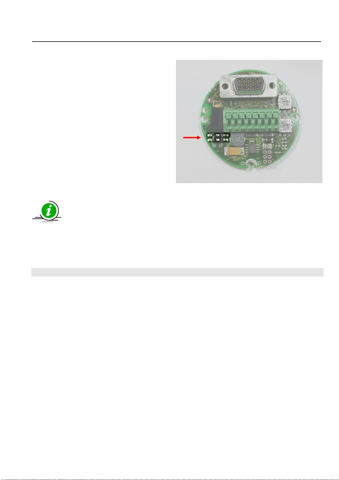
Thebusterminationissetviahardwareusingboth
DIPswitchesonthebuscoverontherearofthe
encoder.
Whentheswitchissetto‘ON‐>theterminationis
active
Ifthedevicerepresentsthefinalstationonthebus,
thenthelooped‐throughProfibusmustbeactively
terminatedatbothendswithabustermination
resistorbetweenAandB.
Atclosedhousingsitisnecessarytoorderwithterminationadjustedtherightway,otherwiseit
ismandatorytoadaptanexternalresistor.
14
4
Installation
notes
when
using
housings
with
cable
glands:
1 Installation notes when using housings with cable glands:
Asbusorconnectioncable,useonlyapprovedProfibuscablewithsuitableshielding.
•Placethecableshieldonthecablegland

Technical Manual
Absolute Single/Multiturn Encoders Profibus
R.000.000 15-14 of 22
1
15
5
P
Pa
ar
ra
am
me
et
te
er
ri
is
sa
at
ti
io
on
n
Inordertocarryoutageneralparameterisationofthedevice,itisnecessaryfirsttoselectamodulefromtheGSDfile
(KUEB5868.GSD).
Example:
Withtheparametertelegram(exceptforthe25‐Bitconfiguration)thefollowingcanbedefined:
-CodeSequence(Octet9,Bit0)
o0=clockwise
o1=counterclockwise
-Class2functionality(Octet9,Bit1)
o0=no
o1=yes
-Scalingenabled(Octet9,Bit3)
o0=no
o1=yes
-Scalingtype(Octet9,Bit7)
o0=Standard(MUR+TMR)
o1=Alternative(NDR+TMR)
-ScalingparameterMURorNDR(Octets10‐13)
oMUR=MeasuringUnitsperRevolution
oNDR=NumberofDistinguishedRevolutions
-ScalingparameterTMR(Octets14‐17)
oTMR=TotalMeasuringRange
Technical Manual
Absolute Single/Multiturn Encoders Profibus
R.000.000 16-15 of 22
1
16
Scaling
6 Scaling
WithStandardScaling,scalingwillbedoneasfollows:
oWithMURandTMR
oOnerevolutionisequivalentexactlytoMUR=TMRvalues
Positionscaled=((Positionunscaled/Singleturn‐resolution)*MUR)%TMR
WithAlternativeScaling,scalingwillbedoneasfollows:
oWithNDRandTMR
oNDRrevolutionsareequivalentexactlytotheTMRvalues
Positionscaled=((Positionunscaled/(NDR*Singleturn‐resolution))*TMR)%TMR
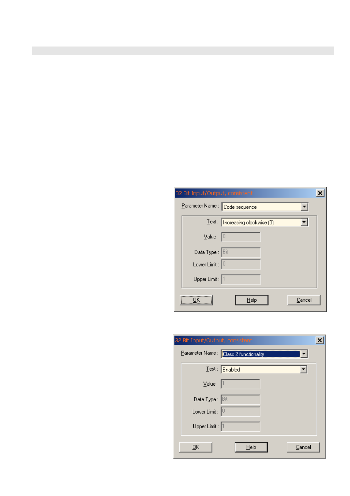
1. CodesequenceCW
Possiblesettings:
Increasingclockwise(0)(CW)
Increasingcounter‐clockwise(1)(CCW)
2. Class2functionalityon
Class2mustbeturnedonwhenscalingisactive.
Technical Manual
Absolute Single/Multiturn Encoders Profibus
R.000.000 16-16 of 22
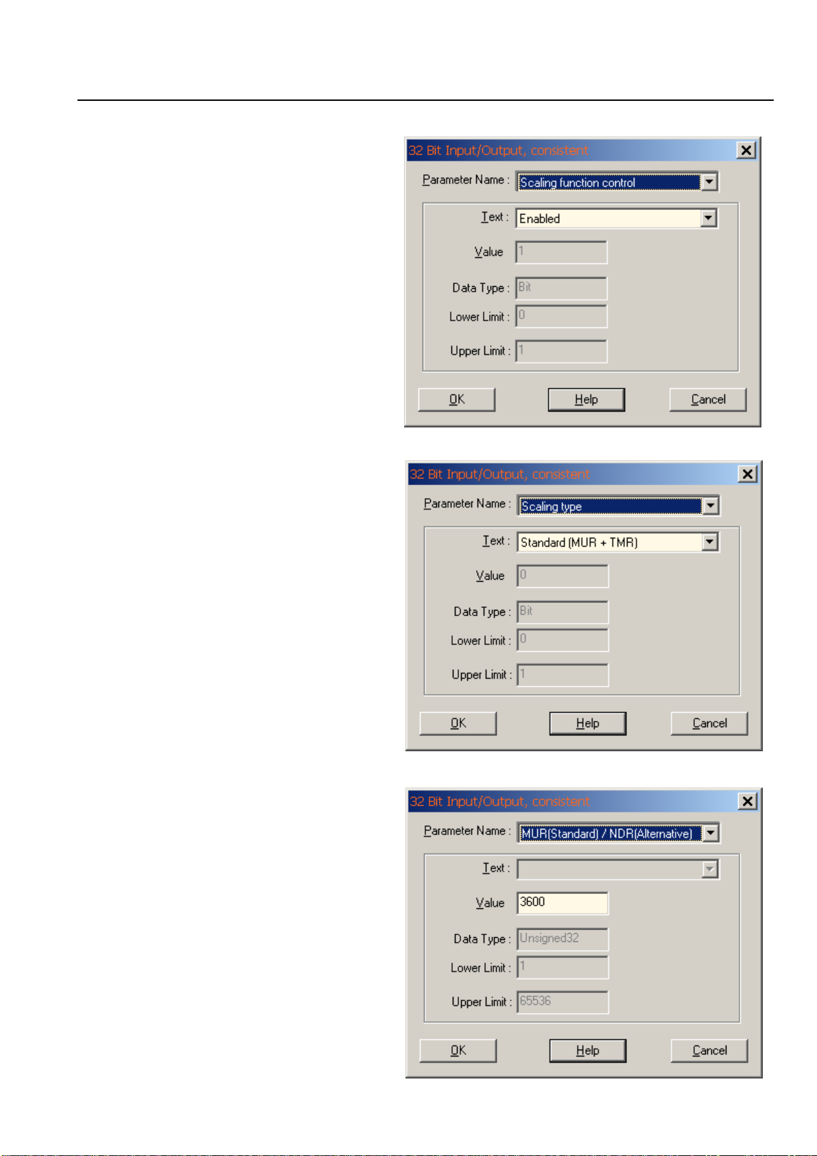
3. Scalingfunctioncontrolon
Whenscalingisturnedon–Position
dependsonthevaluesMURandTMR.
4. Scalingtype
MUR+TMR
Scalingtype(MUR+TMR)
5. ValueforResolutionper
RevolutionMUR
Example:3600Stepsperrevolution
Technical Manual
Absolute Single/Multiturn Encoders Profibus
R.000.000 16-17 of 22
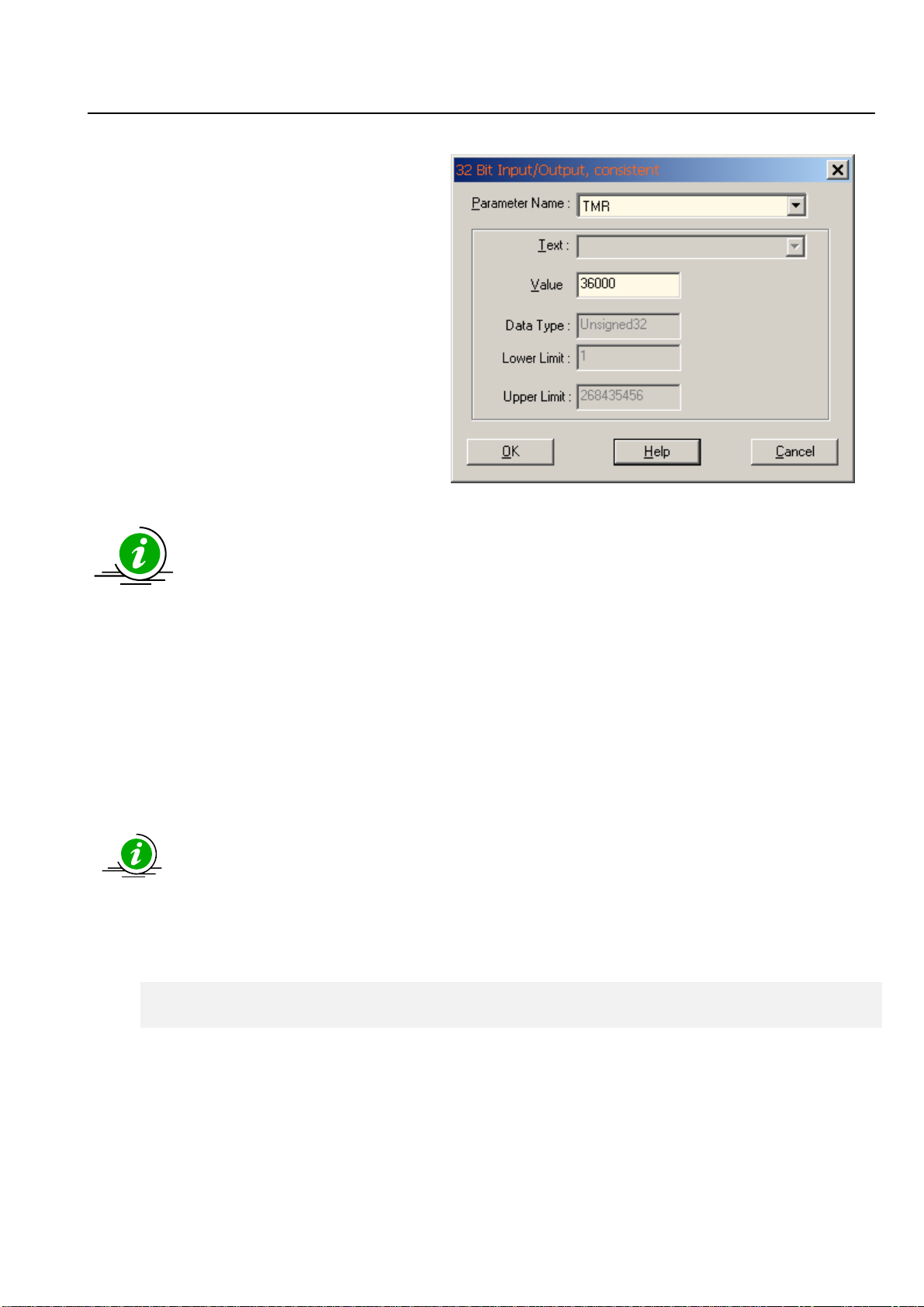
6. ValueforTotalResolution
Example:Valuefortotalresolution36000
Positionrange:0…36000
Revolutions10
WithStandardScaling,scalingwillbedoneasfollows:
oWithMURandTMR
oOnerevolutionisequivalentexactlytoMUR=TMRvalues
Positionscaled=((Positionunscaled/Singleturn‐resolution)*MUR)%TMR
Ifthescalingvalues(TMR/MUR)cannotbedividedwithoutaresttherewillbeanerroratthelimitsofthe
positionvalues(value<0and<maximumposition).ThiscanbeavoidwithamultiplevalueofMURtoTMR.
*Limitations
ThecalculatedfactorGP_U/TMRshouldalwaysbeanintegernumber
k=GP_U/TMRk=Integernumber
Example
InputObject6001hMUR=65000
InputObject6002hTMR=65.000.000
Calculatednumberofrevolutions=1000(MT)
k=GP_U/TMRk=Integernumber
Fault k=228/65.000.000=4,1297
Technical Manual
Absolute Single/Multiturn Encoders Profibus
R.000.000 16-18 of 22
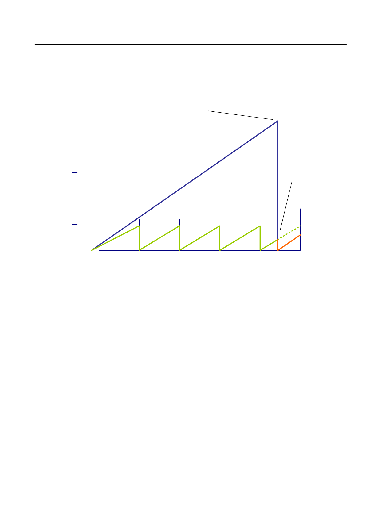
Positiondiagram
Total Measuring Range (TMR)
0 Number of Revolutions
Max
4000 0 1 2
2000 U
Error behavior
MT resets the
position value
4000 U
Max.physical Resolution 2^28 Bit
Singleturn Resolution (MUR) * 4096
= TMR
Attheendoftthephysicalresolution(GP_U)itcomestoafault,becausetheinputofkisno
integernumber.TheEncoderresetsthepositionattheendoftheMultiturntoZero.Thesame
faultoccursimmediatelywhenafterapresettozerothemaximumvalueoftheMultiturn(4095)
willbeadjusted.

Technical Manual
Absolute Single/Multiturn Encoders Profibus
R.000.000 18-19 of 22
1
17
7
D
De
ef
fa
au
ul
lt
t
s
se
et
tt
ti
in
ng
gs
s
o
on
n
d
de
el
li
iv
ve
er
ry
y
Ondeliverythefollowingparametershavebeenfactoryset.
DescriptionSettingSwitch
BaudrateautomaticNotavailable
Nodeaddress63Switchsetting3Fh(63)*
*Atclosedhousingstheswitchissettothepreordednode
addressorto0xFFfor“setstationaddress”withsoftware
TerminationOFFSwitchsettingof
f
Index(hex)NameStandardvalue
EncoderProfile
Set_prm9OperatingParameter Bit3Scalingon
Class2on/CW
Set_prm10‐13MeasuringUnitsperRevolution 8192(13Bit)
Set_prm14‐17TotalMeasuringRange 33554432(25Bit)
TheoriginalStandardValues(Defaultvaluesondelivery)canbereloadedbypressingthebutton
ontherearwhenswitchingon(Restoreparameters).
Iferrorshaveoccurredduringprogrammingoftheobjectsandiftheseparametershavebeen
savedintheEEPROM,itwillnotbepossibletoaddresstheencodernexttimeitisswitchedon;
thiserrorcanbeclearedonlybymeansofageneralResetoftheencoder.
18
8
General
Reset
of
the
device
1 General Reset of the device
Pleasenotethatallprogrammedparameterswillbelost.
•Switchtheencoderoff.
•Turntheencoderbackon,keepingtheSET‐Key*pressedforapprox.3sec.
untiltheDIAGLEDflashes
•Switchthedeviceoffagain
Whentheencoderisrebootedallvalueswillberesettotheirdefault
settings.(SSA‐addressis125)
*onlyfordeviceswithanexternalSET‐Key;inothercasesthedeviceshouldbe
returnedtothefactory.
Technical Manual
Absolute Single/Multiturn Encoders Profibus
R.000.000 19-20 of 22
1
19
9
L
LE
ED
D
M
Mo
on
ni
it
to
or
ri
in
ng
g
d
du
ur
ri
in
ng
g
o
op
pe
er
ra
at
ti
io
on
n
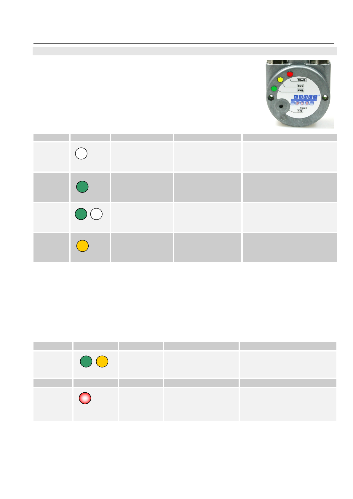
redLED=DIAGnostics
yellowLED=BUS
greenLED=PWRBusvoltage
AnnunciatorLEDDescriptionCauseoferror Addendum
PWR
OFF
Nobusvoltage
present
Nopowertodevice
Powersupplyunit
defective
Checkpowersupply³
PWR
ON
Busvoltagepresent.
Devicereadyfor
operation
Deviceisinconfiguration
mode
BUS
OFF
Deviceiswaitingfor
configurationor
parameterisation
GSDmodulemustbe
loadedandsenttothe
encoder
ObservecombinationwithDIAG
LED
BUS
ON
ConnectiontoMaster
established
DATA_ExchangeMode
Exchangeofprocessdata
TheindividualLEDannunciatorscanofcoursealsooccurincombinations.
²MastercanbeeitheraPLCorasecondcommunicationpartner
³Operatingvoltage
LEDcombinationsduringoperation
AnnunciatorLEDDescriptionCauseoferrorAddendum
PWR+BUS
ON
Data_Exchange
Mode
Devicewillexchangepositiondata
Diag
flashing
RedLEDflashingOver‐temperature
Sensormonitoring
Singlebitfunctionerror
Sensorcurrentmonitoring
ConnectiontoMasterinterrupted+
additionalcausesoferror(Diagnostic
headerisrequested)
This manual suits for next models
3
Table of contents


