Leader Electronics Corp. LDC-822 User manual
LEADER
TEST
INSTRUMENTS
—
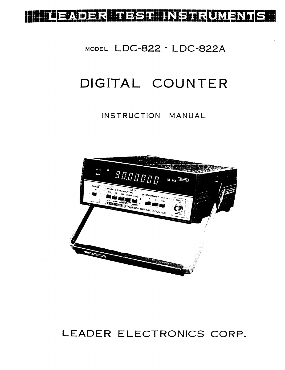
MovEL
LDC-822
:
LDC-822A
DIGITAL
COUNTER
INSTRUCTION
MANUAL
LEADER
ELECTRONICS
CORP.


Ay
LDC-822
-
LDC-822A
DIGITAL
COUNTER
Introduction
LDC-822(A)
is
a
digital
frequency
counter/timer
designed
to
measure
the
frequency
and
period
of
a
signal,
featuring
a
wide
frequency
range
10Hz—80MHz,
a
high
input
sensitivity
(20mV)
rms,
and
high
resolution
to
7
digits.
The
period
function
makes
the
unit
outstanding
for
video
tape
recorder
service
applications.
This
instrument
can
be
used
for
adjustment,
test
and
repair
of
audio
instruments,
AM/FM
radios,
TVs,
CB
radios,
computer
clocks,
amateur-radios,
electronic
watches,
and
musical
in-
struments,
etc.
The
LDC-822(A)
is
small
and
portable.
A
big
bright
fluorescent
display
assures
easy
readability
of
values.
The
green
display
does
not
induce
eye
fatigue
even
after
an
extended
period
of
viewing.
Readout
miscounts
are
reduced
by
zero-blanking,
unit-display
(kHz,
MHz,
mS)
and
overrange
display.
The
use
of
LSI
and
MSI
in
the
internal
circuit
assures
reliable
performance
and
less
power
consump
tion.
2:
Specifications/
Ratings
Frequency
Measurements
Range
Gate
time
Resolution
Accuracy
Period
Measurements
Range
Multiplication
Factors
Resolution
Accuracy
Input
Section
Input
sensitivity
Attenuator
Coupling
Input
impedance
Maximum
input
voltage
Time
base
Frequency
Accuracy
General
Specifications
Display
Operating
temperature
range
10Hz
—
80MHz
0.18,
1S,
10S
10Hz,
1Hz,
0.1Hz
+1
count,
+
time
base
accurac
y
100mS
—
1yuS
X10,
X100,
X1000
10uS,
1uS,
0.1uS
+1
count,
+
time
base
accuracy,
+
trigger
error
y
gs
20mVrms,
200mVrms,
2Vrms
(10Hz
—
80MHz)
1,
1/10,
1/100
AC
approx.
1IMQ2
10Hz
—
400Hz
100Vrms
400Hz
—
100kHz:
20Vrms
100kHz
—
80MHz
:
5Vrms
1OMHz
(crystal
controlled)
+5
X
10
©
(32°F
—
104°F)
(0°C
—
40°C)
7
digits,
7
segment
fluorescent
display
overflow
indication,
gate
indication
and
zero
blanking
©
0°C
—
40°C
(32°F
—
104°F)
Power
source
100V,
117V,
200V,
234V
+
10%
50Hz
—
60Hz
(Voltage-change
is
accomplished
by
change
on
tap
of
trans-
former)
Power
consumption
Approx.
1OVA
Dimensions
3"(H)
X
8”
(W)
X
10"(D)
excluding
knobs
and
legs
Weight
approx.
5
lbs.
Accessories
clip
cable
with
BNC
connector
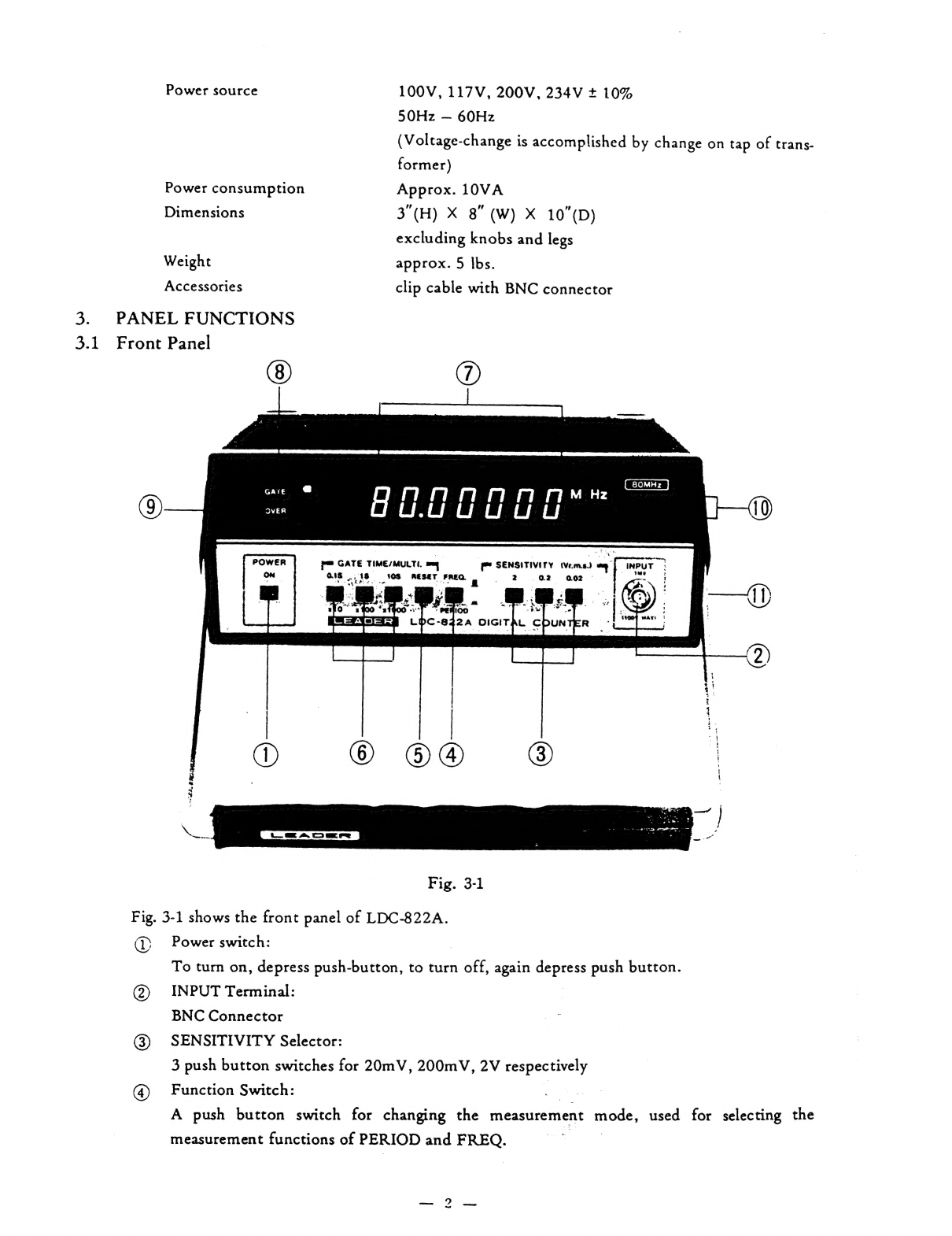
3.
PANEL
FUNCTIONS
®D
3.1
Front
Panel
POWER
ae
;
7
[ee
=
er),
‘
be
GATE
TIME/MULTI.
ENSITIVITY
(vems.)
oe
{
inPuT
p=
i
ae
|
pm
SENS
s
7
ae
.
PU
O1S
.,
18
108
RESET
FREQ.
2
02
ao2z
a
=
tt
ca
ae
Ne
:
Dee
4
:
a
2
2
ca?
;
i
;
,
:
oes:
as
ey
-
A
Bt
;
a
a”
ss
ws
ic
‘
r
_£
Pos
Sew
age
“Wi
|
=
.
:
a
:
1
280
=
x
4100
“2
>
(tOOF
mays
|
MENSSeW
LPC-842A
OIGITAL
CDUNTER
-
|
|
oO
©
©@®
®
Fig.
3-1
Fig.
3-1
shows
the
front
panel
of
LDC-822A.
Power
switch:
|
To
turn
on,
depress
push-button,
to
turn
off,
again
depress
push
button.
INPUT
Terminal:
|
BNC
Connector
SENSITIVITY
Selector:
3
push
button
switches
for
20mV,
200mV,
2V
respectively
©
Function
Switch:
=
A
push
button
switch
for
changing
the
measurement
mode,
used
for
selecting
the
measurement
functions
of
PERIOD
and
FREQ.
Oe
©
®&
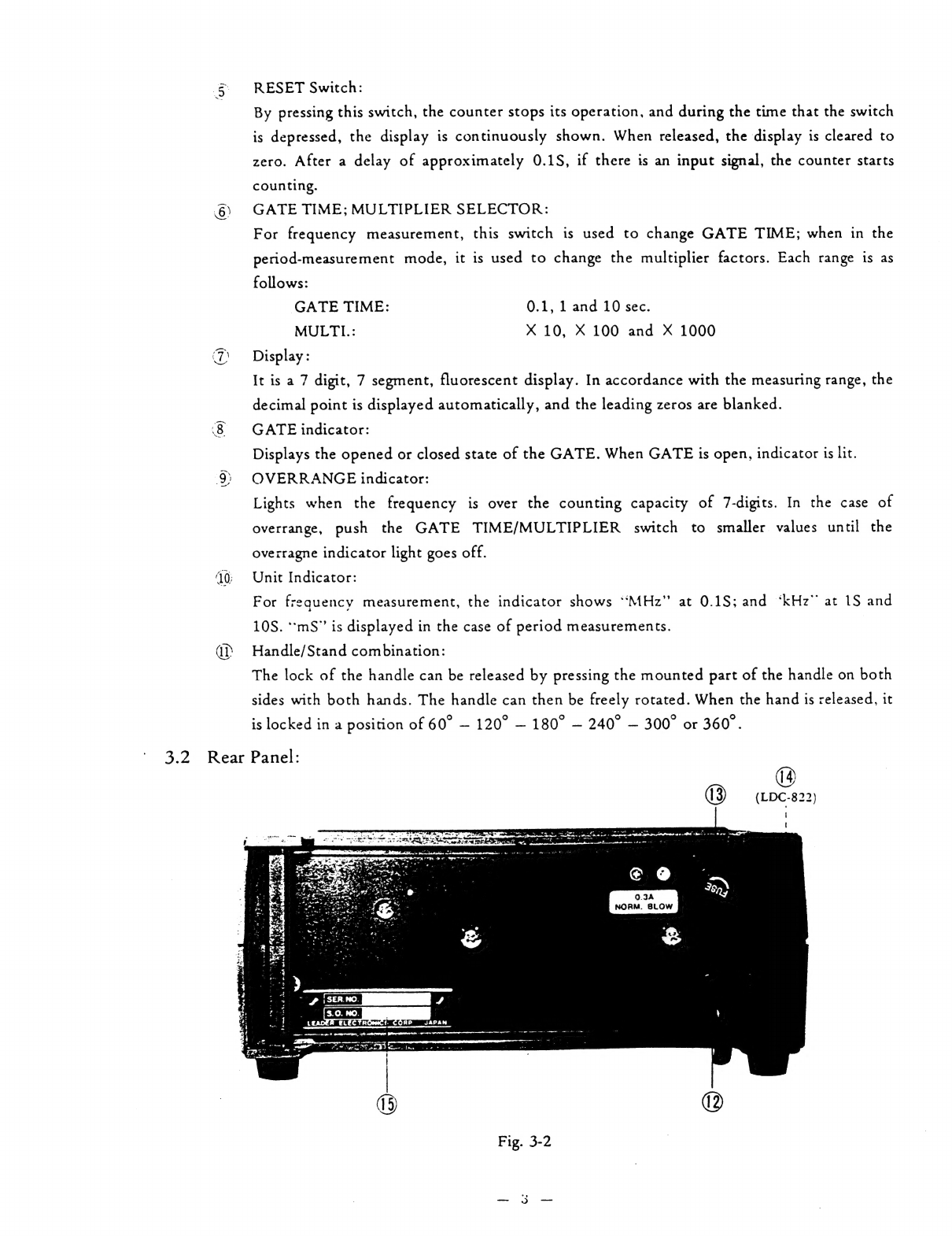
RESET
Switch:
=
By
pressing
this
switch,
the
counter
stops
its
operation,
and
during
the
time
that
the
switch
is
depressed,
the
display
is
continuously
shown.
When
released,
the
display
is
cleared
to
zero.
After
a
delay
of
approximately
0.1S,
if
there
is
an
input
signal,
the
counter
starts
counting.
6)
GATE
TIME;
MULTIPLIER
SELECTOR:
For
frequency
measurement,
this
switch
is
used
to
change
GATE
TIME;
when
in
the
period-measurement
mode,
it
is
used
to
change
the
multiplier
factors.
Each
range
is
as
follows:
GATE
TIME:
0.1,
1
and
10
sec.
MULTL:
X
10,
X
100
and
X
1000
(7)
Display:
It
is
a
7
digit,
7
segment,
fluorescent
display.
In
accordance
with
the
measuring
range,
the
decimal
point
is
displayed
automatically,
and
the
leading
zeros
are
blanked.
‘8
GATE
indicator:
Displays
the
opened
or
closed
state
of
the
GATE.
When
GATE
is
open,
indicator
is
lit.
9)
OVERRANGE
indicator:
Lights
when
the
frequency
is
over
the
counting
capacity
of
7-digits.
In
the
case
of
overrange,
push
the
GATE
TIME/MULTIPLIER
switch
to
smaller
values
until
the
overragne
indicator
light
goes
off.
40;
Unit
Indicator:
For
frequency
measurement,
the
indicator
shows
‘MHz’
at
0.1S;
and
‘kHz™
at
1S
and
10S.
‘mS’
is
displayed
in
the
case
of
period
measurements.
dP’
Handle/Stand
combination:
The
lock
of
the
handle
can
be
released
by
pressing
the
mounted
part
of
the
handle
on
both
sides
with
both
hands.
The
handle
can
then
be
freely
rotated.
When
the
hand
is
released,
it
is
locked
in
a
position
of
60°
—
120°
—
180°
—
240°
—
300°
or
360°.
3.2
Rear
Panel:
0.34
NORM.
BLOW
&
:
a
PNET,
oft
ITED
SPonnetanene
am
pene
eommanenanammaaemmnasimetemetsnnennn
etnies
aa
-~
~~
ar
Poe
pre
ee
a
eae
mat
Pewee
dime
60
t
(5
©)
Fig.
3-2

hon
13
™
(1g)
on™,
(
Power
cord
Fuse
holder
(contains
0.3A
fuse)
Stand
legs
(LDC-822)
There
are
four
legs
on
the
stand
for
keeping
the
LDC-822
in
the
vertical
position.
The
power-cord
can
be
coiled
when
not
in
use.
Label
3.3,
Diagram
of
the
base
Fig.
3-3
d@
With
a
screw
driver,
trimmer
control
adjustments
of
the
reference
frequency
oscillator
can
be
made.
For
procedure,
refer
to
section
6
—
Maintenance.
d7
Rubber
feet
4,
Operating
Instruction
4.1
Precautions
in
use
1.
to
In
connecting
the
instrument
to
the
device
(to
be
tested),
particularly
in
an
internal
connection,
remove
all
AC
power
to
the
device,
and
remove
the
cord.
After
discharging
all
charged
capacitors,
connect
the
cable
for
measurement,
thus,
the
danger
of
an
electrical
shock
can
be
minimized.
Take
the
same
care
in
disconnecting
the
input
cable.
Use
AC-power
source
of
LDC-822(A)
at
50
—
60Hz,
within
10%
of
rating
voltage.
Caution:
Excessively
large
or
small
AC-voltages
may
induce
erroneous
operation.
In
replacing
the
fuse,
use
the
designated
0.3A-fuse.
Avoid
all
the
severe
mechanical
shocks
to
crystal-oscillator
or
fluorescent
indicators.
4.2
Fundamental
Operation
1.
Oe
eS
Disconnect
the
input
cable
of
the
LDC-822(A).
Connect
the
AC-power
cord
to
the
proper
AC-power
source.
Set
POWER
switch
to
the
ON
position.
Set
the
function
switch
to
FREQ.
Set
the
SENSITIVITY-selector
to
2V.
-

4.3
6.
Putthe
GATE
TIME
Selector
at
0.1S.
Confirm
the
display
of
‘“0.00000MHz.”
There
is
no
display
on
the
left-ward
1st
digit
of
the
decimal
point.
The
GATE
indicator
is
lighted
for
0.1S
while
the
gate
is
open,
and
disappears
for
0.1S
while
the
gate
is
closed.
7
Set
GATE
TIME
selector
at
1S,
in
this
case,
the
display
shows
0.000kHz,
and
GATE
indicator
shows
the
repeating
1S
light-on/0.1S
light
off.
8.
Press
the
10S
GATE
Selector.
Display
of
left-most
2
digits
disappears,
revealing
0.0000kHz,
and
GATE
indicator
repeats
10S
light-on/about
0.15
light-off.
9.
Set
the
FUNCTION-switch
to
PERIOD.
10.
Use
the
“MULTI”
scales,
and
confirm
the
display
as
shown
in
Table
4-2-1.
In
the
case
that
the
displayed
figure
shows
other
than
0
(zero),
or
when
GATE
indicator
is
lighted,
push
the
reset
switch,
then.
GATE
indicator
disappears
(gate
is
closed),
and
the
display
shows
as
in
Table
4-2-1.
MULTI
Display
0.00__mS
X100
0.000
mS
0.0000
mS
Table
4-2-1
=
11.
In
the
above
6—10
OVER-flow
indicator
always
shows
light
off.
Input
Connections
Connect
BNC
Connector
of
the
accessory-cable
to
the
input-terminal.
Connect
the
ground
—
negative
side
of
the
clip
to
the
(common)
of
the
device
under
test.
connect
the
positive
hot
side
to
the
test
point.
The
input
AC
only
(DC
blocked
by
0.1uF
capacitor).
The
maximum
allowable
voltage
of
the
AC
component
of
the
input
signal
depends
on
frequency,
the
values
are
as
follows:
10Hz
—
400Hz
100Vrms
or
280Vp-p
400Hz
—
100kHz
20Vrms
or
56Vp-p
100kHz
—
80MHz
5Vrms
or
14Vp-p
The
maximum
voltage
of
the
DC
component
of
the
input
signal
is
+
100V
DC.
When
the
input
signal
is
not
a
continuous
sine-wave
or
is
modulated,
the
following
values
are
the
maximum
allowable
AC
input
voltages
permitted
in
accordance
with
the
frequency
chart
below.
10Hz
—
400Hz
250Vp-p
400Hz
—
100kHz
56Vp-p
100kHz
—
80MHz
14Vp-p
CAUTION
NOTE:
Caution
should
be
taken
not
to
get
an
electric
shock
when
connecting
or
removing
the
input
cable.
High
voltage-circuits
and
horizontal
output
pulses
of
flyback
transformers
in
TV-sets
generate
excessive
voltages.
The
LDC-822(A)
could
be
damaged
by
exceeding
input
limitations.
Therefore,
never
make
a
direct
connection
to
these
circuits.

4.4
The
input
impedance
of
this
instrument
is
approx
IMQ)
and
shunted
by
approximately
30pF.
The
input
cable
has
a
distributed
capacity
of
approx
7OpF.
This
total
(100pF)
should
be
considered
when
making
critical
measurements.
Note:
Do
not
connect
the
input
of
LDC-822(A)
to
a
high
impedance-point
of
the
device
under
test.
The
parallel
effccts
of
this
1M{2/100pF
combination
affects
the
operation
of
the
circuit
being
tested.
Setting
of
input
sensitivity
1)
Input
sensitivity
and
noise
The
input-sensitivity
of
LDC-822(A)
can
be
selected
from
0.02Vrms,
0.2Vrms,
or
2Vims,
in
order
to
measure
input
signals
of
wide
voltage-ranges.
When
a
large
signal
is
applied
to
the
input
at
the
higher
input-sensitivity,
the
noise
included
in
the
input
signal
may
induce
miscounting.
In
this
case,
reduce
the
input
sensitivity
to
the
appropriate
input
range
as
listed
in
Table
4-4-1.
This
minimizes
errors.
Range
of
input
voltage
|
Input
sensitivity
of
counter
0.02Vrms
0.02
—
0.2Vrms
0.2Vrms
_
0.2
—
2Vrms
2Vrms
2
—
20Vrms
Table
4-4-1
2)
Measurements
of
Modulated
Signals
Modulated
signal
VH
VH
:
Input
Sensitivity
of
counter
Fig.
4-
4-2
As
seen
in
the
above
Fig.
4-4-2,
in
order
to
measure
the
frequency
of
modulated
carrier-wave,
if
the
voltage
of
highest
modulated
part
is
greater
than
the
input
sensitivity
VH
(0.02Vrms),
it
is
then
possible
to
count
the
carrier-wave.
4.5
Frequency-measurement
Set
the
function-switch
to
FREQ.,
apply
signal
to
the
input
terminal.
The
measuring
range
is
10Hz
—
80MHz.
By
setting
the
GATE
time
to
the
values
shown
in
Table
4-5-1,
measurement
can
be
done
at
the
maximum
resolution
without
overrange.
|
10Hz
—
999.999kHs
|
0.0100kHz
—
999.999kHz
10Hz
—
9999.999
kHz
|
0.010kHz
—
9999.999kHz
10Hz
—
80.00000MHz
0.00001MHz
—
80.00000MHz
Table
4-5-1

4.6
In
measuring
the
trequency
of
10Hz
—
kHz
at
a
high
resolution,
period-measurement
is
more
suitable.
Period
measurement
1)
2)
Set
the
function
switch
to
PERIOD,
and
apply
the
signal
to
the
input
terminal.
The
measuring
range
is
100mS
—
0.001mS
(1
uS).
Period-measurement
is
suitable
for
accurate
measurement
in
the
frequency
range
of
10Hz
—
1kHz.
By
setting
the
MULTI
and
PERIOD
as
listed
in
Tables
4-6-1
and
4-6-2,
more
accurate
measurements
can
be
accomplished
within
a
short
time
and
longer
numerical
display
measurement
results
in
amore
accurate
measurement.
When
the
measuring
time
is
within
1S
—
0.1S,
LOHz—100Hz
X10
100.00mS
—
10.00mS
Iktis
—
10kHe
|
ImS—
0.1mS
Table
4-6-1
When
the
measuring
time
is
within
10S
—
1S.
10Hz
—
100Hz
100mS
—
10mS
X100
100.000mS
—
10.000mS
100Hz
—
ikHz
10mS
—
1mS
X1000
10.0000mS
—
1.0000mS
Table
4-6-2
Measuring
accuracy
The
accuracy
of
period-measurement
can
be
expressed
as
follows:
Accuracy
=
+1
count
+
trigger
error,
time
base
accuracy
...
Equation
4-6-1.
In
the
above
equation,
the
most
important
factor
is
the
trigger-error.
Trigger-error
occurs
with
the
overlapped
signal
noise
and
noise
in
the
counter.
During
the
measurement,
when
the
display
fluctuating
range
is
within
+1.
the
error
can
be
regarded
as
+1
count.
If
it
is
over
+1
count,
it
may
be
trigger-error
or
alteration
of
the
input
signal.
As
a
checking
method,
when
the
input-sensitivity
of
counter
or
input-voltage
is
set
to
higher
values.
if
the
variable
range
becomes
less,
it
can
be
judged
as
trigger
error.
In
order
to
reduce
the
effect
of
input
signal
noise
the
trigger-error
can
be
reduced
by
raising
the
input
voltage
or
by
rectifying
the
input-wave
into
rectangular
wave-form
applying
to
LDC-822(A).
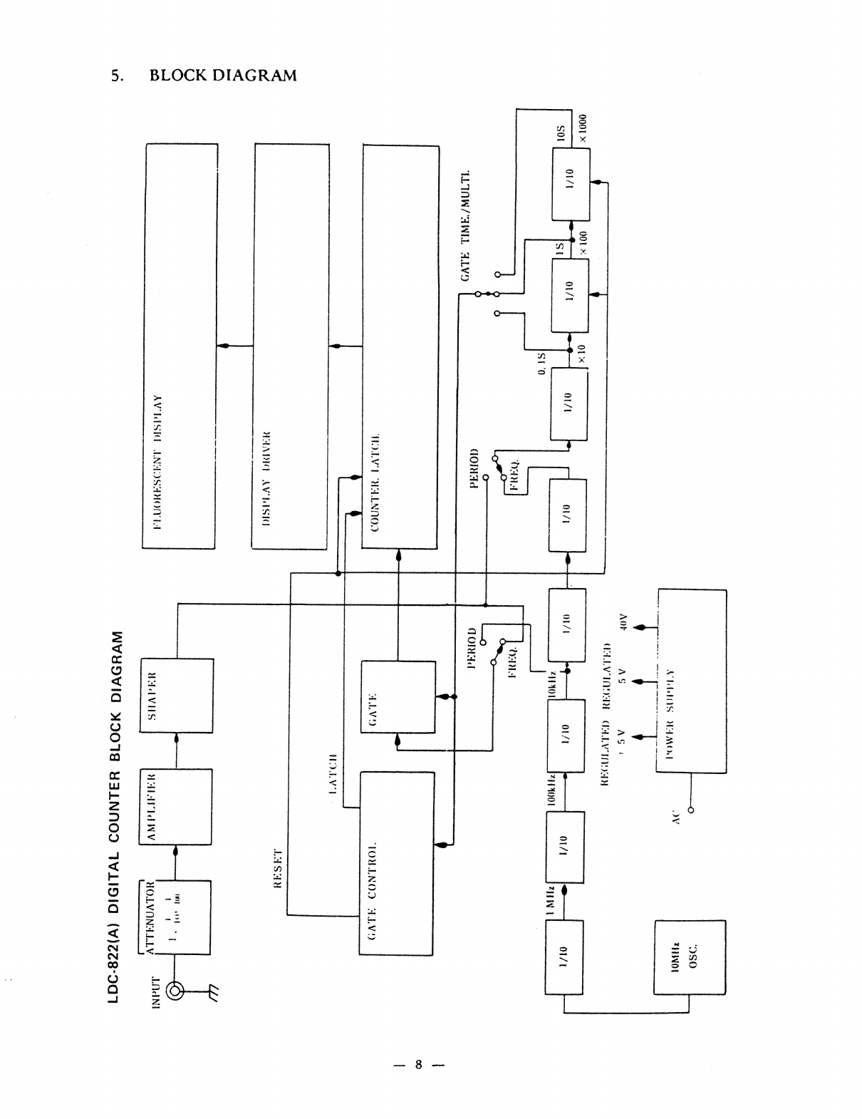
BLOCK
DIAGRAM
>:
‘OSO
THWOL
JV
Nd
UE
MO
=
ae
a
AOF
AG
AS
|
CAE
LWIADSRE
CELL
W
LQ
OaM
000T
x
OI
x
:
O1/1
oO/t
Ol/t
OI/1
SOl
“HAO
“HOOT
7HIN
ORM
Coon)
domad
TLTAW/SAWIL
ALV9O
HOLLY
E
CUALENAOO
TORLNOD
ALVD
LASAY
HWAARIO
AW
PEASIO
HO
ent
iy
{
l
YOLVANALLV
Na
ed
LAANI
AVIASIO
NAOSAMOMNTA
Usd
VES
WAAL
NV
WVYSVIG
MOOT
HALNNOD
IVLIDIG
(v)zZzZ8-907

6.
MAINTENANCE
1.
Tocalibrate
or
make
correction
to
the
standard
oscillator.
A
standard
oscillator
with
an
accuracy
greater
than
+1
X
10%
is
required
for
calibration.
Apply
the
output
of
standard
oscillator
to
the
input-terminal
of
LDC-822(A);
measure
the
frequency.
A
normally
operating
counter
displays
IMHz
or
10MHz.
If
you
read
other
than
1MHz
or
10MHz,
adjust
the
trimmer
capacitor
with
the
screw
driver
through
the
hole
for
adjustment
provided
at
the
base
of
the
LDC-822(A),
in
order
to
make
exact
accurate
display.
2.
The
LDC-822(A)
has
been
designed
for
easy
maintenance
and
high
reliability
by
employing
LSI/MSI
IC’s
for
the
digital
and
power-source
sections
of
this
instrument.
3,
Lf
the
instrument
fails
to
perform
in
the
manner
specified
herein,
write
or
call
your
nearest
Leader
office
for
factory-trained
service.
For
safety
reasons,
and
to
prevent
damage
to
the
instrument,
DO
NOT
REMOVE
the
unit
from
the
case.

a
RS
SALONS
RRemrseeiaccteranectees
“SP
Naa
3
]
ro]
0-
S6bYSz2
4m00
+
1
ae)
UNI
»
.
ale
iz2(
VL)
Nz
tw
ne
pa
RE
gston
on
matte’
oon,
se
ae
i
ne
BesiSiBasisS!]
4d
ts
CDH
Cpe
Eeyore
Sn
3@NL
YOLVIION!
eal
a,
20
95200013
mOO!
Zp
tal
VZeC
362
oa
iN3
YON
OQ
Lt9
[+
veee
eee
a
a,
:
3eEuSz
wee
BY
SuolLb
tO
(3
Tis
ee
me
rte
ree
=
ee
ec8-
901
lapow
SHLVWAHOS
d31V3H
\
s
ake
Tes
ae
D
:
ONIN
HadWAr
Undb
rH
O-
sez0sz
vay
HLIMS
¥am0d
=
ve'0
oF
3sng
atii
ALM
9
ozs
2020
UNL?
202%
2
~
@-
ww
a--
60Ct-1
VOLb
Um!
9eu
Sey
VL829S2
69
t
(S316
94
Oe
|
es
Sty
Ns
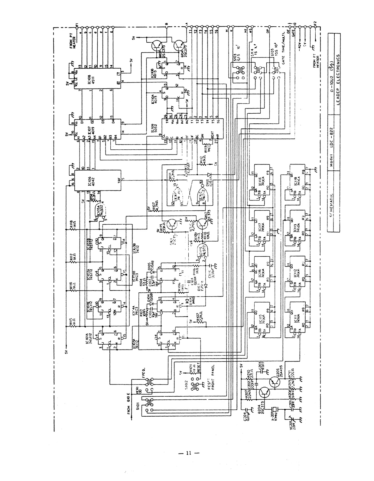
SOINOd1L93703
d30V31
ee
ee
en
Re
ee
ee
A
ne
ee
ee
te
ne
ee
eee
t
“MWA/3NIL
349
f
|
esor
f=
©
bs:
scisf_
'
end
toll
;
2%
Si
oD
Oo
AS
On
6
a
@
|
|
Re
ee
|
ee
eee
wae
nee
©
ee
ee
ee
ee
228-
20)
we
Ba
es
ee
1apow
ee
me
ee
——
JIiVviaH
>
Vi
VOSuL
aT)
f
VOGEL
30)
|
VINVWd
LNOd4
135
]4d
eer
J
“35
cue
yw
5
ieee:
ie
Od
Ji
/egswOs
LY
wg
SPA
sun
WAZ
OWN
:
Ques
WtO0
+)
4
pay
ey
i
aan
nal
Cae
je
NO
—
’
SL
IG2
ite
ths
att
Dy
t
‘
S
und
MS
At
sesisiZy
HIKE
OL
GOIOT
©
Ot?
pg
Uw
vOtmM
chled
€7ivd
€7tbl
as
Mol
Oputd
Ve
tl
—ill—
REE
BRSSRRAees
Bas
"LEADER
TEST
INSTRUMENTS
|
|
LEADER
ELECTRONICS
CORP.
2-6-33
TSUNASHIMA-HIGASHI,
KOHOKU-KU,
YOKOHAMA,
JAPAN.
PHONE:
(045)
541-2121
TELEX:J47780
JPLEADER
LEADER
INSTRUMENTS
CORP.
380
OSER
AVENUE,
HAUPPAUGE,N.Y.
11788
U.S.A.
PHONE:
(516)
231-6900
TELEX:
510-227-9669
LEADER
HAUP
sa
a
a
83071.
SKM
Printed
in
Japan.
This manual suits for next models
1
Table of contents
Other Leader Electronics Corp. Cash Counter manuals


Popular Cash Counter manuals by other brands

Nautilus Hyosung
Nautilus Hyosung MoniMax 5100T Operator's manual

Cashmaster
Cashmaster Omega 230 user manual

Quick
Quick CHC1103 Manual of installation and use

AlphaLab
AlphaLab Precis-Ion AIC3Pro quick start guide

Line Seiki
Line Seiki E60 Series instruction manual

Cashmaster
Cashmaster Sigma 105 Frequently asked questions


