Atek ALC-94 Series User manual

1
Housing
Dimensions
96 x 48 x 88 mm
Display
Single Line , 6 Digits 14mm LED Display ( RED color )
Display Range
-99999….999999
Weight
300 gram
Box
Suitable for flush-panel mounting
Relative Humidity
80% up to 31°C decreasing linearly 50% at 40°C.
Operating Temperature
0...50 ° C
Storage Temperature
-10...60 ° C
Protection Class
IP 60 front panel, IP 20 rear panel
Electrical Characteristics
Power Supply
24V AC/DC 50/60 Hz.or 85-265 VAC 50/60 Hz.
Power Consumption
Max. 5,5VA - 4.4 W
Connections
2,5 mm² screw-terminals connection
Inputs
Counting Frequency
600 KHz (Quadrature mode)
Input Channels
A, B counting inputs; Z external reset input; external HOLD input
Z (Reset Input)
Selectable in Rise or Fall edge triggering (From software)
HOLD Input
Selectable in Rise or Fall edge triggering (From software)
Polarity Input
Programmable, npn or pnp for all inputs
Outputs
Control Ouutput
4 Relay: 250 VAC, 3 A (for Resistive load) COM, NO and NC
Sensor Supply Output
5 VDC or 12 VDC, 100 mA
Digital Out
RS-232 Serial Interface
WARNINGS
94x48 mm dimensions
600 KHz reading speed
6 digit display
Functional External Z input
Functional HOLD input
Quadrature mode up –down counting
2 or 4 couple contact relay output
Set-1 can be set related with Set 2
Optional factor value (between 0,00001 and 999999)
Optional decimal point between 1. and 5. digits
5 VDC or 12 VDC encoder power supply
11 various output control mode
OFFSET value is adjustable
Password Protection
1. Fallow the instructions and read the manuel before conection and using the device.
2. Check the power supply type before giving energy.
3. Mount the device to the panel robustly againts to the drops, vibration and shakings during utilization.
4. Make the sensor connections while the energy off. Never change the connections while the energy is on.
5. Keep Away from the high voltage.
6. Don’t expose to the sunbeams and heating source directly in the utilization place.
7. ALC94 Industrial Control Device proper only for room conditions, don’t use outer environment.
8. Clean the device only with a moist duster, never use water, thinner ect...
9. Adapt the relays to the given technical relay output values.
10. There is no part for replacing or repairing, please call the service in case a defect.
HIGH SPEED UP / DOWN COUNTER
ALC94

2
Button Functions
In ALC94 device the buttons have two functions:
Programme Mode: Function for programming.
Operation Mode : Function for operating.
1. PROG Button (Programme Mode): To enter the MENU parameter and save the entered parameter.
2. LEFT Button (Programme Mode): To change the decinal parameter while entering the parameter value.
3. UP Button (Programme Mode): To transition in the MENU and increase the value of the sellected parameter.
Operation Mode: To see the max measured value.
4. DOWN Button (Programme Mode): To transition in the MENU and increase the value of the sellected parameter.
Operation Mode: To see the min. measured value.
5. RST Button (Programme Mode): To escape without saving the entered value.
Operation Mode: To reset the value on the display.
6. Out-1 output condition LED: Signs by Out-1 output relay gets power.
7. Out-2 output condition LED: Signs by Out-2 output relay gets power.
8. Out-3 output condition LED: Signs by Out-3 output relay gets power. (Optional)
9. Out-4 output condition LED: Signs by Out-4 output relay gets power. (Optional)
ALC-94 Series
FRONT PANEL DESCRIPTION
FRONT PANEL USAGE
Entering the value to numerical parameters:
Press
RST
and enter the programme, the right hand digit will blink. Using the and it is selected
the parameter which is requested to change its value, than press again and save this value, it is showed next digit
now. Finally, it is showed , using and and select the (+) positive or negative (-)
If you request return back without saving the value you should press button.
Entering the value to string parameters:
Press and enter the programme, using the and select the parameter which you request to change its
value, than press again and save this value.
If you request return back without saving the value you should pres button.

3
SOCKET CONNECTION
ALC-94 Series
DIMENSION and PANEL CUT-OUT :
Panel cut-out:

4
While the device is holding on operation mode to pass to programing mode press and hold on button and press button.
Enter the menu after seing “on the display. is flushing and menu on the display firstly.
If the password is activated the device asks for password while changing the parameter values. If you enter wring password
the device gives FALSE masage. You can enter the menu but you can’t change the values. If you enter the right password the
device gives TRUE masage, you can change the values.
Select the prefered menu by UP Down buttons . Press button to enter menu which you will change. To change the value
press PRG again. Use UP DOWN buttons to change values. UP button for increase and DOWN button to decrease. To save
the value press PRG.
ALC-94 Series
PROGRAMMING MENU
.
Enter the password.
.
RST
RST
RST
Set-1 Set-2 menus are used for presetting set values. (set-3 or set-4 are also used if they exist. Each
menu controls aan output. When the given set value reached the related relay is become activated
and the LED of the relay signs. There are different output functions. There outputs will be descripted in
OUTPUT MENU.
To enter the SET menu first enter the Programme menu. To enter the programme menu press and
hold PRG button and press RST button. You will see the Set-1 menu. To find Set-2 Set-3 and Set –4 the
UP DOWN buttons are used. To change the Set-1 value press PRG. You will see the present SET value
on the display. When you press to PRG button again the last digit will flashing. You can set the
intended value by using UP DOWN buttons. To pass to other digit press LEFT button. The digit will pass
left for each LEFT button pressing. To change the point place POINT menu is used. This subject will
descripe in POINT MENU. After presetting the intended value press PRG to save the value. If you
would like to leave without saving press RST button. You can change the other set values by this way.
PRESET SET VALUES ( Set )
Output menu allows he different outputs regarding to set values. There are 11 different output types.
The output types are exit in the graphics section. To select any output mode press and hold PRG and
press resent button. You will be in programme mode. Find the OUTPUT MENU by using UP-Down
buttons.Press to PRG buton to see the menu. Press to PRG button again. The menu members will be
flashing when you press to PRG again. You can select the MODE by using UP DOWN buttons and you
may save it by pressing PRG button.
The relay activation time can be controlled by Tout menu. If the time is 0 (zero ) there will be written
HOLD on the display. It means the relay will be activated when the relay value is above the setted
value. To enter output time press and hold PRG button and press to RST button. tout-1 tout-2 tout- 3
tout-4 menus can be found by UP DOWN buttons. To display the Menus press PRG button.When you
press to PRG button again the values will be flashing. The value can be set by UP DOWN buttons
Relay Output Time ( tout )
Relay Output Menu ( Output )
Flushing Prog writing

5
ALC-94 Series
You may eneter the hysteresis values by this menu. This menu is for blocking the relay flickers. After
the value which is setted, relays activate contacts or reactivates the contacts. There will not be any
action during hysteresis. So the negligible value should be entered. To change the hysteresis values
Hys-up and Hys-dn menus are used. Hys-up values are active while pass over the set values, hys-dn
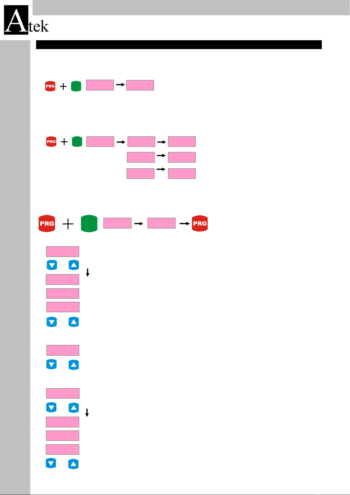
values are active while dropbelow the set values.To set the hysteresis values press and hold Prg button
and press Rst button. Find the menus hys-up and hys-dn by UP DOWN buttons. Press Prg button to
flashing the first digit. Enter the value by UP DOWN buttons. To pass the other digit use LEFT button.
Press Prg to save the value.
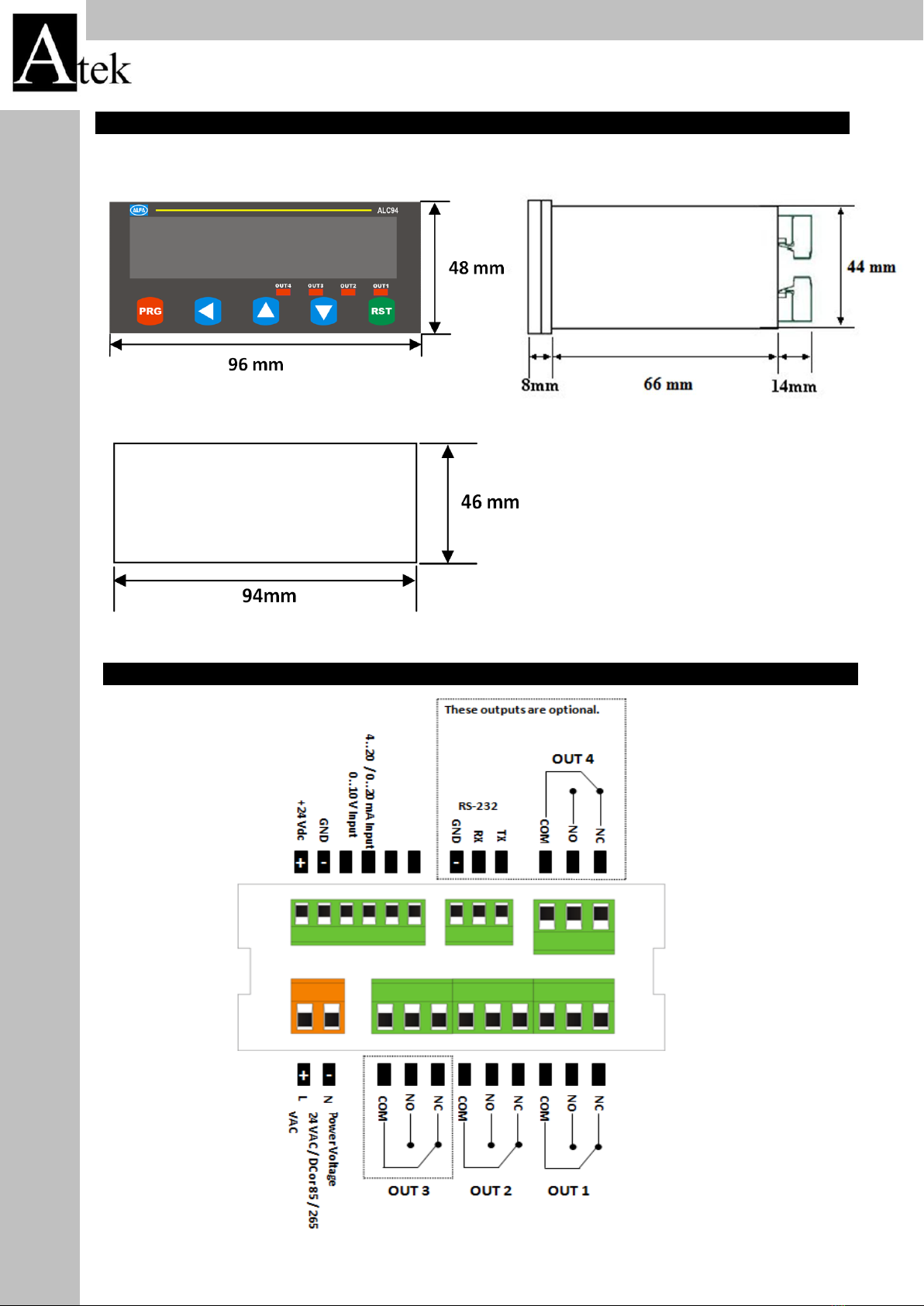
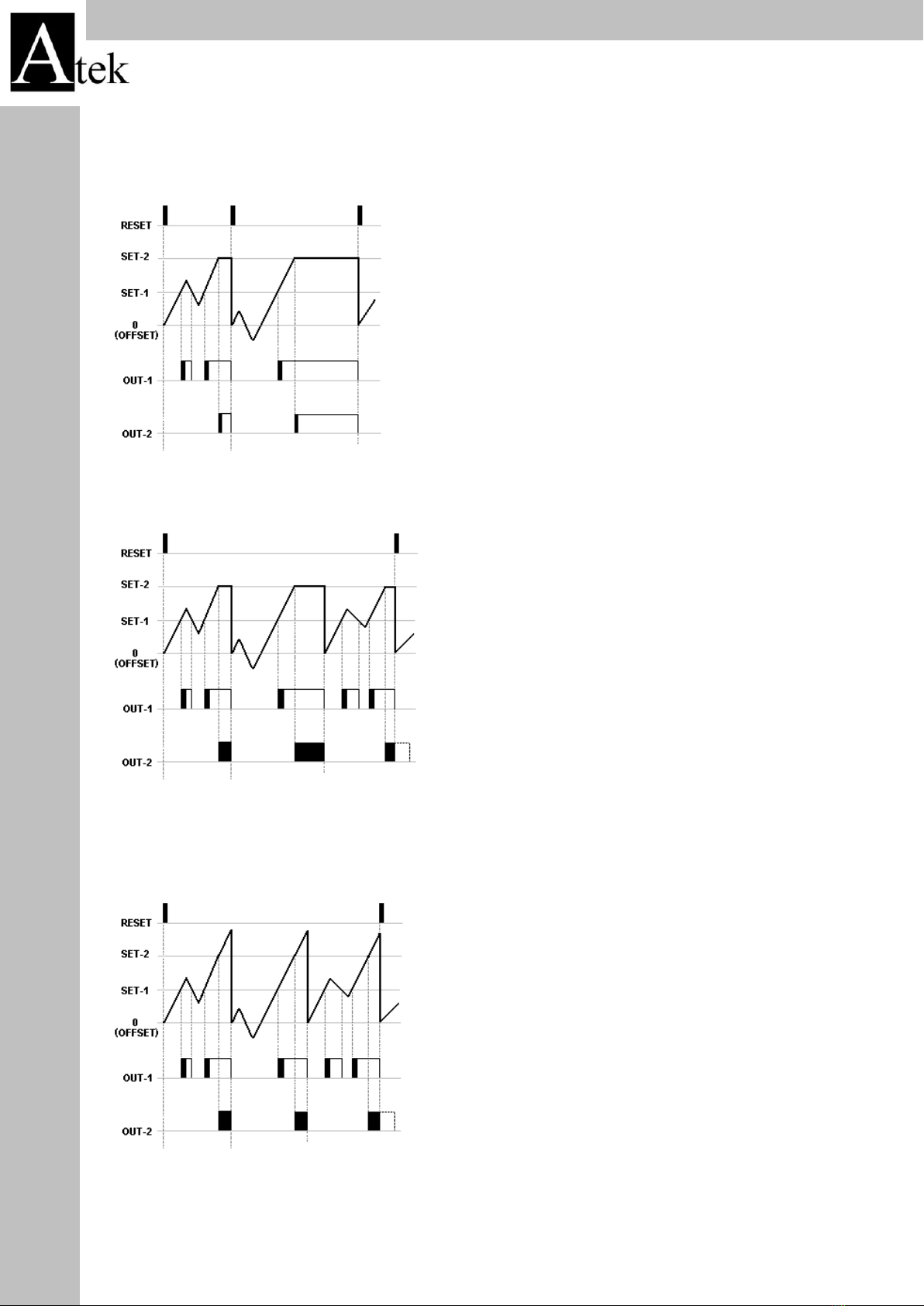
Relay Output Commands ( out )
Setting Hysteresis ( hys-up, hys-dn )
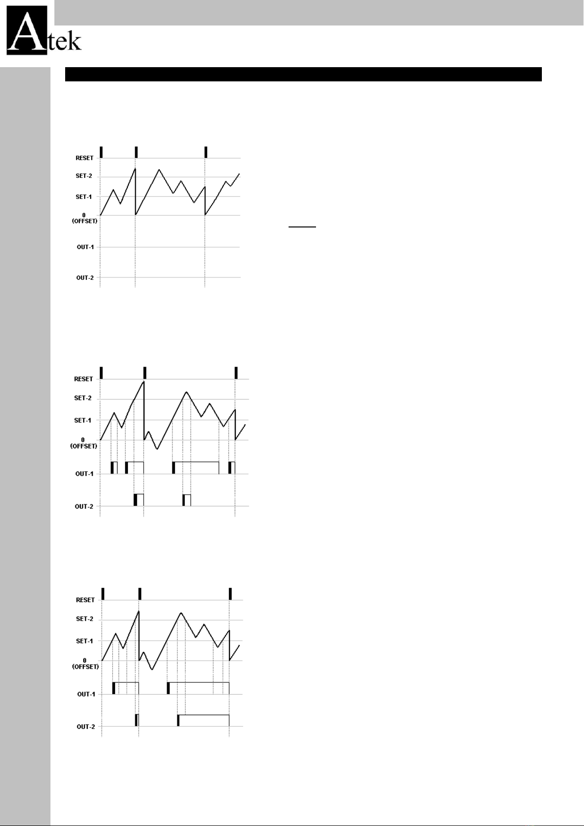
Out-1 ve out-2 out-3 out-4 menus specify the relay positions. In Nclose
section relay will be passive when the set value is reached the will be
active.In Nopen sectin the relay will be active and when the set value is
reached it became passive
Const menu allows to set constant factor for displaying the different resolutioned sensor as intended
values. You can determine display value for each edge or pulse. For example for 25 micron resolution
sensor 0,0025 value will be seted in CONST menu. By this way when the sensor goes 25 mm you can
see it as 25 on the display.
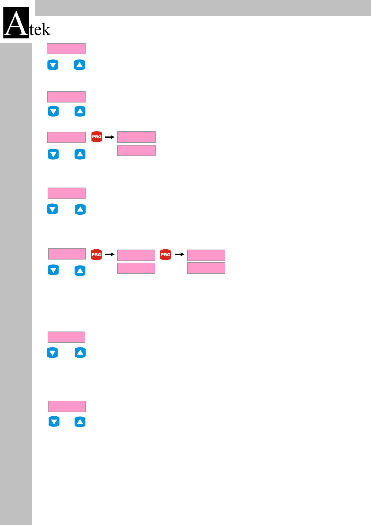
Menu if you press prg button you will see the setted value on the display. If you press to PRG button
again the first digit will be flashing. You can change it by UP DOWN buttons. To pass to the other digit
by LEFT button. After setting the intended value press to PRG button to save the value. To return to
operation mode without saving the value press RST.
Setting Constant Factor
The accuracy of the values on the display adjusted by this command. By changing the place of the
point the accuracy of the value can be selected. Also the SET and HYSTERESYS manus poing place can
be adjust by this command. To adjust the point menu press and hold PRG button and press to RST
button. POINT menu can be found by UP DOWN buttons. In POINT Menu when you press to PRG
button you can see the setted point possition. Press to PRG button and the value will be flashing. By
Up Down buttons you can select the point possition. Pres PRG button to save the possition
Point Place Selection ( Point )
If you press Rst button or if there is a signal Z input the device return to the setted offset value. If the
offset is 0 (zero) when you press to Rst button you see 0 (zero) on the display. Press and hold Prg
button and press Rst button.Find the Offset menu by UP DOWN buttons.
Press Prg to see the menu. Press Prg to make flushing the values.Enter the value by UP Down buton
and pres PRG to save the value.
.
.
This menu is used for activating the RST buton on the front panel. In active
condition in operation mode if you press RST button the displayed value is
reseted or returned to the OFFSET values. To activate the RST button press
and hold PRG button press RST button to turn to programme mode.
If you activate the Z input, you can reset the device by an external encoder Z
signal or swtich . There is 3 options as rise, fall and none.
Activate the Z input and select which edges will be count. Rise or fall. If you
don’t use Z input select none option.
Setting Offset Value ( offset )
ZERO By Reset Button ( Rst btn )
Activating Hold Input ( Hld.inp )
Find the Rst.btn menu by UP Down buttons. Press Prg button to display the menu contents. Press Prg
button to make flashing the selections. There is options. RESET and ACTIVE. If you select RESET it will
be active. If you select NONE it will be passive. Save the option by pressing Prg button
To activate the Z input press and hold Prg button. Find the Rst.inp menu by UP Down buttons. Press
Prg to display the menu. Press Prg again. The options will be flashing. Select the option by UP Down
buttons and press Prg button to save

6
ALC-94 Series
.
If the HOLD input is active the value on the display is frozen. Witout cutting the signal in the HOLD input
the device will not count when the HOLD input is active.
.
To activate the Hold type press and hold Prg and press Rst button. Find Hld.typ menu by UP DOWN
buttons. Press Prg to see the menu. Press Prg again to flashing the options. Select the option and press
Prg button to save the setting
.
Press and hold Prg button and press RST button.find Snstype menu by Up Dpwn buttons. Press Prg
button to display the menu.Press Prg again to make flashing the options. Select the intended option by
Up Down buttons and save the option by pressing Prg button
.
.
It is used for selecting the edge counting numbers of A, B signals of the encoder. Counting options are
1,2, or 4. If the incremental encoder is connected to see the value in pulse type select 1 . When a linear
encoder connected to the device to make a high resolution measurement 4 option will be better
(quadrature mode). To change the edge counting option, press and hold Prg button and press Rst
button. Find the Cnt. Typ menu by UP DOWN buttons. Press Prg to see the menu. Pres Prg again to
make flashing the options.
Change the options by UP DOWN buttons. Press Prg to save the selected option.
Activating Hold Input ( Hld.inp )
Hold Type Selection ( Hldtyp )
Selecting Sensor Type (NPN/PNP) ( Sns.typ. )
Edge Counting Option ( Cnt.typ. )
So it will be beneficial to save the important settings. The device asks you for a password to return to
factory settings. It is 454 To restore the factory settings press and hold Prg button and press Rst
button. Find Fac.def menu by UP DOWN butons. Press Prg to see the options. There is YES and No
options in the menu. Press Prg again to make flashing the options. If you press to yes option the
device asks you the password. The password sets by UP Down buttons and use LEFT button to pass to
other digits. Press Prg to save the return to the factory settings.
Restoring Factory Settings ( Fac.def. )
Factory menu used for restoring factory settings. All the settings will be changed by this menu. So it
will be beneficial to save the important settings. The device asks you for a password to return to
factory settings. It is 454. To restore the factory settings press and hold Prg button and press Rst
button. Find Fac.def menu by UP DOWN butons. Press Prg to see the options. There is YES and No
options in the menu. Press Prg again to make flashing the options. If you press to yes option the
device asks you the password. The password sets by UP Down buttons and use LEFT button to pass to
other digits. Press Prg to save the return to the factory settings.
Recording When The Energy is OFF ( Record )
Password Protection ( Protec )
Factory menu used for restoring factory
settings. All the settings will be changed
by this menu.
The used sensor can be selected by this menu. According to output
type of the sensor NPN veya PNP selection allows working with
different sensors

7
Output - 0:
Output-1:
Output-2:
Output-1:
If outmode is selected equal to “0” the outputs don’t run.
When the counting value reachs to Set-1, the OUT-1 turn
on and also reachs to Set-2, the OUT-2 turn on. Even if
the decrease down the Set values, the Outputs don’t
turn off.
Only if the RESET comes, the outputs turns off.
When the counting value reachs to Set-1 value, Out-1 turn
ON and also reachs Set-2 value, Out-2 turn ON.
Out-1 and Out-2 keeps on state in following condition:
Counting Value ≥ Set-1
Counting Value ≥ Set-2
NOTE:
It must be following conditins for all Output modes;
OFFSET ≤ SET-1 ≤ SET-2
OUTPUTS
ALC-94 Series

8
Output-3:
Output-4:
Output-5:
When the counting value reachs to Set-1, the OUT-1
turn on and if decrease under to Set-1 it’s turn off.
When the counting value reachs to Set-2, the OUT-2
turn on and the counting value is held (namely it
doesn’t count).
If the RESET comes, the outputs turns off.
It is Autoreset mode. In this mode OUT-1 depend on
the OUT-2. It should be enter the TOUT-2 is time and
the TOUT-1 is HOLD. Namely, when the counting value
reachs to Set-1, the OUT-1 turn on and if decrease
under to Set-1 it’s turn off. When the counting value
reachs to Set-2, the OUT-2 turn on and the counting
value is held.
The counting value and outputs will be auto-reseted in
the end of the TOUT-2 time.
It is also Autoreset mode same as Output-4
The difference is the counting value isn’t held, namely
after reached to Set-2, the instrument continue to
count.
ALC-94 Series

9
Output-6:
Output-7:
Output-8:
When the counting value reachs to Set-1, the OUT-1 turn
on and also reachs to Set-2, the OUT-2 turn on. Even if
the decrease down the Set values, the Outputs don’t
turn off unless the counting value reach to OFFEST value.
If the RESET comes, the outputs turns off.
When the counting value reachs to Set-1, the OUT-1 turn
on and if it decrease under the Set-1 OUT-1 turns off .
When the counting value reachs to Set-2, the OUT-2 turn
on. Even if the decrease down the Set values, Out-2
doesn’t turn off unless the counting value reach to
OFFEST value.
If the RESET comes, the outputs turns off.
The OUT-1 keeps on until the counting value reachs to
SET-1. When the counting value reachs to SET-1, OUT-1
turns off and when it reachs to Set-2, OUT-2 turns on.
If the RESET comes, the outputs turns off.
ALC-94 Series

10
Output-9:
Output-10:
In this mode it should be enter the value to TOUT times.
The Out-1 keeps on during the TOUT-1 time in every
pass of the counting value at Set-1. The state of Set-1 is
same as the Set-2.
If the RESET comes, the outputs turns off.
In this mode it should be selected the TOUT parameters
as HOLD.
The OUT-1 keeps on until the counting value reachs to
SET-2. When the counting value reachs to SET-2, OUT-1
turns off and OUT-2 turns on.
When the counting value increase and reaches reachs to
Set-1, OUT-2 turns off and OUT-1 turns on.
If the RESET comes, the counting value becomes the
Offset.
ALC-94 Series

11
ATEK SENSOR TECHNOLOGY A.G.
Cevizli Mahallesi Bagdat Caddesi Guven Sokak No:11 - ISTANBUL - TURKEY
Tel : +90 216 457 19 31 PBX Fax : +90 216 457 19 30
Web : www.ateksensor.com e-mail : info@ateksensor.com
ALC77 RS-232 parameters are as follows.There is setting on the devices.Is one way communications
device to the receiving terminal
Data format: RS232 EOL [ 16bit data + EOL (End of line character) ]
Baud rate: 57600 bps
Data bits: 8
Stop bits: 1
Parity: none
DATA PROTOCOL
ALC-94 Series
ERROR MESSAGES
. If the value is very high ( 999999 ) is written.
. If the value is very low ( -999999 ) is written
Table of contents
Popular Cash Counter manuals by other brands

TSI Instruments
TSI Instruments AEROTRAK 9306 quick start guide

LEYBOLD
LEYBOLD S Series instruction sheet

Magnescale
Magnescale LH70 Initial setup manual

Parametric
Parametric TCR-EU868 quick start guide

MZ electronic
MZ electronic EV-030 Instructions for use

Steinberg Systems
Steinberg Systems SBS-CC-500 user manual