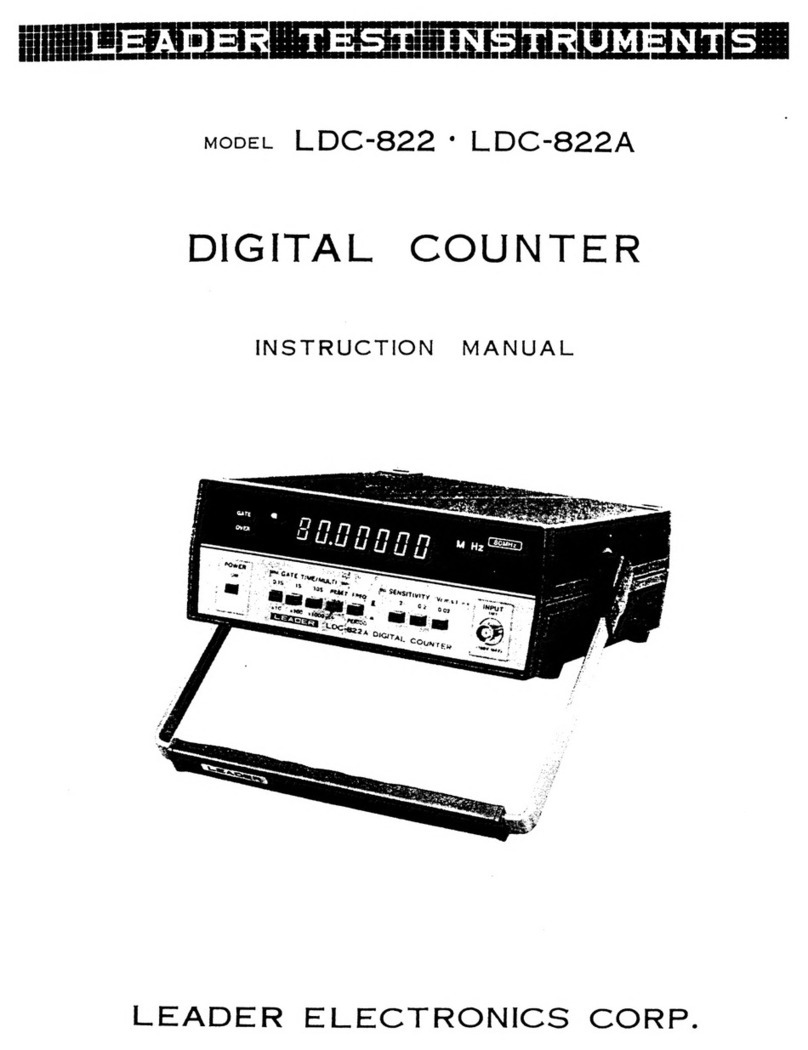
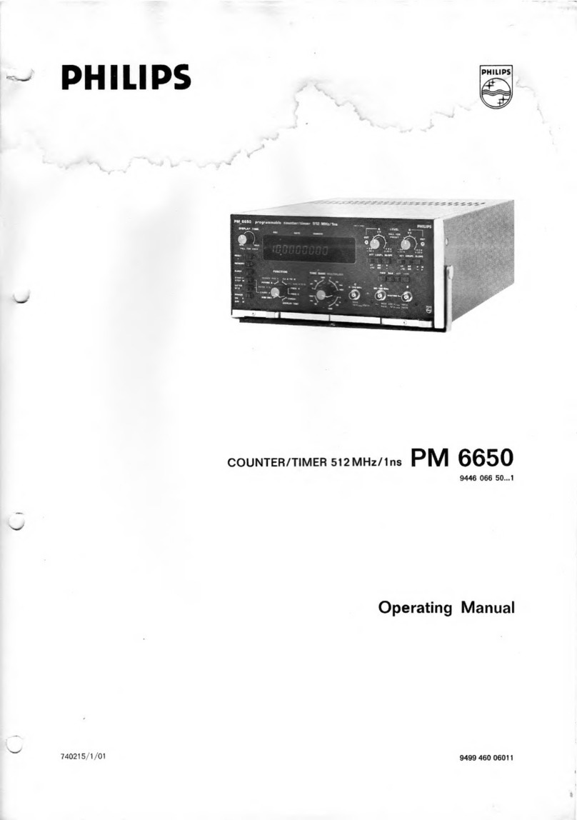
Leader Electronics Corp. LDC-824 User manual


pi
ata
oben
leech
Bis
atts
Tt
ae
a
ee
ee
cog
cap
pbb
ecphusiaet
ics
2
oe
: 2
megan
we
Big
Ga
ck
busted
aks
Deeg
padien
ein
asa
Loewe
neta
Seng
oad
ae
Fe
Lia
EAE
OER
Sethe
Rca
SRE
WSS
Site
gnates
Suey
oy
Fie
Mare
cinsenee
oe
Blog
pi
des
Badin
uedanodtes
Sa
ada
a
en
1.
Introduction
LDC-824°
LDC-824S
DIGITAL
COUNTER
LDC-824(S)
is
a
digital
frequency
counter/timer
designed
to
measure
the
frequency
and
period
of
a
signal,
featuring
a
wide
frequency
range
(10Hz—520MHz),
a
high
input
sensitivity
(20mV
rms),
and
high
resolution
to
8
digits.
The
period
function
makes
the
unit
outstanding
for
video
tape
re-
corder
service
applications.
This
instrument
can
be
used
for
adjustment,
test
and
repair
of
audio
instruments,
AM/FM
radios,
TVs,
CB
radios,
computer
clocks,
amateur-radios,
electronic
watches,
musical
instruments,
etc.
The
LDC-824(S)
is
small
and
portable.
A
big
bright
fluorescent
display
assures
easy
readability
of
values.
The
green
display
does
not
induce
eye
fatigue
even
after
an
extended
period
of
viewing.
Readout
miscounts
are
reduced
by
zero-blanking,
unit-display
(kHz,
MHz,
ms)
and
overrange
display.
The
use
of
LSI
and
MSI
in
the
internal
circuit
assures
reliable
performance
and
less.
power
consumption.
2.
Specifications
Frequency
Measurements
Range
Gate
time
Resolution
Accuracy
Period
Measurements
Range
Multiplication
Factors
Resolution
Accuracy
Input
Section
Input
sensitivity
(MQ)
(502)
Attenuator
Coupling
Input
impedance
Maximum
input
voltage
(1MQ)
(502)
10Hz
—
80MHz
(direct),
50MHz
—
520MHz
(pre-scaler)
0.1s,
1s,
10s
10Hz,
1Hz,
0.1Hz
(direct),
100Hz,
10Hz,
1Hz
(pre-scaler)
+1
count
+
time
base
accuracy
100ms
—
lus
X10,
X100,
X
1000
10pus,
lus,
O.1pus
+1
count
+
time
base
accuracy
+
trigger
error
20m
Vrms
(10Hz
—
80MHz)
50m
Vrms
(80MHz
—
520MHz)
20mVrms
(100kHz
—
80MHz)
50m
Vrms
(80MHz
—
520MHz)
1,
1/10
AC
Switchable
1MQ
and
502.
10Hz
—
400Hz
:
100Vrms
400Hz
—
100kHz
:
20Vrms
100kHz
—
520MHz:
5Vrms
100kHz
—
520MHz:
5Vrms

Time
base
LDC-824(S)
Frequency
Accuracy
Clock
out
External
clock
General
Specifications
Display
Ope
rating
tempe
rature
range
Power
source
Power
consumption
Dimensions
Weight
Accessories
10MHz
(OVEN)
+1x10~%
(tlppm)
(32°F
—
104°F)
(0°C
—
40°C)
Regular
Option
1Vp-p
10MHz
1Vp-p
1MHz
1Vp-p
—
10Vp-p
1Vp-p
—
10Vp-p
8
digits,
7
segment
fluorescent
display
overflow
indication,
gate
indication
and
zero
blanking
0°C
—
40°C
(32°F
—
104°F)
100V,
117V,
200V,
234V
+
10%
50Hz
—
60Hz
(Voltage-change
is
accomplished
by
change
on
tap
of
trans-
former)
Approx.
12VA,
Approx.
18VA
(with
optional)
74(H)
X
200(W)
X
250(D)mm
Approx.
3’(H)
X
8”(W)
X
10°(D)
excluding
knobs
and
legs
Approx.
2.6
kg
Approx.
2.8
kg
(with
optional)
Approx.
5%|bs.
Approx.
6%
lbs.
(with
optional)
Clip
cable
with
BNC
connector

3
3
PANEL
FUNCTIONS
“Ae
Front
Panel
an
(eo)
\
j
(en
et
ea
(S20niie)
&
a
3-1
shows
the
front
panel
of
LDC-824(S).
Power
switch:
To
turn
on,
depress
push-button,
to
turn
off,
again
depress
push
button.
GATE
TIME;
MULTIPLIER
SELECTOR:
For
frequency
measurement,
this
switch
is
used
to
change
GATE
TIME;
when
in
the
_period-measurement
mode,
it
is
used
to
change
the
multiplier
factors.
Each
range
is
as
follows:
GATE
TIME:
0.1,
1
and
10
sec.
MULTL:
xX
10,
X
100
and
X
1000
RESET
Switch:
By
pressing
this
switch,
the
counter
stops
its
operation.
When
released,
the
display
is
cleared
to
zero.
After
a
delay
of
approximately
0.1s,
if
there
is
an
input
signal,
the
counter
starts
counting.
|
Function
Selector:
A
push
button
switch
for
changing
the
measurement
mode
is
used
for
selecting
the
measurement
functions
of
PERIOD
and
FREQ.
|
FREQ.
RANGE
Selector:
Selector
for
DIRECT
MEASUREMENT
(10Hz
—
80MHz)
and
PRE-SCALER
(50MHz
—
520MHz).

(6)
SENSITIVITY
Selector:
Push
button
switch
for
20mV,
200mV,
respectively.
7)
IMPEDANCE
Selector:
Selector
for
input
impedance
of
1MQ
and
50Q.
(g)
INPUT
Connector:
el
Put
a
signal
in
to
measure.
(9)
Handle/Stand
combination:
l
ot
-
pes
youd
The
lock
of
the
handle
can
be
released
by
pressing
the
mounted
part
of
the
handle
on
bo
sides
with
both
hands.
The
handle
can
then
be
freely
rotated.
When
th
is
locked.
QQ
Unit
Indicator:
For
frequency
measurement,
the
indicator
shows
“MHz”
at
520MHz
1
at
80MHz
Freq.
Range.
‘ms’
is
displayed
in
the
case
of
period
measurements.
QD
Display:
It
is
a
8-digit,
7-
-segment,
fluorescent
display.
In
accordance
with
the
measuri:
1g
Tange,
decimal
point
is
displayed
automatically,
and
the
leading
zeros
are
blanked.
G2.
GATE
indicator:
Displays
the
opened
or
closed
state
of
the
GATE.
When
GATE
is
open,
indicator
is
lit.
(3
OVERRANGE
indicator:
:
Lights
when
the
frequency
is
over
the
counting
capacity
of
8
digits.
In
the
case
of
overrange,
push
the
GATE
TIME/MULTI.
selector
to
smaller
values
until
the
overrange
indi-
cator
light
goes
of
f
4
3.2
Rear
Panel:

4.2
©)
SSOE68
Ss)
OUTPUT/INPUT
Terminal:
Output
and
input
terminal
for
a
clock
signal.
When
the
selector-switch
for
internal
and
external
(INT/EXT)
is
on
INT,
the
internal
clock
is
available
to
the
terminal.
Feed
a
clock
to
the
terminal
externally,
when
the
selector
switch
is
on
EXT.
Serial
number
label
Power
cord
Rubber
feet
Fuse
holder
(contains
0.3A
fuse)
INT/EXT
Switch:
Selector
switch
of
an
internal
clock
and
an
external
clock.
With
a
screw
driver,
trimmer
control
adjustments
of
the
reference
frequency
oscillator
can
be
made.
For
procedure,
refer
to
section
6
—
Maintenance.
Operating
Instruction
Precautions
in
use
(1)
(2)
(3)
(4)
(5)
In
connecting
the
instrument
to
the
device
(to
be
tested),
particularly
in
an
internal
connection,
remove
all
AC
power
to
the
device,
and
remove
the
cord.
After
discharging
all
charged
capacitors,
connect
the
cable
for
measurement,
thus,
the
danger
of
an
electrical
shock
can
be
minimized.
Take
the
same
care
in
disconnecting
the
input
cable.
.Use
AC-power
source
of
LDC-824(S)
at
50
—
60Hz,
within
10%
of
rating
voltage.
Caution:
Excessively
large
or
small
AC
voltages
may
induce
erroneous
operation.
In
replacing
the
fuse,
use
the
designated
0.3A
fuse.
Avoid
all
the
severe
mechanical
shocks
to
crystal
oscillator
or
fluorescent
indicators.
Reference
clock:
Wait
about
20
minutes
for
correct
measurement
until
the
crystal
oscil-
lator
gets
stable
in
aging.
Fundamental
Operation
(1)
(2)
(3)
(4)
(5)
(6)
(7)
(8)
Disconnect
the
input
cable
of
the
LDC-824(S).
Connect
the
AC
power
cord
to
the
proper
AC
power
source.
Set
POWER
switch
to
the
ON
position.
Set
the
function
switch
to
FREQ.
Set
the
SENSITIVITY
selector
to
20mVrms.
Put
the
GATE
TIME
Selector
at
0.1S.
When
FREQ.
RANGE
Switch
is
80MHz
and
520MHz,
Display
reads
0.00
kHz
and
0.0000
MHz
respectively.
The
GATE
indication
is
lighted
for
0.1s
while
the
gate
is
open,
and
disappears
for
0.1s
while
the
gate
is
closed.
Set
GATE
TIME
Selector
at
1S.
Display
shows
0.000
kHz
at
80
MHz
and
0.00000
MHz
at
520MHz.
GATE
indicator
re-
peats
to
1s
light
on/0.1s
light
off
alternately.
Press
the
10S
GATE
Selector
Display
shows
0.0000
kHz
at
80
MHz
and
0.000000
MHz
at
520MHz.
GATE
indicator
repeats
to
10s
light
on/0.1s
light
off
alternately.

(9)
Set
the
FUNCTION
switch
to
PERIOD.
(10)
Use
the
“MULTY”’
scales,
and
confirm
the
display
as
shown
in
Table
4-2-1.
In
the
case
that
the
displayed
figure
shows
other
than
0
(zero),
oF
when
GATE
indicator
is
lighted,
push
the
reset
switch,
then,
GATE
indicator
disappears
(gate
is
closed),
and
the
display
shows
as
in
Table
4-2-1.
a
ee
a
ce
DO
Table
4-2-1
(11)
In
the
above
6—10
OVER-flow
indicator
always
shows
light
off.
4.3
Input
Connections
Connect
BNC
Connector
of
the
accessory
cable
to
the
input
terminal.
Connect
the
ground
—
negative
side
of
the
clip
to
the
common
of
the
device
under
test.
Connect
the
positive
hot
side
to
the
test
point.
The
input
is
AC
only
(DC
blocked
by
0.1MF
capacitor).
The
maximum
allowable
voltage
of
the
AC
component
of
the
input
signal
depends
on
frequency.
The
values
are
as
follow:
Input
Impedance
IMQ
10Hz
—
400Hz
100Vrms
or
280V
p-p
400Hz
—
100kHz
20Vrms
or
56Vp-p
50
100kHz
—
520MHz
5Vrms
or
14Vp-p
100kHz
—
520MHz
5Vrms
or
14Vp-p
The
maximum
voltage
of
the
DC
component
of
the
input
signal
is
+
100V
DC.
When
the
input
signal
is
not
a
continuous
sine-wave
or
is
modulated,
the
following
values
are
the
maximum
allowable
AC
input
voltages
permitted
in
accordance
with
the
frequency
chart
below.
Input
Impedance
TMQ
10Hz
—
400Hz
250V
p-p
AQ0Hz
—
100kHz
56Vp-p
500
100kHz
—
520MHz
14Vp-p
100kHz
—
520MHz
14Vp-p
CAUTION
NOTE:
Caution
should
be
taken
not
to
get
an
electric
shock
when
connecting
or
removing
the
input
cable.
High
voltage
circuits
and
horizontal
output
pulses
of
flyback
transformers
in
TV-sets
generate
excessive
voltages.
The
LDC-824(S)
could
be
damaged
by
exceeding
input
limitations.
Therefore,
never
make
a
direct
connection
to
these
circuits.
The
input
impedance
of
this
instrument
is
approx.
1MQ
and
shunted
by
approximately
30pF.
The
input
cable
has
a
distributed
capacity
of
approx.
7OpF.
As
the
capacitance
becomes
100p
F
in
total,
it
is
not
recommended
for
such
a
circuit
or
a
device
under
test
as
influenced
by
this
capacitance
to
be
measured.
:
Note:
Do
not
connect
the
input
of
LDC-824(S)
to
a
high
impedance
point
of
the
device
under
test.
The
parallel
effects
of
this
1M2/100pF
combination
affect
the
operation
of
the
circuit
being
tested.

4.4
Setting
of
input
sensitivity
(1)
Input
sensitivity
and
noise
The
input
sensitivity
of
LDC-824(S)
can
be
selected
from
0.02Vrms,
or
0.2Vrms,
in
order
to
measure
input
signals
of
wide
voltage
ranges.
When
a
large
signal
is
applied
to
the
input
at
the
higher
input
sensitivity,
the
noise
included
in
the
input
signal
may
induce
miscounting.
In
this
case,
reduce
the
input
sensitivity
to
the
appropriate
input
range
as
listed
in
Table
4-4-1.
This
minimizes
errors.
0.02Vrms
0.02
—
0.2Vrms
0.2
—
2Vrms
Table
4-4-1
Automatic
Trigger
Level
Function
The
trigger
level
of
LDC-824(S)
is
designed
to
function
automatically
in
80MHz
frequency
range.
|
Trigger
level
is
set
automatically
to
a
level
(Fig.
4-4-2)
of
input
voltage
that
is
divided
equally
into
three
parts.
The
functional
range
of
automatic
trigger
level
shall
be,
for
instance,
between
20mV
and
200mV
input
voltage
when
preset
sensitivity
is
20mV.
When
it
is
preset
at
200mV,
the
input
voltage
range
for
automatic
trigger
level
is
between
200mV
and
2V.
In
the
case
the
above-mentioned
input
voltage
range
is
exceeded,
the
trigger
level
is
fixed
at
200mV
position
when
preset
at
20mV
sensitivity
and
is
fixed
at
2V
position
when
preset
at
200mV
sensitivity.
In
accordance
with
all
these,
correct
signal
counting
can
be
conducted
(Fig.
4-4-2)
without
miscounting
when
noise
voltage
is
50%
or
less
of
the
signal
voltage
and
it
is
within
the
range
of
automatic
trigger
level.
In
addition,
measurement
of
pulse
signals
with
large
duty
ratio
can
be
conducted
with
ease,
as
the
trigger
level
is
set
automatically
at
the
optimum
level,
even
if
it
has
been
necessary
to
adjust
the
trigger
level
for
the
pulse
signal
measurement.
Positive
Peak
Noise
Upper
Trigger
Level
Lower
Trigger
Level
Input
Signal
Negative
Peak
Shaped
Signal
FLL.
Fig.
4-4-2

(3)
|
Measurements
of
Modulated
Signals
{lye
nell
Ds
UT
de
|
al
i
al
Ve
VH:
Input
Sensitivity
of
counter
As
seen
in
the
above
Fig.
4-4-3,
in
order
to
measure
the
frequency
of
modulated
Modulated
signal
carrier-wave,
if
the
voltage
of
highest
modulated
part
is
greater
than
the
input
sensitivity
VH
(0.02Vrms),
it is
then
possible
to
count
the
carrier-wave.
4.5
Frequency
measurement
Set
the
function
switch
to
FREQ.
and apply
signal
to
the
input
connector.
The
measuring
range
is
10Hz
—
520MHz.
By
setting
the
GATE
time
to
the
values
shown
in
Table
4-5-1
and
Table
4-5-2,
measurement
can
be
done
at
the
maximum
resolution
without
overrange.
DIRECT
MEASUREMENT
(up
to
80
MHz)
Gate
Time
Measuring
frequency
Display
10
S
10Hz
—
9999.9999kHz
|
0.0100kHz
—
9999.9999kHz
1S
10Hz
—
80000.000kHz
|
0.010kHz
—
80000.000kHz
0.1S
10Hz
—
80000.00kHz
0.01kHz
—
80000.00kHz
Table
4-5-1
PRE-SCALER
(up
to
520
MHz)
Gate
Time
Measuring
frequency
Display
10
S
10Hz
—
99.999999MHz
|
0.000010MHz
—
99.999999MHz
1S
0.00001MHz
—
520.00000MHz
0s
Table
4-5-2
In
measuring
the
frequency
of
10Hz
—
1kHz
at
a
high
resolution,
period-measurement
is
more
suitable.
4.6
Period
measurement
(1)
Set
the
function
switch
to
PERIOD,
and
apply
the
signal
to
the
input
connector.
The
measuring
range
is
100ms
—
0.001ms
(1us).
Period
measurement
is
suitable
for
accurate
measurement
in
the
frequency
range
of
10Hz
—
1kHz.
By
setting
the
MULTI.
and
PERIOD
as
listed
in
Tables
4-6-1
and
4-6-2,
more
accurate

measurements
can
be
accomplished
within
a
short
time
and
longer
numerical
display
measurement
results
in
a
more
accurate
measurement.
When
the
measuring
time
is
within
1s
—
0.1s,
1ms
—
0.1ms
1.0000ms
—
0.1000ms
Table
4-6-1
When
the
measuring
time
is
within
10s
—
1s,
Dipl
10Hz
—
100Hz
100ms
—
10ms
X100
100.000ms
—
10.000ms
100Hz
—
1kHz
X1000
10.0000ms
—
1.0000ms
Table
4-6-2
(2)
|
Measuring
accuracy
The
accuracy
of
period
measurement
can
be
expressed
as
follows:
Accuracy
=
+1
count
+
trigger
error
+
time
base
accuracy
.
.
.
Equation
4-6-1.
‘
In
the
above
equation,
the
most
important
factor
is
the
trigger-error.
Trigger-error
occurs
with
the
overlapped
signal
noise
and
noise
in
the
counter.
During
the
measurement,
when
the
display
fluctuating
range
is
within
+1,
the
error
can
be
regarded
as
+1
count.
If
it
is
over
+1
count,
it
may
be
trigger-error
or
alteration
of
the
input
signal.
As
a
checking
method,
when
the
input
sensitivity
of
counter
or
input
voltage
is
set
to
higher
values,
if
the
variable
range
becomes
less,
it
can
be
judged
as
trigger
error.
In
order
to
reduce
the
effect
of-input
signal
noise
the
trigger-error
can
be
reduced
by
:
raising
the
input
voltage
or
by
rectifying
the
input-wave
into
rectangular
wave-form
applying
to
LDC-824(S).
By

ees
ome
yO)
SDINOYLO
3173
Y¥30VI1
DILVWSHIS
9$0
Wix
ZHWOL
9SO0
WW1LXx
ZHW
HOLIMS
Yu3M0d
yv
O00
Y3MOd
ZHWOL
Jdgkt
NOSIO3Ud
HOI
NO!li1d0
3dAd
YVINOSY
A0Op—
AS-
AS+
ZHWI
aQ3aivino3”
Ol
on
OOOLX
Ol
Ot
ZHHOL
\
ZHAOOL
L
Sot
ws
Sl
A
ee
ae
e
%
e
LNANI
Alngine
8
3NVd
Yyy3-
@
adi”
HyO10373S
3SVa
3aWil
3d
‘
4y3aTIONLNOD
shits
avILN3NO3S
13S
3d
3
13934
0
ZHWO00S
oA
—
<
ZHWO0O0S
ZHWOOS~ZHWOS
—
a
eae
ae
Onn
yaiwosaud
UaldITd
WY
:
3
ZHWOS
3s
at
i
5
AONS
a
z
+
LNIOd
AwWI9D30
LINN
MO
14
43A0
LIOID
8
SadavHS
rvds
HAL
+©)
:
4314ITGWY
YyOLVNN]
Liv
LNgNi
Vv
it
@)
Av1dSt3
LNSOS3Y¥ONTS
V3aNvd
LNCHS
Wi¥OVIG
NOCTa
ASLNNOD
AW
LIid
sv2s-
201
—
10
—

te
CA
Pe
an
mean
tare
mento
ene
oy
ER
RRP
RT
SULA
LTD
ene
ieee
feat
kd
2a
wae
boy
a
ia
eC
y
te
Yeah
e
&
é,
«
bt
Sort
Dae
Sipe
ES
Akt
te
atte
Na
te
ee
ae
Sey
AES
Sie
ance
nests
a
Acie,
eM
aD
mete
Se
6.
MAINTENANCE
(1)
To
calibrate
or
adjust
the
reference
oscillator.
Set
GATE
TIME
selector
to
10s
and
FREQ.
RANGE
selector
to
80
MHz.
A
standard
10MHz
signal
generator
with
an
accuracy
greater
than
+1
X
107°
is
required
for
calibration.
Apply
the
output
of
standard
signal
generator
to
the
input
terminal
of
LDC-824
(S)
to
measure
the
frequency.
A
normally
operating
counter
displays
10MHz.
If
you
read
other
than
1OMHz,
adjust
the
trimmer
capacitor
with
the
screw
driver
through
the
hole
for
adjustment
provided
at
the
rear
panel
of
the
LDC-824(S),
in
order
to
make
exact
accurate
display.
(2)
The
LDC-824(S)
has
been
designed
for
easy
maintenance
and
high
reliability
by
employing
(3)
LSI/MSI
IC’s
for
the
digital
and
power-source
sections
of
this
instrument.
If
the
instrument
fails
to
perform
in
the
manner
specified
herein,
write
or
call
your
nearest
Leader
office
for
factory-trained
service.
For
safety
reasons,
and
to
prevent
damage
to
the
instrument,
DO
NOT
REMOVE
the
unit
from
the
case.

Y9LwIS)
Aavddsis
sveg
-
907
lapow
JILVABHSS
gq
2
gl
9!
iut3
T3A
SSA
OOA
6
oe)
goty
re
Ge
ey
aT
|
[1
£95
7€
2140
uN
ZOSV7L
ore
S01!
e9Sist
101d
en
QO
ZUIS7L
woud
48
y[V70191
T
abt}
rt
|
oid
“7
0Ir
v
(
)
0-2L€9S2
nto
an
en
eT
ie
“f/
t0ld
‘
apne,
is
a
ly?
<Y
ZSty]
Isis
9-9Z2évSZ
£018
100
100
vOld
|
E019
3™00
Sold
LA

"dvO2
SOINOULI3I3
YsavaT]
PIWISHEG
ay
=
Va)
EttlL-oO
Woe.
00
1
|apOW.
JILVW3HOS
OcLy
BoQe2
2H
Hoe
Ux
ey
5]
dt;
eu}
pl
Si2iosz
$?B
("
XS
SOLE
Sas,
p
Qts22
Ley
98u
vey
4d§
SED
3m
6
00
€9
ido
ai
£23
OLp
sare?
‘d¥OD
SOINOYLI3IN3
¥30V31
Nn
tanarat
Nd
we
tat
Ae
AzZ\—
wr
TT
0900
oe
LUNId
LENtd
$9I
WOUS
vol
Y3QIArIG
S
V'0
an
06S
pL
WON
S
LLNId
I
yaar
ZHOOL
9IIWOUS
SI
0
0.0
pe
YSCLAIG
fos
1p
It
NId
O6S1bL
ot
GAs
LoWoys
jAS=-o
st
yxXLy
SOL
e
964
loan
a
a
Dee
Ps
92L¥S
0
OO
so
gS
EL
Lome
ve
ant
dex
oo
AS—=-O
100
9
6
Vv
Ol
Ga
ONLY
6}
a
PY
°0e.Q
Pe
13$34
Ned
od
es
139ay
ONL
6u
v|
¥6
291
O6S7¥L
WOYS
410°
evo
v
ai
er
hy
AS=O
0
0
A
aos]
Says
ema
es
vip
4
ZHNO
©.O7zH
aay
BS
WO8
OO
AS
)
L
OLY
A2l—
1001
3
ky
|
LAGNI
oly
a
Vad
5001
ae
“|
of
tte
ia
ss
5001
swt
“EL
_<
ano
B22
ool
00l
(Me
Lore
Siu
2ty
ity
|
OWL
—
|
awoz
3dS
i
SiSh
i
B8SISI
ees!
91SSI
OW
bt
ea
aK
id
ole
(=>
it,
rave
"7
x8022
Sge
ds
a
“st
|
ImLO
€)

‘dy02
SOINOH10373
y30V3)
YP
CV
OMLy
aE:
lo
sof
iezar
4
am
5001
|,NO3
=F
9000
4S
LOKG
Z
¢
ASZ
14
42
AS2
>
ANZ
4
gol
o1v9
=
Sov?
vy
odin
ra
g0r)
Agi~
ea
Raa
10;
90)
3d001
2
Zi
6k
ft
19701
'SOvQ
rp
S$
Ot
€
awnois
S|
>.
920
@
-31v9
2
10
4
ZHO0t
:
(<0)
Ze)
19201
O
{)
ad
‘
4018
:
nif
Sy
6
1970
we
org
"
a
ZHOL
Ase
110
{I
L0vd
20¥d{
zowr
rove
0
S
bE
Ye
\
uy
LS
O—O
1X3
ough
(1)
i
O
sl
ane
<4
4
sgzat
w8ZGl
=
ygz0t
90s0
$0sd
10$0
|
LNOILdO
s¢ze
-
907
‘2NOILdO.
eI
Y
en
RT
ET
ee
This manual suits for next models
1
Table of contents
Other Leader Electronics Corp. Cash Counter manuals
