Leader Electronics Corp. LPS-160A User manual

'1111111.•1···1-~l··"·······"•lliiJ·····!··I··illl
•.
i··~~il··"·····"~~~·~:.;··~·ll
l
'· I
·
-~
,.
····
·-~
~·
-
·
"d.. ..
..
I'
I ·'
·-
. ·
-·
~
11
1
..
,.
"''
~
·
·-
•
laal
~
! I
••
.t
lilt.
"CI
I 1
•
••
1
~~
lilt.'
~
..
..
"C
I i '
;a
I ' 11
110
l •••••••
•••
........
••• •• .... • •
Iii
'
•••
••
•
•••
•
..
MODEL
LPS-160A/t
61
A/
162A
/t
63A/t
64A
REGULATED
DC
POWER
SUPPLY
32V
SERIES
INSTRUCTION
MANUAL
LEADER
ELECTRONICS
CORP.

CONTENTS
PAGE
1.
INTRODUCTION..............................
2
2.
FEATURES . . . . . . . . . . . . . . . . . . . . . . . . . . . . . . . . . 2
3.
SPECIFICATIONS . . . . . . . . . . . . . . . . . . . . . . . . . . . . . 3
4. DESCRIPTION
OF
PANEL FUNCTIONS . . . . . . . . . . . . . 5
4.1 Front Panel . . . . . . . . . . . . . . . . . . . . . . . . . . . . . . . 5
4.2 Rear Panel . . . . . . . . . . . . . . . . . . . . . . . . . . . . . . . . 7
5.
NOTES
ON
OPERATION . . . . . . . . . . . . . . . . . . . . . . . . 9
6.
OPERATIONS
................................
11
6.1
Independent Operation . . . . . . . . . . . . . . . . . . . . . . .
11
6.2 Series Operation . . . . . . . . . . . . . . . . . . . . . . . . . . . . 12
6.3 Parallel Connection . . . . . . . . . . . . . . . . . . . . . . . . . . 14
7.
NOTES
ON
ENVIRONMENTAL CONDITION
..........
16
8.
· CURRENT LIMITING CIRCUIT
......................
16
9. CIRCUIT DIAGRAMS
..........................
17
1. INTRODUCTION
LPS-160A
to
164A, 32V series are regulated
DC
power supply
units with voltmeter and amperemeter; the LPS-160A can supply
the
DC
power
of
0
to
32V, 0.5A; the
LPS-161
A 0
to
32V, 1.2A; the
LPS-
162A 0
to
32V, 2A; the LPS-163A 0
to
32V, 3A; and the LPS-164A 0
to
32V, 5A. They are provided with continuously variable coarse ad-
justment and fine adjustment
of
the
output
voltages, and with continu-
ously variable current adjustment
in
a range of 10
to
100%.
2.
FEATURES
o Built-in
output
current limiter circuit.
o Availability of series and/or parallel operation.
-2-

3. SPECIFICATIONS
MODEL
LPS-160A LPS-161A
Output
voltage
0-
32 V Continuously variable
Output
polarity Positive
and
negative
Output
current
o-
o.5A
o-1.2A
Ripple voltage
Less
than 3mVp-p
Output
stability
Less
than 5mV
for
power source voltage
change
of±
10%
Less
than 5mV
for
load variation
of
0
to
100%
Voltmeter
40V
(F.S)
Accuracy
of
2.5%
for
full
scale
Amperemeter,
0.6A
(F.S)
1.5A
(F.S)
Accuracy
of
2.5% Accuracy
of
2.5%
for
full
scale
for
full
scale
Insulation Between
chassis
and
output
terminal:
More than 10
MQ
at
DC 500V
Between
chassis
and
AC
plug:
More than 50MQ at DC 500V
Compensation/ Overload protection circuit
of
constant current
protection
circuit
self-restoring type
Ambient
tempe-
0-
+40°C
rijture
range
;·Power Source
AC
100-
120V AC
100-
120V
-50/60Hz 4
7V
A 50/60Hz 84
VA
..
AC
200-
240V ·
AC 200 -240V
50/60Hz 24
VA
50/60Hz
43V
A
Size
and weight 175(H) x 100(W) x 195(D)mm 3.5
kg
Accessories _ Short-circuit bar x 1
Fuse
x1
Operation
Series
and parallel
-3-
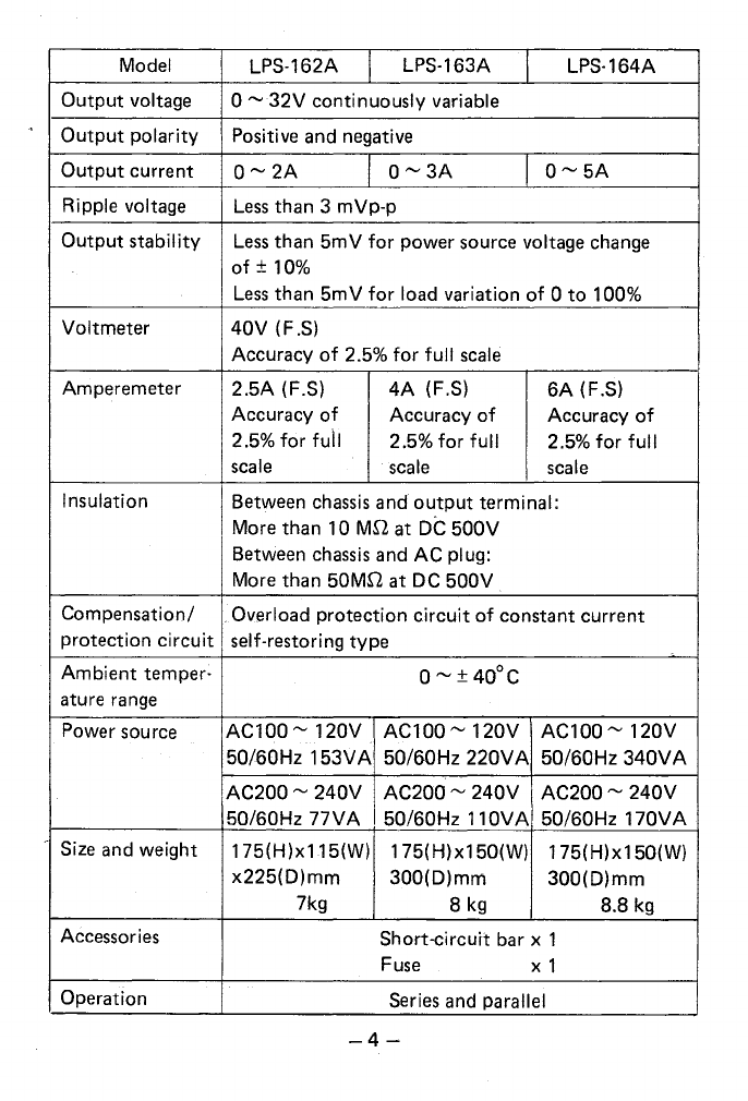
Model LPS-162A LPS-163A LPS-164A
Output
voltage
0-
32V
continuously variable
Output
polarity
Positive and negative
Output
current
0-2A
o-3A
0-5A
Ripple voltage
Less
than 3 mVp-p
Output
stability
Less
than
5mV
for
power source voltage change
of±
10%
Less
than
5mV
for
load variation
of
0
to
100%
Voltmeter
40V
(F.S)
Accuracy
of
2.5%
for
full
scale
Amperemeter
2.5A
(F.S)
4A
(F.S)
6A
(F.S)
Accuracy
of
Accuracy
of
Accuracy
of
2.5%
for
fuil
2.5%
for
full
2.5%
for
full
scale
scale
scale
Insulation Between
chassis
and
output
terminal:
More than 10
MD
at
DC
500V
Between
chassis
and
AC
plug:
More than 50M.Q at DC
500V
Compensation/ .Overload protection
circuit
of
constant current
protection
circuit
self-restoring
type
Ambient
temper: 0
-±
40°C
ature
range
Power source
AC100-120V
AC100-
120V
AC100-
120V
50/60Hz
153V
A 50/60Hz
220V
A 50/60Hz
340V
A
AC200~
240V
AC200-
240V
AC200~
240V
50/60Hz
77VA
50/60Hz
11
OVA 50/60Hz
170V
A
· Size and weight 175(H)x115(W) 175(H)x150(W) 175(H)x150(W)
x225(D)mm
300(D)mm
300(D)mm
7kg 8
kg
8.8
kg
Accessories Short-circuit bar x 1
Fuse
X 1
Operation
Series
and parallel
-4-
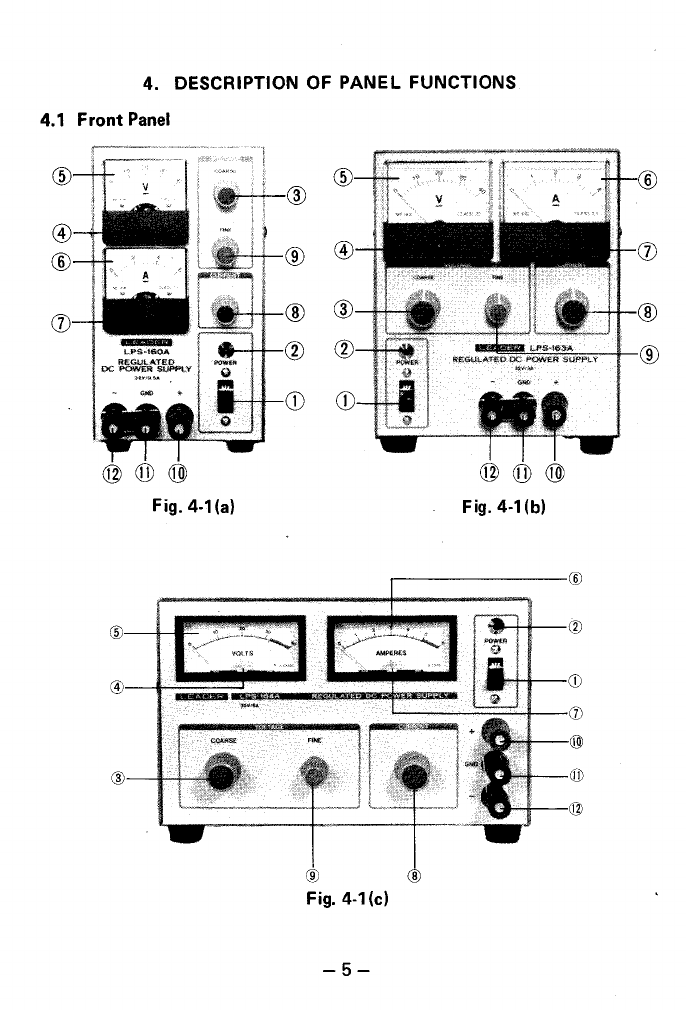
4. DESCRIPTION OF PANEL FUNCTIONS
4.1
Front
Panel
Fig.
4·1
(a) Fig.
4-1
(b)
Fig. 4-1(c)
-5-

CD
Power switch:
Turns on and
off
the
power.
(])
Pilot lamp:
Indicates
the
power-on condition when it
is
on.
@COARSE:
Is
the
coarse
adjustment
knob
of
the
output
voltage.
@)
Zero adjuster:
Is
the
mechanical zero adjuster screw for
the
voltmeter.
If
the
meter needle
is
off
the
zero position, adjust
the
screw
while
the
power
is
off.
@ Voltage indicator:
Set
an
output
voltage while reading
the
voltage indication.
® Load
current
indicator:
Indicates
the
load
current.
(J)
Zero adjuster:
Is
the
mechanical zero adjuster screw
for
the
amperemeter.
If
the
meter needle
is
off
the
zero position when
the
power
is
off
or
with no load, adjust
the
screw by a screw driver.
@CURRENT:
Is
the
current
limiting knob for setting and adjusting
the
output
current
in
a range
of
max. 10
to
100%.
@FINE:
Is
the
fine
adjustment
knob
of
the
output
voltage.
@
+:
Is
the
positive side
of
output
terminal.
-6-
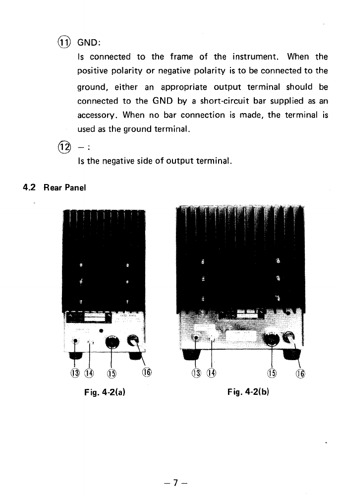
@ GND:
Is
connected
to
the frame
of
the instrument.
When
the
positive
polarity
or
negative
polarity
is
to
be
connected
to
the
ground, either
an
appropriate
output
terminal should
be
connected
to
the
GND
by a short-circuit bar supplied
as
an
accessory.
When
no bar connection
is
made, the terminal
is
used
as
the ground terminal.
Is
the negative side
of
output
terminal.
4.2
Rear
Panel
•
~r
'~
@(j])
@ @
Fig. 4-2(a) Fig. 4-2(b)
-7-

Fig.
4-2(c)
@
P:
Is
the
connection
terminal for
the
parallel
operation.
(See
the
description for
the
details.)
@
G:
Is
the
ground terminal,
@ Fuse:
Turn
the
cap
counterclockwise
to
remove
the
fuse.
@
AC
power
cord
-8-

5.
NOTES ON OPERATION
(1)
Apply
the
specified voltage
to
the
primary
input
side.
(2) When a low voltage
is
used near
the
maximum
current,
be
sure
to
provide a
enough
ventilation
area near
the
radiator.
(See Fig. 5-1)
RADIATOR
Fig. 5-1 (a) Fig. 5-1(b)
Fig.
5-1
(c)
-9-
(3) Before using a parallel operation,
read
the instruction carefully.
(4)
When
using the instrument
as
a power supply
for
a high frequency
device, connect the GND terminal
to
the ground. The frame will
play a roll
of
the shield between the power supply
and
the
amplifier.
(5)
Even
when the
output
is
overloaded
or
short-circuited, the
output
current limiting circuit
is
activated. The short-circuit current flows
in a
range
of
10
to
100%
of
the maximum current. For example,
when the current setting knob
is
turned
full
counterclockwise,
the current in a
range
of
100
to
500
mA
flows, and the ampere-
meter indicates the current. This current
flow
occurs
regardless
the setting current.
When
a load
to
be
tested
is
a type
of
load
that
can
be
broken by the current, a
care
must be taken
for
use
of
the
instrument.
-10-
6. OPERATIONS
6.1 Independent Operation
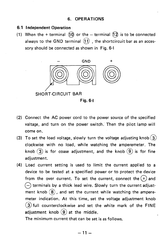
(
1)
When
the
+ terminal @ or
the
-terminal
@
is
to
be connected
always
to
the
GND terminal
GJ)
,
the
shortcircuit bar
as
an acces·
sory should be connected
as
shown
in
Fig.
6·1
GND
+
SHORT-CIRCUIT
BAR
Fig.
6-1
(2) Connect
the
AC
power cord
to
the
power source
of
the
specified
valtage, and
turn
on
the
power switch. Then
the
pilot lamp will
come
on.
(3)
To
set
the
load voltage, slowly
turn
the voltage adjusting
knob@
clockwise with no load, while watching
the
amperemeter. The
knob
@
is
for coase adjustment, and
the
knob
@
is
for fine
adjustment.
(4)
Load
current
setting
is
used
to
limit
the
current applied
to
a
device
to
be tested at a specified power
or
to
protect
the
device
from
the
over current.
To
set
the
current,
connect
the
G)
and
8 terminals by a thick lead wire. Slowly
turn
the
current
adjust-
ment
knob
@,
and set
the
current
while watching
the
ampere-
meter indication.
At
this time, set
the
voltage adjustment knob
@full
counterclockwise and set
the
white mark of
the
FINE
adjustment knob
@at
the
middle.
The minimum
current
that
can be set
is
as
follows.
-11-
LPS-160A
Approx.
20m
A
LPS-161A
Approx.
50mA
LPS-162A
Approx.
100mA
LPS-163A
Approx.
200mA
LPS-164A
Approx.
500mA
After
setting
a limiting
current,
remove
the
short-circuit
wire.
Then
set
the
voltage
to
a required level.
(5)
After
completing
the
above
procedure,
watch
the
polarity
of
a
device
to
be applied
and
use
the
instrument.
If
the
voltmeter
indication becomes less
than
the
set
level for a
defect
of
a device
to
be
tested
or
for
any
other
reason,
the
overcurrent
protection
circuit
is
activated, resulting in switching
into
the
constant
current
operation
from
the
constant
voltage
operation.
When
the
instrument
is
to
be used in
the
constant
voltage
operat-
ing
condition,
set
the
current
adjustment
knob
full clockwise.
In
this
case
the
short-circuit
current
is
0.5A
+10%
for
the
LPS-160A,
1.2A
+1
0%
for
the
LPS-161 A,
2A
+1
0%
for
the
LPS-
162A,
3A
+1
0%
for
the
LPS-163A, and
5A
+1
0%
for
the
LPS-
164A.
6.2
Series
Operation
(
1)
By
connecting
a
couple
of
the
units in series, a higher voltage
than
a single
unit
is
available.
In
such a case,
no
terminal
should
be
applied
with
a voltage
more
than
the
rating voltage against
the
ground
potential
between
a terminal
and
the
panel/chassis.
The
rating voltage against
the
ground
is
±1
00
V.
With a series
operation
of
a
couple
of
the
units, a
double
of
the
rating voltage
of
a single
unit
and
a
capacity
of
the
current
-12-
of
a single unit are available.
When
two
units are used,
the
maximum voltage available
is
+64V
or-64
V.
The current available
is
0.5A for LPS-160A, 1.2A for
LPS-161A, 2A for LPS-162A,
3A
for LPS-163A and
5A
for
LPS-
164A.
Note: The overcurrent protection
is
effective
at
the smaller value
set
of
the two.
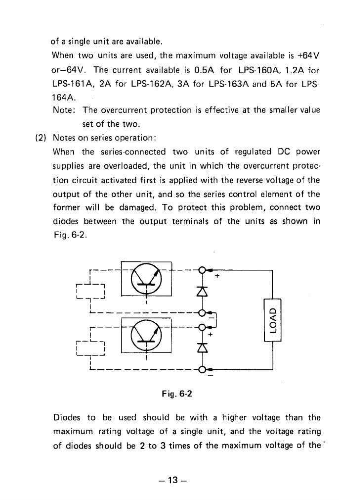
(2)
Notes on series operation:
When the series-connected two units
of
regulated
DC
power
supplies are overloaded, the unit
in
which the overcurrent protec-
tion circuit activated first
is
applied with
the
reverse voltage
of
the
output
of
the
other
unit, and so
the
series control element
of
the
former
will
be
damaged.
To
protect this problem, connect two
diodes between the
output
terminals
of
the units
as
shown
in
Fig. 6-2.
,L~--fi\)il--
l......,-..J~
I I
&....-----------
Fig. 6-2
Diodes
to
be used should
be
with a higher voltage than the
maximum rating voltage
of
a single unit, and
the
voltage rating
of
diodes should be 2
to
3 times
of
the
maximum voltage
of
the
·
-13-
series
connection.
For
example,
use
Toshiba's 3BZ61 (or the
equivalent)
or
151380 ·G2Bs in parallel connection.
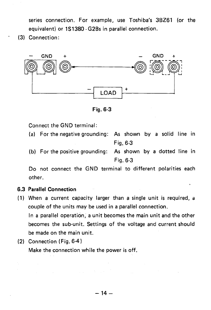
(3) Connection:
GND + GND +
~------~~~-~!
._..
'--....
L...l
+
Fig. 6-3
Connect the GND terminal:
(a)
For
the negative grounding:
As
shown
by
a solid line in
Fig, 6-3
(b)
For
the positive grounding:
As
shown
by
a
dotted
line in
Fig. 6-3
Do
not
connect the GND terminal
to
different
polarities
each
other.
6.3 Parallel Connection
(
1)
When
a current capacity larger than a single
unit
is
required, a
couple
of
the units may
be
used
in a parallel connection.
In a parallel operation, a
unit
becomes the main
unit
and the other
becomes the sub-unit. Settings
of
the voltage and current should
be
made on the main
unit.
(2) Connection (Fig. 6-4)
Make the connection while the power
is
off.
-14-

(a)
Connection on the
front
panel:
GND
+
GND
+
~
(SUB)
(b) Connection
on
the
rear
panel:
PARALLEL
PARALLEL
@~----------@
REAR PANEL OF REAR PANEL OF THE
THE
MAIN
UNIT
SUB-UNIT
Fig.
6-4
For parallel operation-,
make
the connection
in
the
sequence
of
the
0 terminal
of
the main
unit,
G)
terminal
of
the sub-unit; 8
terminal
of
the main
unit,
and
8 terminal
of
the sub-unit. Then
connect the wires between the
PARALLEL
terminal (main unit)
and
the
PARALLEL
terminal (sub-unit).
Use
thick wires
for
all
the connections.
(a)
Turn the voltage knobs
@,@and
the current knob
@of
the sub-unit full clockwise.
(b) The voltage
and
the current
are
variable by the
mai"n
unit.
The output current
limit
can
be
selected within a
range
of
about 10
to
100%
of
the double
of
the maximum rating
current.
In this
case,
as
the load current
increases,
the amperemeters
of
both the main
and
slave
units swing,
and
the load current
is
-15-

indicated
as
the
sum
of
both
amperemeters.
Notes: Other types
of
regulated
DC
power supply can
not
be
connected for parallel operation. The maximum
number
of
units for parallel operation
is
2 units.
7. NOTES
ON
ENVIRONMENTAL CONDITION
7.1 Avoid
to
use
the
unit
in
such a place where
the
ambient tempe-
rature exceeds
40°C
or
under
the
direct sun shines. Limit
the
maximum
output
current,
when
the
unit
is
used
in
such a place
where ventilation
is
interrupted
or
where a radiation exists from
other
equipments.
7.2
Use
the
instrument within ±10% of
the
specified voltage
of
the
power source.
8.
CURRENT LIMITING CIRCUIT
When
the
output
terminals are short-circuited by mistake,
the
current
limiting circuit
is
activated
to
limit
the
flow
of
the
current
in excess
of
the
rating
output
current,
so
that
the
control elements and
the
amperemeter connected
in
series
in
the
instrument are protected from
the sudden damage.
The
output
limit
current
can be set
in
a range
of
10
to
100%
of
the
rating
current,
and when the
output
current
reaches
the
set value,
the
instrument operates
in
the
constant
current
condition.
As
the
output
current
comes down below the set value,
the
constant
voltage condition
is
automatically resumed.
-16-
......
I
roov
ov
J20V
IOOV
OV
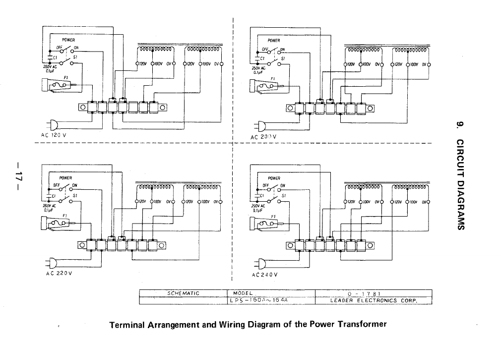
AC
120 V
I
I
I
I
I
I
I
I
AC
20JV
120V
IOOV
OV
!20V
IOOV
OV
---------------------------------~~---------------------------------
AC
22
OV
120V
IOOV
OV
1
I
I
I
I
I
I
I
I
I
I
I
I
I
I
I
I
I
I
I
I
I
I
l20V
roov
ov
AC240V
f--,--'S::C:::_H_::E:::_M~Ac:T~I:e_C
___
-+c-M::;::O':D.".E
L
....
_____
-~-~-
_L§~Ic:cc=:c-:cc:-::-::---i
L_
__________
_L;:L.::_P_;Sc_-_:.1_::6_::0~''_.;-((34A---
LEADER
ELECTRONICS
CORP.
Terminal Arrangement and Wiring Diagram
of
the Power Transformer
("')
:::0
("')
c:
-1
0
5>
C>
:::0
)>
s:
(I)
CXl
I
ZOJ
RDll.2fBI
'
"
~
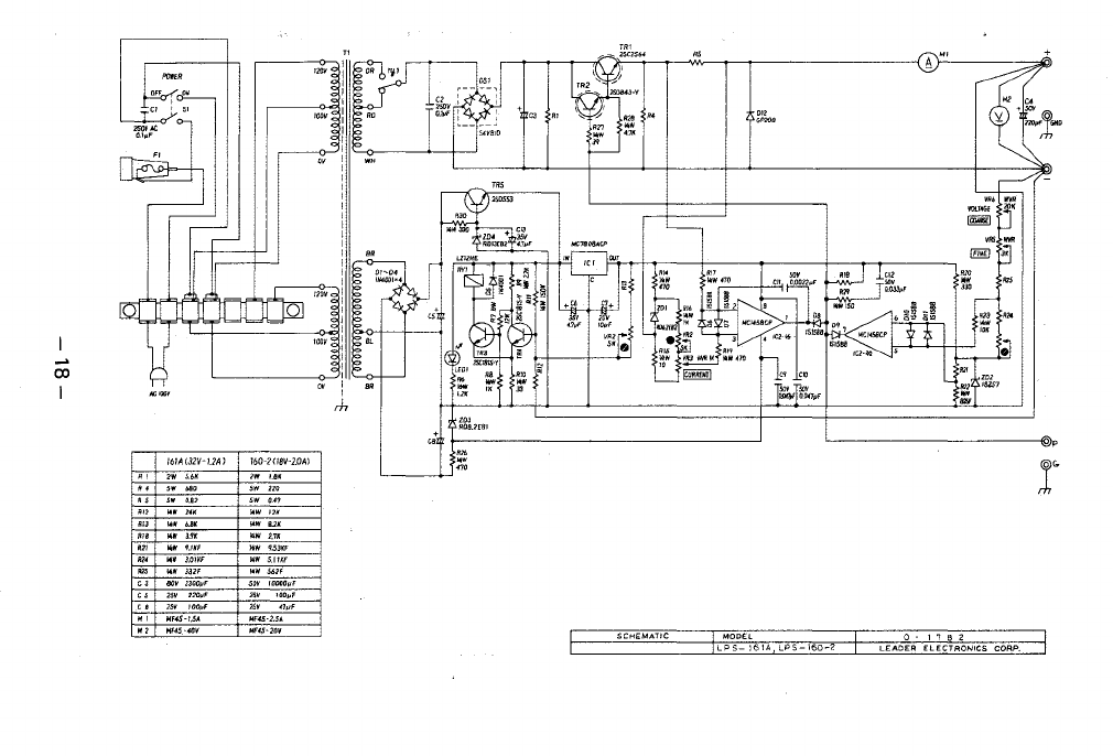
161A(32V-1.2A)
l60-2H8V-2.0AJ
..
""
" ,.
UIK
"
,.
""
'"
..
....
'"
..
3.'fK
..
2,7K
"'
..
3.01KF
..
S.IJKF
"'
..
332F
~jjW
S62F.
C3
80V3300pF
...
F000011F
"'
J00jlf
" '"
/OOJJF
"'
47JJF
"
HF4S-1.5A
lofF45-2.SA
Hf.j5>.f0V
SCHEMATIC
MODEL
0 - 1 7 8 2
LPS
161A
LPS
160-2
LEADER
ELECTRONICS
CORP.
co
I
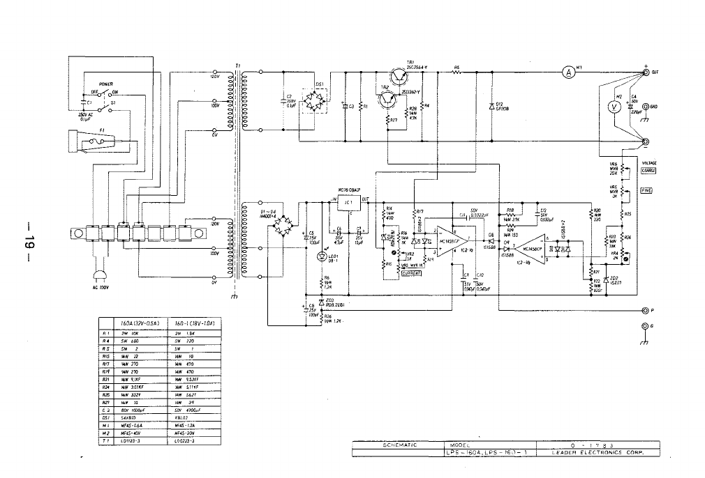
!60AC32V-0.5A)
SW
680
80VJOOCpF
S4VB!D
160-1(18V-10A)
5DV
4700pF
""
+ ;gV RDBl£61
IOOuF
R26
Y.IW
1.2K
'--------------"
SCHEMATIC
MODEl
0 - 1 7 8 3
LPS
160A,
LPS
16J
1
LEADER
ElECTRONICS
CORP.
This manual suits for next models
4
Table of contents
Popular Power Supply manuals by other brands

Videx
Videx 520MR Installation instruction

Poppstar
Poppstar 1008821 Instructions for use

TDK-Lambda
TDK-Lambda LZS-A1000-3 Installation, operation and maintenance manual

TDK-Lambda
TDK-Lambda 500A instruction manual

Calira
Calira EVS 17/07-DS/IU operating instructions

Monacor
Monacor PS-12CCD instruction manual


