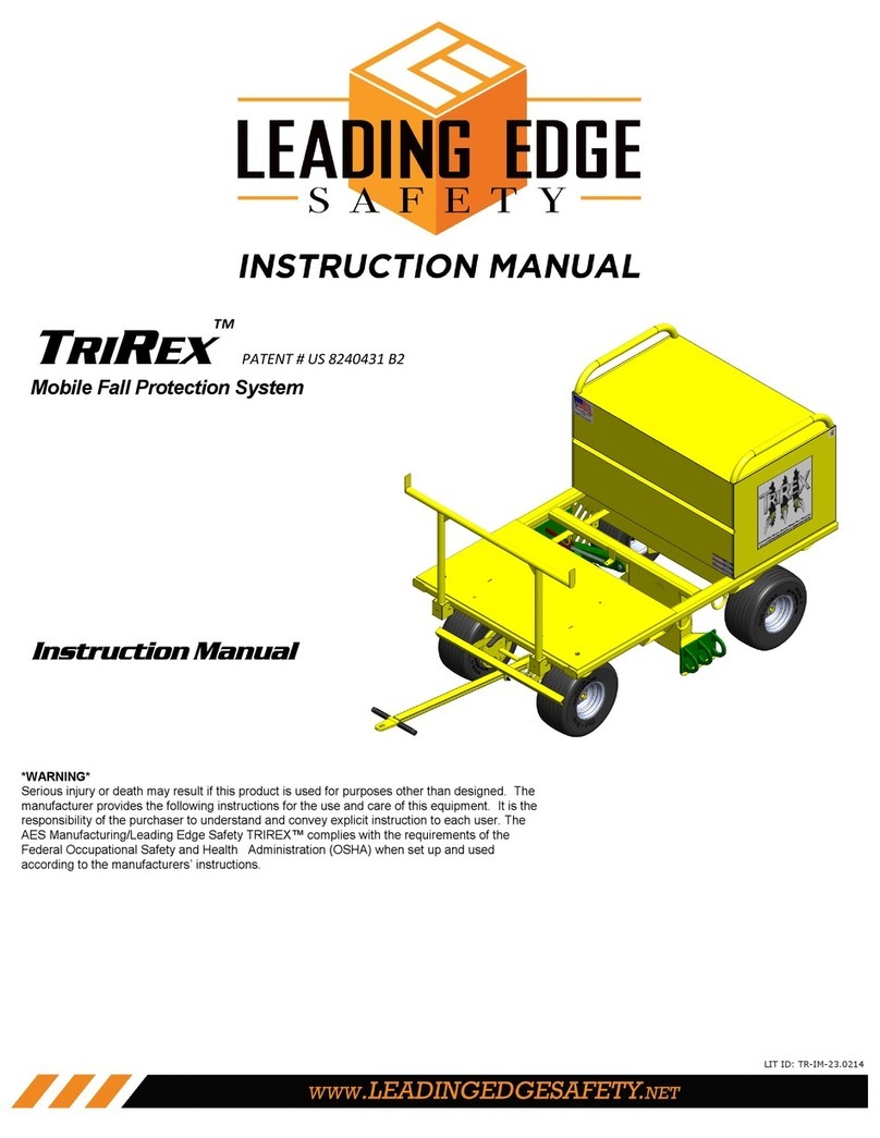
LEADING EDGE SAFETY TRIREX TR-000-02-18 User manual

TRIREX
™
PATENT # US 8240431 B2
Mobile Fall Protection System
*WARNING*
Serious injury or death may result if this product is used for purposes other than designed. The
manufacturer provides the following instructions for the use and care of this equipment. It is the
responsibility of the purchaser to understand and convey explicit instruction to each user. The
AES Manufacturing/Leading Edge Safety TRIREX™ complies with the requirements of the
Federal Occupational Safety and Health Administration (OSHA) when set up and used
according to the manufacturers’ instructions.
LIT ID: TR-IM-19.0722

TRIREX™INSTRUCTION MANUAL
1
TABLE OF CONTENTS
INTRODUCTION
Standards and Requirements____________________________ 3
Models______________________________________________ 4
Accessories__________________________________________ 5
Parts List____________________________________________ 7
GETTING STARTED
Wheel & Handles Assembly_____________________________ 13
Applications__________________________________________ 15
Definitions___________________________________________ 15
Use & Limitations_____________________________________ 16
Hoisting or Lifting_____________________________________ 18
General Safety_______________________________________ 18
Before Each Use______________________________________ 19
Positioning the Unit____________________________________ 19
Special Applications___________________________________ 21
Making Connections___________________________________ 22
Maintenance, Care & Storage____________________________ 23
In The Event of A Fall__________________________________ 23
APPENDIX
Appendix A - Troubleshooting____________________________ 24
Appendix B - Engagement Arm Shock Removal______________ 26
Appendix C - Engagement Arm Installation__________________ 29
Inspection & Maintenance Log____________________________ 33
E
N
G
L
I
S
H

TRIREX™INSTRUCTION MANUAL
2
LEADING EDGE SAFETY, LLC
TRIREX™ Instruction Manual
Published by Leading Edge Safety, LLC
North Kansas City, MO
TRIREX COMPLETE MOBILE FALL PROTECTION SYSTEM
is a registered trademark of
Leading Edge Safety, LLC
1345 Taney
North Kansas City, MO 64116
www.LeadingEdgeSafety.net
Copyright © 2019 by Leading Edge Safety, LLC
PRINTED IN THE UNITED STATES OF AMERICA
E
N
G
L
I
S
H

TRIREX™INSTRUCTION MANUAL
3
E
N
G
L
I
S
H
1.0 Standards and Requirements
1.1 The TRIREX™, manufactured by Leading Edge Safety LLC, is a dynamic anchor designed to
dissipate the energy generated from a fall event into the surrounding substrate and arrest a
fall. The TRIREX™ is capable of supporting a Maximum Arresting Force (MAF) of 1,800lbs for
up to (3) workers on approved substrates. Therefore, the TRIREX™ is an acceptable
component of a complete active fall arrest system and satisfies those requirements specified
in: ANSI/ASSE Z359.6-2009 “Specifications and Design Requirements for Active Fall
Protection Systems.”
1.2 Let it be noted that this mobile fall protection anchorage unit shall only be used as part of a
complete active fall protection system. Therefore, the following criteria must be met to satisfy
ANSI/ASSE Z359.6-2009:
1.2a Use of full body harness(s) in compliance with Z359.1-2007 “Safety Requirements for
Personal Fall Arrest Systems, subsystems, and Components”
1.2b Use of Lanyard(s) In compliance with Z359.13-2009 “Personal Energy Absorbers and
Energy Absorbing Lanyards”
1.2c Use of Connection(s) In compliance with Z359.12-2009 “Connecting Components for
Personal Fall Arrest Systems”
1.2d Use of Manufacturer’s Recommendations; the TRIREX™ shall not be
installed/positioned/utilized in a manner that violates the literature, instructions,
technical bulletins or any other documentation produced by Leading Edge Safety LLC.
1.2e Calculations by an authorized user (qualified person) to verify that the substrate, edge
distance, free fall distance, and the number of workers attached to cart satisfies those
requirements of ANSI Z359.6.
1.2f The use of component(s) used in combination with the TRIREX™ that are not covered by
ANSI/ASSE Z359 will not result in an acceptable Active Fall Protection System.
1.3 In addition to satisfying Z359.6, the TRIREX™ is also in compliance with OSHA’s “Fall
protection systems criteria and practices” (CFR › Title 29 › Subtitle B › Chapter XVII › Part
1926 › Subpart M › Section 1926.502). Section 1926.502(d)(15) requires that an anchor either
support 5,000 pounds per employee attached or is used as part of a complete personal fall
arrest system. Note that this anchorage unit is never intended to withstand a force of 5,000
lbs per user, but rather to be used as part of a complete personal fall arrest system.
Determining if this complete personal fall arrest system can maintain a safety factor of at
least (2) will require an authorized user to verify the above criteria.

TRIREX™INSTRUCTION MANUAL
4
E
N
G
L
I
S
H
TRIREX TR-000-01-18
MOBILE FALL PROTECTION SYSTEM
MODEL# TR-000-01-18
SINGLE 20 CUFT JOB BOX
3-PERSON FALL ARREST
2-PERSON FALL RESTRAINT
TRIREX TR-000-03-18
MOBILE FALL PROTECTION SYSTEM
MODEL# TR-000-03-18
DOUBLE 20 CUFT JOB BOX
3-PERSON FALL ARREST
2-PERSON FALL RESTRAINT
TRIREX TR-000-02-18
MOBILE FALL PROTECTION SYSTEM
MODEL# TR-000-02-18
SINGLE 20 CUFT JOB BOX
SINGLE 10 CUFT JOB BOX
3-PERSON FALL ARREST
2-PERSON FALL RESTRAINT

TRIREX™INSTRUCTION MANUAL
5
E
N
G
L
I
S
H
RAPTOR RESCUE
RMS-000-16
FALL RESCUE RETRIEVAL SYSTEM
MODEL# RMS-000-16
100 LF STAINLESS STEEL CABLE
INCLUDES RETRIEVAL POLE
COMPATIBLE WITH ALL TRIREX MODELS
AND CONFIGURATIONS, R1000, R2000
AND STINGER MODELS
RAPTOR ALERT
RAS-000-18
FALL ARREST ALERT SYSTEM
MODEL# RAS-000-18
130 DB SIREN
STROBE LIGHT
12v RECHARGEABLE BATTERY
COMPATIBLE WITH ALL TRIREX MODELS
AND CONFIGURATIONS, R1000, R2000
AND STINGER MODELS
SRL TRAY SRL-000-13
SRL TRAY GUIDE SYSTEM
MODEL# SRL-000-13
ORGANIZES AND GUIDES UP TO 3 SELF
RETRACTING LIFELINES
COMPATIBLE WITH ALL TRIREX MODELS
AND CONFIGURATIONS, R1000 AND
R2000 MODELS

TRIREX™INSTRUCTION MANUAL
6
E
N
G
L
I
S
H
ATTACHMENT POINT
RESTRICTOR
APR-000-12
ATTACHMENT POINT RESTRICTOR PLATE
MODEL# APR-000-12
COMPATIBLE WITH ALL TRIREX MODELS
LIMITS THE NUMBER OF ATTACHMENT
POINTS WHEN THE SUBSTRATE REQUIRES
A REDUCTION IN NUMBER OF USERS.
ICE PLATFORM
ICE-P-000-12
IN CASE OF EMERGENCY SAFETY PLATFORM
(PLATFORM ONLY)
MODEL# ICE-P-000-12
STORAGE FOR:
FIRST AID & MEDICAL SUPPLIES
(1) 5 GL WATER COOLER
(6) ABC FIRE EXTINGUISHERS
COMPATIBLE WITH ALL TRIREX MODELS AND
R2000 MODELS IN SINGLE JOB BOX
CONFIGURATION.
ICE PLATFORM
ICE-PE-000-12
IN CASE OF EMERGENCY SAFETY PLATFORM
(FULLY STOCKED)
MODEL# ICE-PE-000-12
24 PC FIRST AID KIT
(1) HEAT STRESS KIT
(1) BLOODBORNE PATHOGEN KIT
(1) SINGLE EYE WASH STATION
(1) 5 GL WATER COOLER
(6) ABC FIRE EXTINGUISHERS
COMPATIBLE WITH ALL TRIREX MODELS AND
R2000 MODELS IN SINGLE JOB BOX
CONFIGURATION

TRIREX™INSTRUCTION MANUAL
7
E
N
G
L
I
S
H

TRIREX™INSTRUCTION MANUAL
8
E
N
G
L
I
S
H

TRIREX™INSTRUCTION MANUAL
9
E
N
G
L
I
S
H

TRIREX™INSTRUCTION MANUAL
10
E
N
G
L
I
S
H

TRIREX™INSTRUCTION MANUAL
11
E
N
G
L
I
S
H

TRIREX™INSTRUCTION MANUAL
12
E
N
G
L
I
S
H

TRIREX™INSTRUCTION MANUAL
13
E
N
G
L
I
S
H

TRIREX™INSTRUCTION MANUAL
14
E
N
G
L
I
S
H

TRIREX™INSTRUCTION MANUAL
15
E
N
G
L
I
S
H
2.0 APPLICATIONS
2.1 The TRIREX™ is designed to be used as an anchorage as part of a complete mobile fall protection system. The
TRIREX™ may be used where worker mobility and fall protection are required. See WWW.OSHA.GOV for all
regulations and standards.
2.2 The TRIREX™ allows for up to three workers to be tied-off simultaneously for fall arrest to the Fall Arrest
Attachment Points and an additional two workers tied-off simultaneously for fall restraint to the Fall Restraint
D-Rings. See the following definitions (Section 3.0):
FALL RESTRAINT D-RINGS
FALL ARREST ATTACHMENT POINTS
3.0 DEFINITIONS:
3.1 Fall Restraint System – A fall restraint system (FRS) prevents the user from falling. The system is comprised of
a body harness along with an anchorage, connectors and other necessary equipment. The components typically
include a lanyard and also may include a lifeline and other devices. The TRIREX™ can be used as an
anchorage in a fall restraint system for up to two workers.
3.2 Personal Fall Arrest System – A personal fall arrest system (PFAS) arrests a fall after a fall has begun. The
system is comprised of an anchorage, connectors, and a body harness and may include a deceleration lifeline, or
suitable combinations. Note that a PFAS does NOT prevent a fall from occurring. The TRIREX™ can be used
as an anchorage in a PFAS for up to three workers. A Personal Fall Arrest System must meet the following
OSHA requirements:
Limit maximum arresting force on an employee to 1,800 pounds when used with a body harness;
Be rigged so that an employee can neither free-fall more than 6 feet (1.8 meters) nor contact any lower level;
Bring an employee to a complete stop and limit maximum deceleration distance an employee travels to 3.5
feet (1.07 meters); and
Have sufficient strength to withstand twice the potential impact energy of an employee free-falling a distance
of 6 feet (1.8 meters) or the free-fall distance permitted by the system, whichever is less.
3.3 Anchorage — An anchorage is a secure point of attachment for lifelines, lanyards, or deceleration devices. The
TRIREX can be used as an anchorage.

TRIREX™INSTRUCTION MANUAL
16
E
N
G
L
I
S
H
4.0 USE AND LIMITATIONS
4.1 LOAD REQUIREMENTS—Before the TriRex is hoisted to any roof surface, the user must verify that the deck
assembly can accommodate the live load requirements of the TriRex.
4.2 APPROVED SUBSTRATES:
BUILT-UP ROOFING (BUR)4 MODIFIED BITUMEN4
THERMOPLASTIC POLYOLEFIN (TPO)4ETHYLENE PROPYLENE DIENE MONOMER (EPDM)4
POLYVINYL CHLORIDE (PVC)4BALLASTED SINGLE-PLY MEMBRANES4
BUILT-UP ROOFING (BUR) AND GRAVEL4INVERTED ROOF MEMBRANE ASSEMBLY (IRMA)4
ROOF COATINGS 4
PLYWOOD HIGH DENSITY FIBERBOARD3,6
DENSDECK® 3,6 GYPSUM BOARD3,6
POLYISOCYANURATE (ISO)3,6 EXPANDED POLYSTYRENE (EPS)3,6
EXTRUDED POLYSTYRENE (XPS)3,6 SPRAY-APPLIED POLYURETHANE 3,6
METAL DECK (22GA AND 20GA)METAL DECK (18GA1,2,6,8)
LIGHTWEIGHT CONCRETE CONCRETE DECK1,2,8 (4000-6000PSI)
TOPSOIL—COMPACTED GYPSUM DECK
ASPHALT PAVEMENT GRAVEL—COMPACTED
PANELIZED SLAB FORMWORK7,8
FLAT SURFACES AND UP TO 2:12 SLOPE.
DO NOT USE THE TRIREXTM ON THE FOLLOWING SUBSTRATES:
ICE
SNOW
TECTUM DECK5
METAL DECKS LESS THAN 22GA5 OR GREATER THAN 18GA5, 6
1REDUCE MAXIMUM NUMBER OF USERS IN FALL ARREST TO 2 (TWO).
2REDUCTION IN NUMBER OF USERS IN FALL ARREST DOES NOT APPLY IF AN APPROVED INSULATION(S) THICKNESS IS 3.875” OR GREATER. FIG 4-1
3WHEN MECHANICALLY FASTENED OR ADHERED TO AN APPROVED SUBSTRATE.
4WHEN USED AS PART OF A COMPLETE ROOF ASSEMBLY.
5SUBSTRATE IS ALLOWABLE WHEN COVERED WITH 3/4” PLYWOOD SECURED WITH A MINIMUM OF EIGHT (8) FASTENERS. FIG 4-2
6SUBSTRATE IS ALLOWABLE WHEN TOTAL INSULATION THICKNESS IS GREATER THAN 3.875” OR USED WITH AN APPROVED METAL DECK. FIG 4-2
7FALL RESTRAINT ONLY—MAXIMUM 2 USERS
8UTILIZE ATTACHMENT POINT RESTRICTOR PLATES TO ELIMINATE OR LIMIT THE NUMBER OF USERS IN FALL ARREST
DensDeck® is a registered trademark of Georgia-Pacic Gypsum, LLC.
Approximate Unit Weight: 1000 lbs
Tire Footprint: 3” x 5”
Approximate Weight per Tire: 250.0 lbs
Approximate Pounds per SqIn: 16.66 psi
49.53”
19.64” 36.12”
47.56”

TRIREX™INSTRUCTION MANUAL
17
E
N
G
L
I
S
H
INSULATION
DECK
FIG. 4-1
3/4” PLYWOOD
48” X 96”
FASTENER 2” MIN. FROM
PLYWOOD EDGE
FIG. 4-2
4.3 CAPACITY: The TRIREX™ Mobile Fall Protection System is designed for a maximum of three per sons for
fall arrest and two for fall restraint with a combined weight (clothing, tools) of no more than 310 lbs. per
person. No more than five persons may be connected to the TRIREX™ at any time.
IMPORTANT: DO NOT begin work for which fall protection is required until the TRIREX™ unit and
corresponding Fall Restraint System (FRS) or Personal Fall Arrest Systems (PFAS) have been
completely installed. Do NOT disable any part of the FRS or PFAS, including the TRIREX™
unit, or reposition the TRIREX™ unit, until work for which fall protection is required has
ceased.

TRIREX™INSTRUCTION MANUAL
18
E
N
G
L
I
S
H
5.0 HOISTING OR LIFTING
5.1 Loads may slip or fall if the TriRex is not hoisted or lifted properly and may result in injury or death.
5.2 Never hoist or lift the TriRex if any of the hoisting rings or fork pockets are damaged.
5.3 Never hoist or lift the TriRex with unsecured materials on the unit.
5.4 Ensure any auxiliary equipment is properly and securely attached to the TriRex before hoisting or lifting.
5.5 The TriRex shall be hoisted or lifted following good industry practices, State and Federal Regulations, and
hoisting and lifting equipment manufacturer’s guidelines.
5.6 The TriRex was designed be to hoisted by a crane or lifted by a forklift and is equipped with both hoisting guide
rings and fork pockets.
HOISTING GUIDE RING HOISTING GUIDE RINGFORK POCKET
6.0 GENERAL SAFETY
6.1 USE COMMON SENSE! Most accidents can be avoided by using common sense and focusing on the job
at hand.
6.2 The TriRex should not be used by persons whose ability or alertness is impaired by fatigue, intoxication,
prescription or illegal drugs, or any other physical or mental cause that may expose the user or others to injury.
6.3 Always wear proper Personal Protective Equipment.
6.4 Keep hands and feet clear of moving parts including the Engagement Arm.
6.5 Do not use the equipment near electrical lines.
6.6 Do not allow passengers to ride on the safety cart.
6.7 Do not use on wet, slippery or icy substrates.

TRIREX™INSTRUCTION MANUAL
19
E
N
G
L
I
S
H
6.0 GENERAL SAFETY (Continued)
6.8 Only use the TriRex on substrates and assemblies for which it has been tested. (Reference Sect 4.2 Approved
Substrates)
6.9 Always lower the handle to engage the brake when the unit is not being moved.
6.10 Always uses caution and common sense when moving the unit. Additional workers may be needed to safety
move the unit when additional materials, tools or equipment have been added to the unit.
7.2.E Ensure all safety labels are present and fully legible. (Reference parts list pages 7-10)
7.2.F Check for corrosion on entire unit.
7.2.G Check Engagement Arm for freedom of movement.
7.2.H Check 3-Ring Attachment Point for freedom of movement.
7.2.I Ensure the Engagement Arm Locking Mechanism is in the proper spring loaded position.
7.2.J DO NOT USE DAMAGED EQUIPMENT OR EQUIPMENT THAT HAS BEEN MODIFIED.
7.2 Inspect the unit for any damage. A maintenance log has been
provided in this manual that may be copied and used to track
inspections and damage.
7.2.A Check for loose, bent or damage parts, including the talon
and rake tips of the engagement arm. FIG 7-2
7.2.B Check welded connections for visible distortion, cracks or
other damage.
7.2.C Check Tie-off Rings for distortion or damage.
7.2.D Check cables for rusting and wear. DO NOT use if cable
or cable connections have been damaged. TALON
RAKE
FIG 7-2
7.0 BEFORE EACH USE
7.1 Before using this unit, a rescue plan and procedure in accordance with OSHA Standards must be in place to
ensure prompt rescue in the event of a fall.
8.0 POSITIONING THE UNIT
8.1 Verify that the substrate the unit is to be used on is acceptable (Reference Sect 4.2 Approved Substrates) and
the entire working surface has the strength and structural integrity to safety support both the workers and the
unit.
8.2 Position the unit with the Fall Arrest
Attachment Point side 12’ - 15’ away and
parallel to the working edge to maximize the
work zone. FIG 8-2a
The unit may be used a minimum of 4’ from
the leading edge, maintaining a maximum
work zone of 45˚ or 2’ from the center of the
attachment point. FIG 8-2b
The unit may be used a maximum of 30’
from the leading edge, however the work
zone may not exceed 15’ from the center of
the attachment point. FIG 8-2b FIG 8-2
This manual suits for next models
7
Table of contents
Other LEADING EDGE SAFETY Protection Device manuals