THOR SMART RACKGUARD iQ User manual
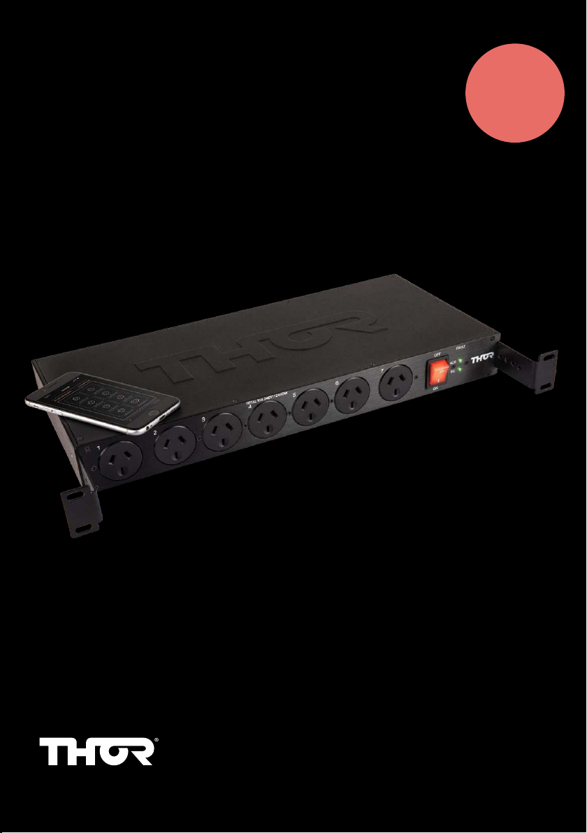
SMART RACKGUARD iQ RF11iQP
8 X REMOTE CONTROLLED
DUAL CIRCUIT PROTECTION
AND FILTRATION
USER MANUAL
thortechnologies.com.au
MODEL: RF11iQP

2RF11iQP Warranty and User Manual
RF11iQP Warranty & User Manual
Thor Technologies Pty Ltd reserves the right to alter or change the specifications and/or product
as and when deemed necessary to keep in line with the Company policy of ongoing improvement
in research, development and features of the product range.
1. INTRODUCTION
Thank you for choosing the THOR Smart Rack Guard iQ (RF11iQP).
The Smart Rack Guard iQ (RF11iQP) has been designed with industry leading technology for the
integration of secure IP based monitoring functions and has the ability to communicate via a web
browser application using Microsoft Edge, Firefox, Chrome or Safari. This remote access will allow
users, particularly service technicians, immediate advice via email of any power loss causing the
controller to reboot. This manual will explain how to set up and use the features of this product to
ensure integrity and security standards are maintained.
Purpose
Why is there a need to communicate with a filtered surge protector? Today many electrical
appliances have the ability to be turned on or off remotely. In many instances service personnel
can monitor systems and equipment to ensure they are performing correctly. Instant advice of a
problem can save on downtime and reduce associated call outs. Early detection to faults and the
ability to reset equipment remotely can relieve expensive call out costs.
The RF11iQP can alert via email should the product sustain any damage from a power surge or
other high voltage incident. If inbuilt power circuits are affected and the system has had to self
reboot, an email will be sent immediately to advise of such an event.
Once the email has alerted a service technician of a potential problem (providing power is
correctly restored and the RF11iQP has not suffered major damage) if connected equipment is not
functioning correctly service personnel are able to log in and reset this equipment. The ability to
turn each circuit on or off becomes an invaluable time and cost saving function.
RF11iQP may still need a follow-up visit to the site to ensure the Power LEDs are still both ‘Green”
If the LEDs on the front panel are both not ‘Green’ then damage has been sustained and the
product needs replacing.
Conventions
The product programming software will run a web server that serves simple and uncluttered HTML
and/or XML pages to indicate system status. Industry Standard Internet Protocols are used. In
addition the software has inbuilt email functionality.

3RF11iQP Warranty and User Manual
2. OVERVIEW
The RF11iQP has two circuits. One circuit set contains 7 individually controlled Australian pin
outlets while the other circuit set contains a single control for 4 IEC outlets giving a combined 11
outlet configuration. Each circuit has spike and surge protection as well as filtered technology to
ensure safe and clean power is supplied to any connected devices.
Given the nature of rack applications often being in mission critical installations, the design of
the RF11iQP if there has bean a power incident that forces the unit to automatically reboot,
the RF11iQP provides an immediate alert re the incident which highlights that it has reduced or
exhausted its protection capacity but it will still continues to allow power through. This allows
service technicians to work on a replacement unit while not affecting the site operations.
2.1 FEATURES
Current Limits
240VAC Total unit current is 10A Max
Each Australian pin individual outlet (1 – 7) has capacity to supply 10A maximum per outlet; REAR
CIRCUIT 8 – IEC x 4 outlets combined can supply 10A output in total.
NOTE: The total output across all 11 outlets can only be maximum of the unit, which is 10A.
Individually controlled switchable circuits
Seven individually controlled Australian pin outlets and a single control for 4 IEC outlets via the
web browser available through a PC or via a Smartphone. This allows the user to select outlets to
be switched off when not in use or required remotely as well as controlling individual circuits if a
fault condition is apparent while allowing other sections to still remain operational (Providing the
RF11iQP unit is fully functioning and has not sustained any damage).
NOTE: If output 1 has an auto-restart time set, it will definitely be switched on at reset regardless
of what it was doing prior to reboot. Only outlets that were ‘ON’ before an event/power outage will
automatically be switched ‘ON’ when unit is restarted. For example, if only outlets 3 and 4 were ‘OFF’
before an event/power outage then these will be the only outlets that will remain off when the unit is
restarted. To activate the outlets that are “OFF” you must use the web browser through a PC or via
a Smartphone to switch the outlets “ON”. The unit MUST be LAN connected and all the parameters
in your browser and server network set correctly. See the section on setting up the web browser
‘Configuration’ through a PC or via a Smartphone web browser outlined later in this booklet.
Soft Start
The RF11iQP has an in built ‘Soft Start” feature to allow the unit to be switched on without causing
a major overload of the 10A Circuit Breaker. If there has been an outage the RF11iQP will switch
back on incrementally with a few milliseconds between each outlet turning back on (that was
previously on before outage).
OTA (Over The Air Programming)
The RF11iQ has the added feature of OTA Firmware upgrades through the Configuration Screen
by using a downloadable file from Thor Technologies (*.Bin) reducing the need to return the unit to
Thor Technologies for upgrades. See ‘Firmware’ in this manual.
Individual Naming of Outlets
The RF11iQP allows for each Outlet to be individually named in the ‘Configuration’ allowing for easy
tracing of connected equipment.
4RF11iQP Warranty and User Manual
3. INSTRUCTION
Procedures
Please note whilst effort has been made to simplify the setup, some of these procedures have
been produced assuming an experienced IT person is carrying out the configuration.
Knowledge of networking protocols would assist greatly with understanding the configuration.
3.1 IP BASED MONITORING
It’s highly recommended to connect the RF11iQP to a network with a DHCP server (generally your
internet router).
To log into the RF11iQP admin console, please enter : http://RF11iQP.local in the top address field
of a browser such as Chrome, Edge, Firefox or Safari and the following screen should appear.
The hostname RF11iQP.local can be entered with or without connecting to a DHCP server. Without
DHCP, your PC will communicate via Multicast DNS or mDNS. The default IP address is 10.1.1.18.
NOTE:If configuring multiple RF11iQP suggest use the default (RF11iQP.local) to get the initial
connection and then change the hostname so other devices can then be detected.
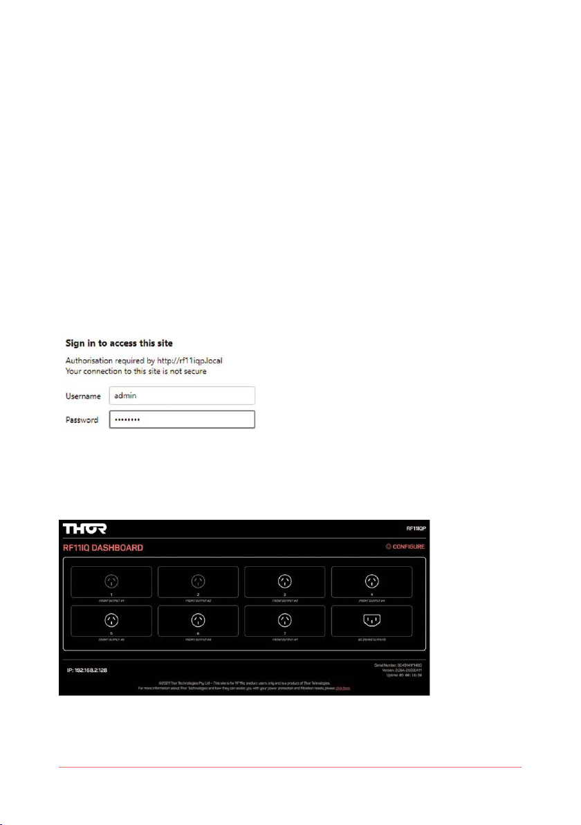
Enter text to field User name: admin
•Enter text to field Password: THORRF11
•Press “OK” or “Log In” button (once Username and Password fields are populated) and this
screen should appear below.
You are now looking inside the browser of the RF11iQP. Icons show which outlets are energised
and allow you to toggle the outputs on or off. Outlets 1 & 2 are currently OFF (Grey)... ALL OTHER
OUTLETS ARE ON (White).
5RF11iQP Warranty and User Manual
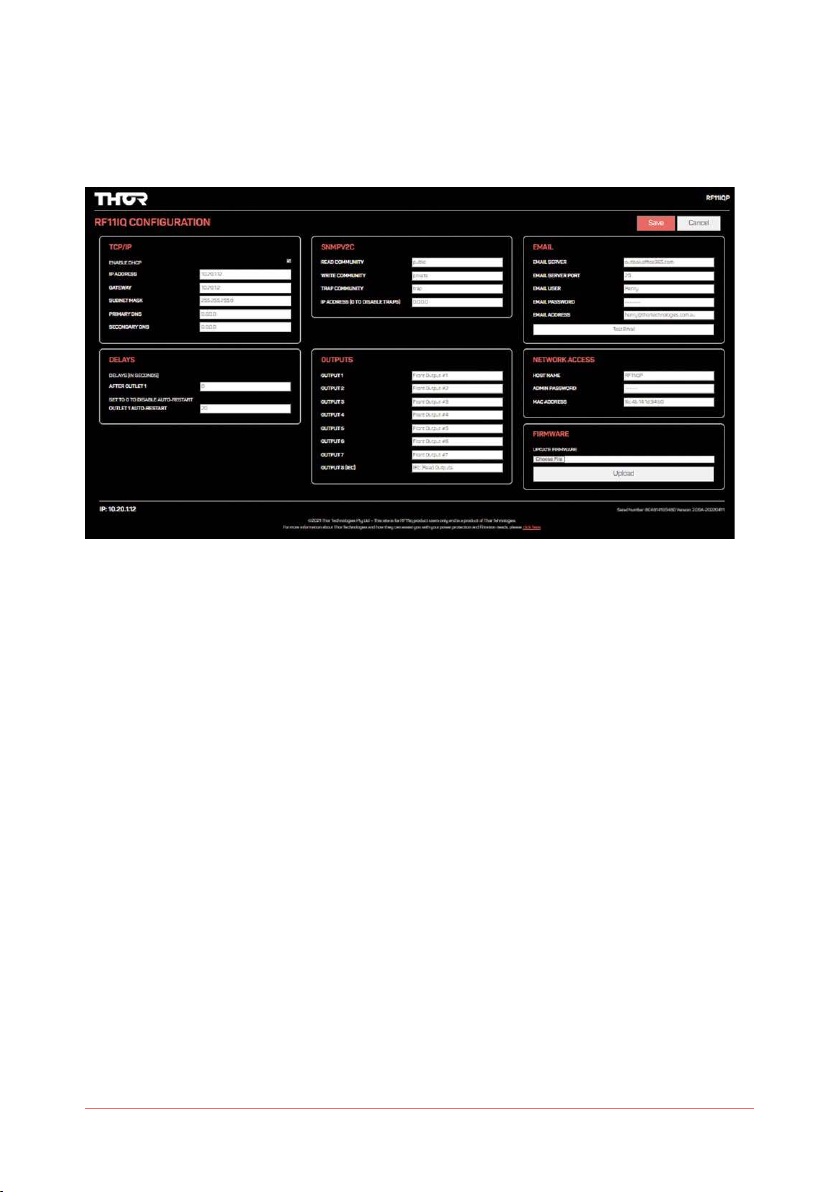
3.2 CONFIGURATION
Please select “Configure” button on the bottom of the page to access the network settings. This
will allow you to change the default IP address, User name and password and email configuration.
Changing these settings is strongly recommended to maintain security protocols.
3.2.1 Enable DHCP
When enabled, the device uses Dynamic Host Configuration Protocol to determine network
settings. When DHCP is enabled you may not edit the network settings. If you open the
configuration screen when DHCP is already enabled, the disabled fields will show the settings
currently issued to the unit from your DHCP server. (Note - when DHCP is disabled the current IP
address will be retained even after a restart)
IP Address
The IP address of the unit.
Gateway
The IP address of the default gateway, i.e. the address to which any traffic not destined within the
local network will be sent for further routing.
Subnet Mask
The bitmask which determines what portion of the IP address describes the network, and what
part identifies a node within the network.
Primary DNS
Address of the main DNS server. This is required to translate URLs to IP addresses (eg mail.
yourcompany.com to 10.1.1.13).
Secondary DNS
Address of the backup DNS server, used if communication to the primary server fails.

6RF11iQP Warranty and User Manual
3.2.2 Delays
After Outlet 1
On power-up, this allows for a delay between the first outlet and the rest, to allow (for example) the
router or DHCP server to boot ready to serve the other devices when they in turn are powered up.
Outlet 1 Auto-restart
Setting the Outlet 1 Auto Restart Delay allows for Outlet 1 to automatically restart after the
preset delay period (sec). Placing your router on Outlet 1 and setting this delay means that you
can remotely repower your router using the web browser and, after the delay, have it start up
again. If the Outlet 1 Auto Restart is set to “0”. Then the feature is disabled and Outlet 1 will not
automatically restart.
3.2.3 SNMP
The RF11iQP supports Simple Network Management Protocol (SNMP ) version 2C management
and traps for connection into network management systems. The community names can (and
should) be changed for slightly improved security. If the IP address in this section is set, alerts
(traps) will be sent to the specified IP address on powerup.
The MIB for the RF11 can be downloaded from the device at http://RF11iQP.local/RF11_MIB.mib
This MIB allows for interrogation of network and outlet state, and allows (to the write community)
the ability to switch outlets on and off.
3.2.4 Outputs
Each output may be assigned a label which is displayed on the status screen and mobile apps to
help identify what is connected to each output.
3.2.5 Email
Email Server
The IP address or name (eg mail.yourcompany.com) of the SMTP server used to relay outgoing
messages.
Email Server Port
The port number on which your email server accepts inbound SMTP connections for email.
Traditionally 25, modern servers use 587. Sometimes, 465 or 2525 may be used. If none of these
work please consult your email/ SMTP server provider for the recommended settings, and ensure
outbound ports aren’t blocked with your ISP.
Email User & Email Password
The user id and password the device will use to log onto the SMTP server. Note that only clear text
logins are supported (no SSL etc).
Email Address
The email address to which alerts will be sent.

7RF11iQP Warranty and User Manual
3.2.6 Network Access
Host Name
The name of the device on the network. It will be included in alert messages to help you identify
which device is having a problem.
Admin Password
Required to access the web interface for the device. Username is fixed as “admin”, the password
defaults to “THORRF11” on factory reset.
MAC Address
This is the low-level hardware address of the device, which must be unique on your network and
any network containing a machine trying to access the device.
The factory supplied MAC Address is guaranteed unique worldwide. It is recommended that you
do not change it unless you have a very specific reason for doing so.
mDNS (Multicast DNS)
The RF11iQ has had the mDNS capability added to help with name resolution in smaller networks
without routers/DHCP servers.
The device’s mDNS name will be <hostname>.local, by default RF11IQP.local.
Security: Although every effort is made to maximise Internet security within the unit, the
capabilities of such a small device are limited, thus it is recommended that the unit be operated
with an external firewall and other such security measures. The other advantage of this is that the
firewall will be more up to date and better integrated with the site security policy.
3.2.7 Firmware
Choose File
Click on this button to locate a Thor RF11iQP *.BIN (binary) file to upload into the firmware.
Upload
Once a bin file has been chosen, click upload to program the new firmware into the unit. Do not
disconnect network or power until the operation is complete.
Save
Click save to store any changes into the device’s permanent Flash memory.
You will then be re-directed to the status page.
Note that the unit must be restarted for any changes to network configuration to take effect.
If you have changed the Admin Password, the status page will then ask you for the new username
and password.
Cancel
Aborts changes and returns to the status screen.

8RF11iQP Warranty and User Manual
3.2.8 Remote Access and Security
Remote access :
RF11iQP is listening on ports 80 and 443 (http and https, respectively).
Port forwarding on your firewall/router would point to 80.
Security
It’s recommended to restrict remote access to only trusted external IPs
For example : if using port forwarding for external access, and opening ports 8081 forwarding
8081 to 80 of the IP address of the RF11iQP, external access to port 8081 is recommended to be
limited too.
3.3 MAIN PAGE
The main page shows a button for each output switch and its current status. Clicking on an icon
will toggle the output.
3.4 FACTORY RESET
If a unit requires a “Factory Reset”, the user must follow these instructions.
•Turn OFF power to the unit (Power ON / OFF Switch on the Front Panel)
•Push and hold the CPU RESET Switch (Located on the rear of the unit near the LAN
Connector) and Turn ON the unit. (Power ON / OFF Switch on the Front Panel) Keep holding the
CPU RESET Switch for 10-15 seconds until you hear the relays sequence through (Click...Click...
Click), then release the CPU RESET switch.
The unit will now be reset to the factory default firmware and configuration.

9RF11iQP Warranty and User Manual
3.5 OPERATIONAL AND PROTECTION STATUS
RF11iQP PROTECTION FUNCTIONING CORRECTLY
Power On LEDs. ‘AUS’ – Green, ‘IEC’ – Green.
PROTECTION NOT FUNCTIONING
If any condition displayed on the LED’s is other than both ‘Green’ please contact Thor
Technologies immediately.

10 RF11iQP Warranty and User Manual
3.6 SMARTPHONE APP
Access
Enter the hostname or IP address into your Smart phone web browser.
e.g. http://RF11iQP.local
Operation
The RF11iQP has a revolutionised remote control of a power filtration
& distribution system using a Smartphone web browser
It is the same as the web server page but oriented to fit a Smartphone
screen
•Indication of circuits that are turned “ON” (White)
•(Circuit 1) - Aus 1 Outlet Preset Auto switch ON Delay and Manual OFF/
ON Control
Delay is set up in the Configuration Page ‘DELAYS’
•(Circuit 2-7) - Aus 2-7 Outlets OFF/ON CONTROL
•(Circuit IEC) - IEC IEC X 4 Outlet Alarm indication and reset
•(Circuit 2-7 & IEC) can be set to turn “ON” after Circuit 1 by setting a preset delay.
The ‘Delay period is set up in the Configuration Page ‘DELAYS’
The RF11iQP can also be Configured by selecting ‘CONFIGURE’ now from the SMARTPHONE Web
Browser’
Configuration
The RF11iQP can also be configured from the Web portal in the same WAY as on a standard PC.
Image samples below... (Screen split over 4 images)

11RF11iQP Warranty and User Manual
4. APPLICATION NOTE (HOW TO TURN ON/OFF STAND-BY POWER)
Use of HTTP interface to remotely control the RF11iQP unit.
The RF11iQP exposes an HTML interface via the /cpan.cgi url which allows the user to power up/
down the output and enable the buzzer for faults on each circuit. It also allows the user to silence
the buzzer if it is active.
The full syntax is as follows:
http://<address>/cpan.cgi?param=<p>&value=<v>
<address>
The address of the unit, either as an IP address (eg 10.1.1.7) or as a DNS name if this has been
configured (eg rf11.yourcompany.com)
<p> <v>
p<n> Circuit <n> power.
0 Power off.
1 Power on.
Example
To turn circuit 1 off:
“http://10.1.1.7/cpan.cgi?param=p1&value=0”
Note that the login details are still required to perform these commands, as you will discover if you
enter them straight into the address bar of your browser.
The authentication method used is BASIC, the username is fixed as “admin” and you choose the
password – which defaults on factory reset to THORRF11.

12 RF11iQP Warranty and User Manual
Given that the device has a HTML interface which displays status and provides a user interface
for this cpan.cgi command interface, the URL is not especially useful on its own. When, however, it
is combined with the cURL utility (available for Linux, Mac and Windows) it means that any of these
functions on the unit may be operated from the command line on any application.
NOTE: These methods all rely on the IP address remaining valid. It is recommended that you
either configure your RF11iQP with a static IP address or assign it a permanent lease in the
DHCP server if these scripting methods will be used long term, as by default the DHCP server
may change the assigned IP address periodically with lease renewals.
The syntax required for using cURL in this manner is as follows:
curl --user admin:<pass> “http://<address>/cpan.
cgi?param=<p>&value=<v>”
<address>, <p> and <v> are the same as above.
<pass> is your currently configured admin password for the unit.
Make sure you wrap the url in double quotes.
cURL is a built-in command on Linux, BSD and the Mac. There are several implementations
available for Windows and a simple search will reveal them.
Once this is configured, you can use other applications or utilities to drive (for example) the
outputs of the RF11 units based on a schedule or other network management alarms and so on.
A classic example – some devices may only be required during the day. By using the task
scheduler (Windows), cron (linux/BSD) or launchd (Mac) you can power up your rack in the morning
and shut it down in the evening to conserve power.
NOTE: Obviously, you will need to ensure that the appropriate shut-down of any equipment
powered off the controlled circuit has been performed or that the equipment is tolerant of
repetitive, unexpected power outages before using this procedure.
Linux Example
From a terminal type:
export EDITOR=<editor>
<editor> could be vi, nano, whatever your favourite text editor is.
sudo crontab -e
You’ll need to enter your password, and be an admin on the machine. Add the following lines:
0 9 * * 1-5 curl --user admin:THORRF11 “http://10.1.1.58/cpan.
cgi?param=p1&value=0”
0 17 * * 1-5 curl --user admin:THORRF11 “http://10.1.1.58/cpan.
cgi?param=p1&value=1”
Save and exit.
Now, at 0 minutes past 9am, every day of the month and every month, on days of week 1-5
(Monday to Friday), the output of circuit 1 will be switched on. Similarly, at 5pm on these days it will
be powered down.

13RF11iQP Warranty and User Manual
Windows Example
Start by finding a version of curl that works on your system. A good place to start is
http://curl.haxx.se/download.html. Download and copy the curl.exe into your
c:\windows\system32 directory. You may need to do this by running an explorer or cmd shell
as administrator. Click Start, search for “cmd”, right click on cmd.exe when it appears and run as
administrator, then copy from there. You can do the same with explorer.exe instead of cmd.exe
Ensure that the curl command line call works, by clicking Start, searching for “cmd” and running
cmd.exe. Enter the curl command and make sure the RF11iQP switches on or off correctly.
Now set up the schedule. Start->Control Panel, System and Security, Administrative Tools, Task
Scheduler.
Create a basic task named “RF11iQP Startup”, with a weekly trigger, starting at 9:00:00am and
recurring every 1 week, with Monday through Friday checked. The task should start a program
curl.exe, with the --user and url arguments to power up the circuit added.
Create a second task named “RF11iQP Shutdown” which is the same, except it should start at
5:00:00pm and arguments set to power down the circuit.
YOU’RE DONE!
Mac Example
OS-X still supports the crontab utility as used by the linux example, although it has been
deprecated in favour of launchd.
The configuration of launchd to call the curl utility is outside this scope: please refer to the Apple
knowledgebase on the subject (searching for “launchd.plist” may also yield some good results).

14 RF11iQP Warranty and User Manual
5. EXTERNAL EARTH CONNECTION
Add external earth
Terminate cable with a vinyl-insulated ring terminal similar to kst drvs5-1 or similar
with a hole ø to fit m4 stud ...
Hook-up wire 300v grn / yel or yel / grn min 16awg ... Similar to alphawire ul 1007 3057
Figure 2
OPTIONAL
An external earth can be added to selected RF11 Series products to meet earthing requirements
with rack installations… use Figure 2 as a guide
1. Remove the TOP M4 nut but do not discard, keep for step 3.. DO NOT LOOSEN OR REMOVE
THE SECOND NUT
2. Connect a correctly selected and terminated cable. See notes in picture.
3. Refit the M4 nut securely so that the ring terminal is held tightly in place.
15RF11iQP Warranty and User Manual
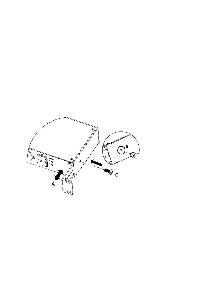
6. BRACKET ADJUSTMENT INSTRUCTIONS
ADJUSTABLE RACK MOUNTING BRACKET
The RF11 Series has a unique adjustable Rack Mounting Bracket to be set by the end user.
(A) The bracket can be adjusted to accommodate the depth of the plugs that are connected. The
bracket has a stop point limit and can be adjusted from flat, level with the front panel to its
maximum point of travel as shown by the arrows in Figure 1 A.
(B) Align the hole on the side of the unit with the hole of the Rack Mounting Bracket as shown in
Figure 1B.
(C) Fit the M6 Screw provided in the packet to secure the bracket. The hole in the bracket is
pretapped to suit the screw. One screw per bracket. As shown in Figure 1 C.
IMPORTANT NOTE:
Care should be taken that the screw is correctly positioned before attempting to screw it into
position to avoid cross threading.
The process is repeated on the other side of the unit.
Figure 1
Additional ‘Screws and Nuts (X 4)’ are provided to allow the end user to mount the RF11 product in
a rack. In most cases you will find that the racks systems have their own nuts built in but if they
do not then theses can be used.

16 RF11iQP Warranty and User Manual
7. REFERENCE
Error messages and causes:
Appendix A - Glossary
Title Title
Appendix B - Index
Title Title

17RF11iQP Warranty and User Manual
6 YEAR PRODUCT WARRANTY
Congratulations on purchasing Australia’s finest power protection.
Unless otherwise stipulated in a separate and specifically superseding Product Guarantee, all
THOR power protection products are guaranteed for a period of six (6) years from date of original
purchase against damage or failure due to faulty components or workmanship. Our goods come
with guarantees that cannot be excluded under the Australian Consumer Law. You are entitled to a
replacement or refund for a major failure and compensation for any other reasonably foreseeable
loss or damage. You are also entitled to have the goods repaired or replaced if the goods fail to be
of acceptable quality and the failure does not amount to a major failure.
Notice to New Zealand Consumers
Our goods come with guarantees that cannot be excluded under the Consumer Guarantees Act
1993. This warranty should not be construed as any attempt to contract out of or exclude any
or the guarantees available to any consumers under this Act provided that you agree that the
provisions of the Consumer Guarantees Act 1993 will not apply if you are acquiring the goods for
the purpose of a business.
This warranty shall not cover normal and expected wear and tear, damage, malfunction or failure
resulting from accident, misuse or misapplication, improper or unauthorised repair, neglect,
modification or use of unauthorised replacement parts or accessories, operation of the unit
beyond its technical and environmental specifications, infestation by insects or vermin or
interfacing supplied by the customer or improper voltage. The warranty shall be void if the rating
label or date code has been removed or altered.
This THOR product is sold by the Dealer or Agent as principal. The Dealer or Agent has no
authority from THOR Technologies Pty Ltd to express any additional warranty or guarantee on the
Company’s behalf except as herein contained. This warranty only applies to the purchase and use
of the product in Australia and New Zealand.
To the extent permitted by the relevant legislation in Australia and New Zealand, THOR
Technologies Pty Ltd will not accept or have any other responsibility or liability whatsoever
for negligence or liability for incidental, consequential, indirect or special damages, including
without limitation, loss of actual or anticipated revenue or loss of data or for data being rendered
inaccurate. You must bear any expense you incur in claiming this warranty.

18 RF11iQP Warranty and User Manual

19RF11iQP Warranty and User Manual

20 RF11iQP Warranty and User Manual
THOR TECHNOLOGIES PTY LTD
PO Box 95, Karrinyup, Western Australia, Australia 6921
thortechnologies.com.au RF11iQP v1.3 – 05/22
This manual suits for next models
1
Table of contents
Other THOR Protection Device manuals


