Leading Edge 5630-1RDP User manual

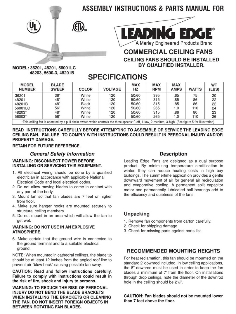
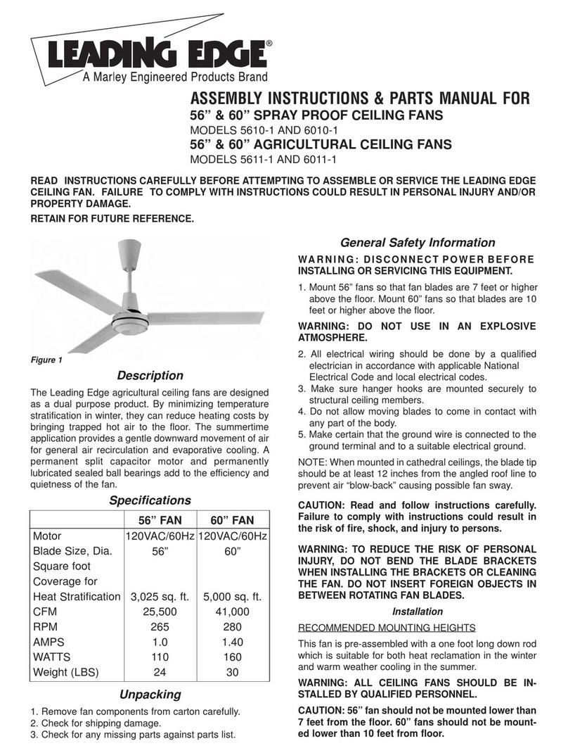
ASSEMBLY INSTRUCTIONS & PARTS MANUAL FOR
REVERSIBLE CEILING FANS
CEILING FANS SHOULD BE INSTALLED
BY QUALIFIED INSTALLER.
SPECIFICATIONS
MODEL: 5630-1RDP
MODEL
NUMBER BLADE
SWEEP COLOR VOLTAGE MAX
HZ MAX
RPM MAX
AMPS WATTS WT
(LBS)
5630-1RDP 56” White 120 50/60 275 1.0 110 24
READ INSTRUCTIONS CAREFULLY BEFORE ATTEMPTING TO ASSEMBLE OR SERVICE THE LEADING EDGE
CEILING FAN. FAILURE TO COMPLY WITH INSTRUCTIONS COULD RESULT IN PERSONAL INJURY AND/OR
PROPERTY DAMAGE.
RETAIN FOR FUTURE REFERENCE.
General Safety Information
WARNING: DISCONNECT POWER BEFORE
INSTALLING OR SERVICING THIS EQUIPMENT.
1. All electrical wiring sho ld be done by a q alified
electrician in accordance with applicable National
Electrical Code and local electrical codes.
2. Do not allow moving blades to come in contact with
any part of the body.
3. Mo nt fan so that fan blades are 10 feet or higher
from floor.
4. Make s re hanger hooks are mo nted sec rely to
str ct ral ceiling members.
5. Do not mo nt in an area which will allow the fan to
get wet.
WARNING: DO NOT USE IN AN EXPLOSIVE
ATMOSPHERE.
6. Make certain that the gro nd wire is connected to
the gro nd terminal and to a s itable electrical
gro nd.
NOTE: When mo nted in cathedral ceilings, the blade tip
sho ld be at least 12 inches from the angled roof line to
prevent air “blow back” ca sing possible fan sway.
CAUTION: Read and follow instructions carefully.
Failure to comply with instructions could result in
the risk of fire, shock, and injury to persons.
WARNING:TO REDUCETHE RISK OF PERSONAL
INJURY DO NOT BEND THE BLADE BRACKETS
WHEN INSTALLING THE BRACKETS OR CLEANING
THE FAN. DO NOT INSERT FOREIGN OBJECTS IN
BETWEEN ROTATING FAN BLADES.
Description
Leading Edge Fans are designed as a d al p rpose
prod ct. By minimizing temperat re stratification in
winter, they can red ce heating costs in high bay
b ildings. The s mmertime application provides a gentle
downward movement of air for general air recirc lation
and evaporative cooling. A permanent split capacitor
motor and permanently l bricated ball bearings add to
the efficiency and q ietness of the fans.
Unpacking
1. Remove fan components from carton caref lly.
2. Check for shipping damage.
3. Check for missing parts against parts list.
RECOMMENDED MOUNTING HEIGHTS
For heat reclamation, this fan sho ld be mo nted on the
standard 2’ downrod incl ded. On installations thro gh
drop ceilings, note the diameter of the downrod hole in
the ceiling sho ld be 21/2”.
CAUTION: Fan blades should not be mounted lower
than 10 feet above the floor.

CAUTION: If Pilot hole is used with the wood thread
hook, the pilot hole should be drilled no larger than
the minor diameter of the screw threads on the hook.
Do not put lubricant on the “J” hook. At least 11/2”of
the screw threads should be secured Into the
structural wood joist.When the threaded bolt hook is
used, be careful to secure tightly with supplied
lockwashers and nuts. Attach the hook as instructed
and hang the fan.
CAUTION: Make sure that blades are attached as
shown.
9. This fan is eq ipped with the req ired “secondary
s pport” cable. This cable m st-be affixed to the
beam str ct res and sec rely clamped in s ch a ma-
ner to s pport the weight of the fan in the event the
mo nting hook or other parts fail. After wrapping cable
aro nd a str ct ral member that will s pport 300
lbs., sec re cable with s pplied cable clamps as
ill strated in Fig re 3. (Note: Any additional materials
needed for specific installations may be p rchased
from yo r local distrib tor.)
NOTICE: Leave approximately 3” b t no more than 5” of
slack on this safety cable to allow for possible fan
movement. Do not exceed more than 5” total slack.
IMPORTANT CAUTION:The safety cable must not be
placed between the rubber roller and hook but as
illustrated in Figure 3.
Assembly
This fan incl des a “secondary s pport” safety cable fea-
t re that complies with existing C.S.A. (Canadian
Standards Association) req irements and all other
proposed safety reg lations for overhead air movement
eq ipment. To ins re proper installation of this important
safety feat re, please read and follow these instr ctions
caref lly.
1. Caref lly nwrap the coiled safety cable and motor
lead wires.
2. At the motor yoke assembly (A), remove the cotter pin
and loosen the hexagon n t. Caref lly remove spring
washer and the hexagon screw (E). (See Figure 1)
3. Slide the pper canopy cover (B) (bell shaped) p the
rod. Slide the lower canopy cover (C) p to rod.
4. Feed the five wires and the safety cable thro gh the
center hole in the steel yoke connecting piece above
the motor (A) and then contin e feeding wires and
cable thro gh the downrod ntil the wires and cable
come o t at the pper (shackle) end.
5. Mo nt the downrod to the yoke (A) and replace the
hexagon screw. Sec re the spring washer hexagon
n t and spread the coffer pin.
NOTICE: The safety cable sho ld be taped to one side
of the yoke with electrical tape to prevent the cable from
resting on top of motor d ring r nning operation.
(See Figure 2)
6. Slide the lower canopy (C) to be a 1/4” minim m
height above the motor.
CAUTION: Do not allow the permanently installed
lower canopy to touch the revolving motor as dam-
age will occur. Make sure all wires are securely
placed to avoid rubbing against the motor.
7. Attach the three blades, c rved side down to the motor
with the ins lation pad mo nted between the blade
and the motor. Make s re blade holder is flat against
motor platform when tightening blade n ts for sec re
fit.
CAUTION: Blades must be fastened to the motor as
shown in Figure 1. DO NOT reverse blades when
installing.
NOTE: Blades are weight balanced per set. DO NOT mix
on m ltiple fan installations.
NOTE:Do not bend fan blade brackets.
WARNING: DISCONNECT CIRCUIT POWER BEFORE
MAKING ANY ELECTRICAL CONNECTIONS.
CAUTION: To reduce the risk of personal injury,
install the primary mounting directly from building
structure and use only the hardware provided with
the fan.
8. Before attaching the appropriate “J” hook to the
b ilding str ct re member note the following:
IMPORTANT. WHEN MOUNTING THIS FAN, THE
SUPPORT BEAM MUST BE SUITABLE FOR A 50
POUND LOAD LIMIT.
Figure 1 - Assembly
WOOD JOIST METAL BEAM
STYLES
HOOK
WIRE
RUBBER
ROLLER
(D) UPPER SHACKLE ASSEMBLY
CAUTION: Leave 1/4” clearance
between upper canopy
and ceiling.
(F) SET SCREW
(B) UPPER CANOPY COVER
DOWNROD
(C) LOWER CANOPY COVER
CAUTION: Leave 1/4” clearance
between lower canopy
and motor housing.
(E) MOUNTING HEX BOLT SET
HEX BOLT
PLASTIC PAD
MOTOR HOUSING
LOCKWASHER
BLADE
CAUTION: Never adjust the
lower shaft bolt assembly which
is precision secured during the
manufacture of this fan.
STEEL YOKE
CAPACITOR
2
COTTER PIN
MOTOR YOKE
ASSEMBLY

12. Slide the pper canopy (B) p the rod to within 1/4”
of the ceiling or beam and sec rely tighten the set
screw (F).
13. If a remote speed control is to be sed refer to the
installation instr ctions incl ded with that control for
proper installation and wiring.
14. Restore power.
15. After completing installation, test r n fan in normal
operating manner. Inspect for any possible shake or
wobble which may be ca sed by binding as a res lt
of “tight cable“. If this sho ld happen, sh t off power
s pply and re-check instr ctions to correct problem.
NOTE: When any solid state motor speed control is
sed, a h mming noise will be present in the fan on low
speed. This h m in no way affects the operation of the
fan and is acceptable in most ind strial installations.
CAUTION: Do not flip switch from forward to reverse
or vice versa without waiting for motor to stop.
Damage to motor or driven equipment can result.
Maintenance
WARNING:THIS FAN HAS AN INTERNAL SELF-
RESETTING THERMAL OVERLOAD PROTECTOR.
ALWAYS DISCONNECT FROM POWER SUPPLY
BEFORE SERVICING.
LUBRICATION
All bearings are permanently l bricated and do not
req ire f rther l brication.
CLEANING
This fan may be wiped off with a damp cloth. Do not
allow the motor to get wet. Do not se solvents or harsh
detergent.
CAUTION: Before servicing or cleaning unit, switch
power off at service panel and lock service
disconnecting means to prevent power from being
switched on accidentally. When the service
disconnecting means cannot be locked, securely
fasten a prominent warning device, such as a tag, to
the service panel.
10. When hanging fan on factory s pplied “J” hook,
make s re cable at top of rod is positioned
behind “J” hook as ill strated in Fig re 3.
IMPORTANT NOTICE: It is important to note proper
installation position of the cable clamps as ill strated in
Fig re 4. To obtain maxim m holding power, install
U-bolt section of clip on dead or short end of cable and
saddle on long end of cable. Improper installation
red ces the efficiency of the connection by as m ch as
40 percent.
WARNING: DISCONNECT CIRCUIT POWER BEFORE
MAKING ANY ELECTRICAL CONNECTIONS.
11. R n the wires from the downrod assembly to the
electrical s pply sing appropriate wiring in accor-
dance with the local code. Connect with listed wire
connectors available from yo r local distrib tor.
Connect red to black of power s pply, brown to white
of power s pply, black to connection #1 on toggle
switch, white to connection #3 on toggle switch, and
green gro nding lead to the gro nded cond ctor of
the s pply circ it. To energize reversible toggle
switch take j mper from black of power s pply to #2
on toggle and take j mper from white power s pply
to #4 on toggle (see Fig re 5). No loose strands or
loose connections sho ld be present. After splices
are made, the wires sho ld be spread apart so
that the red and black are on one side of the o tlet
box and the white, brown and green are on the other
side. T rn splices pward and caref lly p sh all
wiring into o tlet box.
HOOK
ELECTRICAL WIRE
RUBBER
ROLLER SAFETY CABLE
SAFETY CABLE
Figure 2
Figure 3
Figure 4
Figure 5
3

REF.
NO.
1
1A
2
3
4
1
1
1
1
2
1
1
1
1
1
1
1
1
DESCRIPTION PART
NO. QTY
“J”hook mounting bolt assembly
Wood screw hook
Upper shackle
Rubber roller
Clevis Pin
2100069A
2100070A
2100071A
2100072A
2100073A
*
*
*
2100101A
2100075A
2100076A
*
2100078A
Replacement Parts For 5630-1RDP
5
6
7
8
9
3/32 x 3/4”Cotter pin
1/4 x 1 1/2”Hex bolt assembly
1/4 x 1 1/8”Hex bolt assembly
24”Downrod pipe
Upper canopy, bell shaped
10
11
12
Lower canopy
10-24 x 3/8”Canopy set screw
Steel yoke
REF.
NO.
13
14
14A
15
1
1
2
1
3
3
6
6
1
1
1
1
1
DESCRIPTION PART
NO. QTY
Capacitor clamp screw
Capacitor (5630-1RDP)
Toggle Switch
Switch Plate
Grounding screw assembly
2100080A
2100141A
4100098A
2100099A
2100082A
2100083A
2100146A
3100053A
2100086A
*
2100120A
2100088A
2100089A
16
17
18
19
20
Plastic cable clamp assembly
56”Blade (5630-1RDP)
Blade pad
1/4”x 3/4”Blade screw
1/4”Blade lockwasher
21
22
23
56”Motor Assembly (5630-1RDP)
Safety cable assembly
Cable clamps
†
( ) Included in motor assembly (2100120A).
( ) Replacement set of 3 only, white in color.
( ) Standard hardware item, available locally.
( ) Not shown.
†
*
1
15
21
14
13
7
6
10
8
11
9
6
2
1A
34
5
12
19
16
20
18
17
23
22
14A
Part No. 5200-2401-000 010-99
PPD021
4
HOW TO ORDER REPAIR PARTS
In order to obtain any needed repair or replacement parts, warranty ser-
vice or technical information, please contact Marley Engineered Prod cts
Service Center toll-free by calling 1-800-642-HEAT.
When ordering repair parts, always give the information listed as follows:
1. The Part N mber
2. The Model N mber
3. The Part Description
4. Date of Man fact re SPX Corporation
470 Beauty Spot Rd. East
Bennettsville, SC 29512 USA
Table of contents
Other Leading Edge Fan manuals
Popular Fan manuals by other brands

Harbor Breeze
Harbor Breeze Santa Ana LP8294LBN manual

Fantasia
Fantasia Sigma Owner's instructions

Basic
Basic 9758957 instruction manual

AirArtDeco
AirArtDeco AADRT-23/RT-23 instruction manual

Nailor
Nailor 33SZ Installation & operation manual

Monte Carlo Fan Company
Monte Carlo Fan Company 5TV52 D Series Owner's guide and installation manual