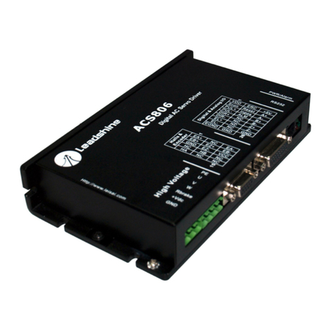
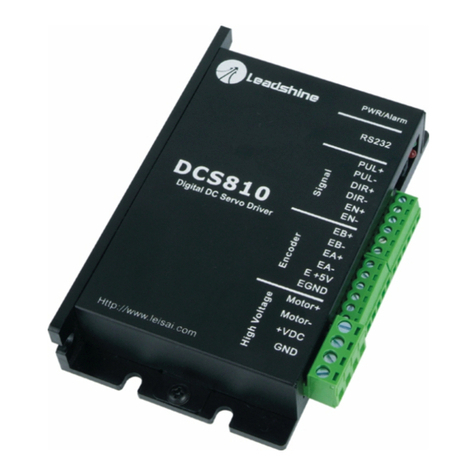
Leadshine Technology DCS810S User manual

User sManual
For
DCS810S
DigitalDC ServoDriver
Revision 1.0
2009All RightsReserved
Attention:Pleaseread thismanual carefullybeforeusingthe driver!
3/F, Block 2, NanyouTiananIndustrialPark, NanshanDist, Shenzhen, China
Tel: (86)755-26434369 Fax: (86)755-26402718
URL: www.leadshine.com E-Mail: sales@leadshine.com
Thecontentinthismanualhasbeencarefullypreparedandisbelievedtobeaccurate,
butnoresponsibilityisassumedforinaccuracies.
Leadshinereservestherighttomakechangeswithoutfurthernotice toanyproducts
hereintoimprovereliability,functionordesign.Leadshinedoesnotassumeany
liabilityarisingoutoftheapplicationoruseofanyproductorcircuitdescribed
herein;neitherdoesit conveyanylicenseunderitspatentrightsofothers.
Leadshine sgeneralpolicydoesnotrecommendtheuseofitsproductsinlife
supportoraircraftapplicationswhereinafailureormalfunction oftheproductmay
directlythreatenlifeorinjury.AccordingtoLeadshine stermsandconditionsof
sales,theuserofLeadshine sproductsinlifesupportoraircraftapplications
assumesall risksofsuchuseandindemnifiesLeadshineagainstall damages.
©2009byLeadshineTechnologyCompanyLimited.
AllRightsReserved

Contents
Tel: (86)755-26434369IWebsite: www.leadshine.com
TableofContents
1. Introduction, FeaturesandApplications..................................................................1
Introduction..........................................................................................................1
Features................................................................................................................1
Applications.........................................................................................................2
2. SpecificationsandOperating Environment.............................................................2
ElectricalSpecifications.......................................................................................2
MechanicalSpecifications....................................................................................3
EliminationofHeat..............................................................................................3
OperatingEnvironmentandParameters...............................................................3
3. Connections.............................................................................................................4
ConnectorConfiguration......................................................................................4
Generalinformation....................................................................................4
Moreabout+5V, PUL, DIR, ERR/RESSignals..........................................5
DIPSwitchSW1, SW2................................................................................5
ControlSignalConnections..................................................................................6
EncoderConnections............................................................................................6
RS232 Interface Connection.................................................................................7
TypicalConnections.............................................................................................7
4. ServoSetup.............................................................................................................8
Install Encoder......................................................................................................8
PreparePowerSupply..........................................................................................9
RegulatedorUnregulatedPowerSupply....................................................9
SelectingSupplyVoltage.............................................................................9
PrepareController................................................................................................9
SystemConnectionsandNoisePrevention........................................................10
WireGauge................................................................................................10
Contents
Tel: (86)755-26434369II Website: www.leadshine.com
CableRouting...........................................................................................10
Twisted Wires............................................................................................10
CableShielding.........................................................................................11
SystemGrounding.....................................................................................11
PowerSupplyConnection.........................................................................11
5. TuningtheServo...................................................................................................12
TestingtheServo................................................................................................12
TuningtheServo................................................................................................13
6. UsingTips.............................................................................................................15
SequenceChartofControlSignals....................................................................15
ProtectionFunctions...........................................................................................15
Over-currentProtection.............................................................................16
Over-voltageProtection............................................................................16
Under-voltageProtection..........................................................................16
PhaseErrorProtection...............................................................................16
EncoderErrorProtection...........................................................................16
Position FollowingErrorProtection.........................................................16
ProtectionIndications................................................................................17
ChangingDefault MotorDirection....................................................................17
MaximumPulseInputFrequency......................................................................17
APPENDIX...............................................................................................................19
TWELVEMONTHLIMITEDWARRANTY...................................................19
EXCLUSIONS...................................................................................................19
OBTAINING WARRANTYSERVICE.............................................................19
WARRANTYLIMITATIONS...........................................................................19
SHIPPING FAILEDPRODUCT.......................................................................20

D
DC
CS
S8
81
10
0S
S
D
Di
ig
gi
it
ta
al
l
D
DC
C
S
Se
er
rv
vo
o
D
Dr
ri
iv
ve
er
r
M
Ma
an
nu
ua
al
l
R
Re
ev
v1
1.
.0
0
Tel: (86)755-264343691Website: www.leadshine.com
1. Introduction, Features and Applications
Introduction
TheDCS810SisadigitalDCservo driverdevelopedwithDSPandhighefficient
MOSFETtechnologies.Inposition control,it seasyfortheenduserstochange
steppingdriverstotheDCS810Swithoutchangingcontrolsystems,becauseits
inputcommandisPUL/DIRsignal,whichiscompatiblewiththatofstepping
drivers.Inlowpowermotion controlapplications,performancesofDCservo
systemsusingtheDCS810SarebetterthanthoseofdigitalACservo systemsin
velocity,precision,stability,oratleastasgood asthoseofdigitalACservosystems.
However,thecostoftheDCS810Sstaysatthepricelineofsteppingdriver,namely
farlowerthanthoseofACservodrivers.
ComparedtotheDCS810, theDCS810Sacceptssingle-endedencodersignalswhile
theDCS810 acceptsdifferentialencodersignals.
TheDCS810Sisveryeasytotuneandall parametersarevisible.PCbasedand
handheldconfiguration&tuningtools,includingProTuner(Windowsbasedsetup
software)and STU(Small servotuningunit)canmeetdifferenttuningenvironments
orrequirements.
Features
l18-80VDC, 0-20A, 20-400W.
lBasedonDSPcontroltechnologyand highsmoothservocontrolalgorithm.
lPCbasedandhandheldconfigurationtools, includingProTunerandSTU.
lFeedbackresolution ×4 encoderlinecount.
lPosition Followingerrorlockrangeadjustable
lElectronicgearratiofrom1/255 to255
lBuilt-inmotioncontrollerforself-testwithtrapezoidalvelocityprofile
lSupportPUL/DIRandCW/CCWcontrolsignals
D
DC
CS
S8
81
10
0S
S
D
Di
ig
gi
it
ta
al
l
D
DC
C
S
Se
er
rv
vo
o
D
Dr
ri
iv
ve
er
r
M
Ma
an
nu
ua
al
l
R
Re
ev
v1
1.
.0
0
Tel: (86)755-264343692Website: www.leadshine.com
lOpto-isolatedinputs, supportsingle-endedsignals
l10 latesterrorsself-recordfunction
lOver-current,over-voltage,under-voltage,phaseerror,encodererror,position
followingerrorprotections
lSmall size, surface-mounttechnology
Applications
Suitableforawiderangeofequipmentsand instrumentssuchasinkjetprinters,mini
typeengravingmachines,andetc.Itperformsbetterinapplicationsrequirelow
noise,highvelocity,highprecisionandhighreliability.
2. Specifications andOperatingEnvironment
ElectricalSpecifications(Tj =25oC/77oF)
DCS810S
Parameters Min. Typical Max. Unit
Peakoutputcurrent 0 - 20 A
Supplyvoltage +18 - +80 VDC
Logicsignalcurrent 7 10 15 mA
Pulseinputfrequency 0 - 200 kHz
Isolationresistance 500 MΩ
Currentprovidedtoencoder 50 mA

D
DC
CS
S8
81
10
0S
S
D
Di
ig
gi
it
ta
al
l
D
DC
C
S
Se
er
rv
vo
o
D
Dr
ri
iv
ve
er
r
M
Ma
an
nu
ua
al
l
R
Re
ev
v1
1.
.0
0
Tel: (86)755-264343693Website: www.leadshine.com
MechanicalSpecifications (unit:mm[inch])
Figure1:Mechanicalspecifications
EliminationofHeat
lDriver sreliableworkingtemperatureshouldbe<70 (158 ),and motor
workingtemperatureshouldbe<80 (176 );
lItisrecommendedtomountthedriververticallytomaximizeheatsinkarea.
OperatingEnvironmentand Parameters
Cooling Natural coolingorforcedcooling
Environment Avoiddust, oil fog andcorrosivegases
AmbientTemperature
0℃-50℃(32 -122 )
Humidity 40 –95%RH
OperatingEnvironment
Vibration 5.9m/s2Max
StorageTemperature -20℃-65℃(-4 -149 )
Weight Approx. 210g(7.4oz)
D
DC
CS
S8
81
10
0S
S
D
Di
ig
gi
it
ta
al
l
D
DC
C
S
Se
er
rv
vo
o
D
Dr
ri
iv
ve
er
r
M
Ma
an
nu
ua
al
l
R
Re
ev
v1
1.
.0
0
Tel: (86)755-264343694Website: www.leadshine.com
3. Connections
ConnectorConfiguration
Generalinformation
Control SignalConnector
Pin Signal Description I/O
1 +5V Common +5Vpowerinput. I
2 PUL Pulsecontrolsignal.See moreinformation aboutPULin “More
about+5V, PUL, DIR, ERR/RESSignals”section. I
3 DIR Direction controlsignal.See moreinformationaboutDIRin “More
about+5V, PUL, DIR, ERR/RESSignals”section. I
EncoderSignalConnector
Pin Signal Description I/O
1 EB EncoderchannelB input. I
2 EA EncoderchannelAinput. I
3 E+5V Positive pole ofthe auxiliarypowersupply(50 mA(Max)). O
4 EGND Groundofthe auxiliarypowersupply. GND
5 ERR/RES Alarmsignaloutput(+5V)orrestartsignalinput(+5V). O
PowerConnector
Pin Signal Description I/O
1 Motor+ Motorpositive connection. O
2 Motor- Motornegative connection. O
3 +VDC +18 TO80VDCpowerinput. I
4 GND Powerground. GND
RS232 CommunicationConnector
Pin Signal Description I/O
1 NC Notconnected. -
2 +5V +5VpoweronlyforSTU. O
3 TxD RS232 transmit. O
4 GND Ground. GND
5 RxD RS232 receive. I
6 NC Notconnected. -

D
DC
CS
S8
81
10
0S
S
D
Di
ig
gi
it
ta
al
l
D
DC
C
S
Se
er
rv
vo
o
D
Dr
ri
iv
ve
er
r
M
Ma
an
nu
ua
al
l
R
Re
ev
v1
1.
.0
0
Tel: (86)755-264343695Website: www.leadshine.com
Moreabout+5V, PUL, DIR, ERR/RESSignals
PinFunction Details
+5V +5VOpto-couplerpowersupply.
PUL
Pulsesignal: Insinglepulse(pulse/direction)mode,thisinputrepresents
pulsesignal, eachrisingorfallingedgeactive(softwareconfigurable);4-5V
whenPUL-HIGH,0-0.5VwhenPUL-LOW.Indoublepulsemode
(pulse/pulse),thisinputrepresentsclockwise(CW)pulse,activebothathigh
levelandlowlevel(fixedlevelsoftwareconfigurable).Forreliableresponse,
pulsewidthshouldbelongerthan2.5μs.Seriesconnectresistorsfor
current-limitingwhen+12Vor+24Vused.ThesameasDIRand ENA
signals.
DIR
DIRsignal: Insingle-pulsemode,thissignalhaslow/high voltagelevels,
representingtwodirectionsofmotorrotation;indouble-pulsemode
(softwareconfigurable),thissignaliscounter-clock(CCW)pulse,active
bothathighlevelandlowlevel(fixedlevelsoftwareconfigurable).For
reliablemotionresponse,DIRsignalshouldbeaheadofPULsignalby5μs
atleast. 4-5VwhenDIR-HIGH,0-0.5VwhenDIR-LOW.Pleasenotethat
rotationdirection isalsorelatedtomotor-driverwiringmatch.Exchanging
theconnectionsoftwowiresofthemotortothedriverand A/Bphasesignals
ofencoderwill reversemotiondirection.
ERR/RES
ERR/RESPin: UsedtooutputerrorandresettheDCS810Stoclearerrors.
+5VDCwhendriverisnormal.Ifprotectionfunctionssuchasover-voltage,
over-current, phaseerror,encodererror,position followingerrorare
activated,ERR/RESpinwill bepulledtoLOWlevel (EGND). Only Position
FollowingErrorcanbeclearedbyconnectingtheE+5VtoERR/RES,and
theusersshouldrepowerthedrivertoclearothererrorsafterremovingother
relatedproblem(s).
DIPSwitchSW1, SW2
TherearetwoDIPswitches(SW1andSW2)canbeusedtoselect4group servo
parametersstoredinEEPROMofthedriver.Theusercanselectonegroupofthese
servoparameterstooptimizetheperformancefordifferentapplications,inwhich
usingdifferentmotorsorhavingdifferentload.Formostapplications,thesetwoDIP
switchesshouldbebothonOFF position (FactoryDefault Status),saving/selecting
D
DC
CS
S8
81
10
0S
S
D
Di
ig
gi
it
ta
al
l
D
DC
C
S
Se
er
rv
vo
o
D
Dr
ri
iv
ve
er
r
M
Ma
an
nu
ua
al
l
R
Re
ev
v1
1.
.0
0
Tel: (86)755-264343696Website: www.leadshine.com
theuser sownservoparameters, NOTother3 group fordedicatedapplications.
ControlSignalConnections
TheDCS810Shas2opticallyisolatedlogicinputstoacceptPUL/DIRcontrol
signals.Theseinputsareisolatedtominimizeoreliminateelectricalnoisescoupled
ontothecontrolsignals.Inthefollowingfigure,connectionstoopen-collector
controlsignalsareillustrated.
Figure2:Connectionstoopen-collectorcontrolsignal(common-anode)
EncoderConnections
TheDCS810Scanacceptencoderinputfromsingle-endedincrementalencoders.
Notethattwisted-pairshieldedcablingprovidesthebestimmunityinelectrically
noisyenvironments.
If theencoderdrainslessthan50mA, theDCS810Scansupplytheencoderdirectly,
and connectit asFigure3. Iftheencoderdrainsmorethan50mA,useanexternal
DCsupplyand connectitasFigure4.

D
DC
CS
S8
81
10
0S
S
D
Di
ig
gi
it
ta
al
l
D
DC
C
S
Se
er
rv
vo
o
D
Dr
ri
iv
ve
er
r
M
Ma
an
nu
ua
al
l
R
Re
ev
v1
1.
.0
0
Tel: (86)755-264343697Website: www.leadshine.com
Figure3:TheDCS810Ssuppliesthesingle-endedencoderdirectly
Figure4:Usingexternal DCpowersupplytosupplytheencoder
RS232 Interface Connection
Figure5:RS232interfaceconnection
TypicalConnections
TwotypicalconnectionsoftheDCS810SareshownasFigure6. Pleaseconsult
“ControlSignalConnections”and “EncoderConnections”formoreinformation
aboutcontrollerand encoderconnections.
D
DC
CS
S8
81
10
0S
S
D
Di
ig
gi
it
ta
al
l
D
DC
C
S
Se
er
rv
vo
o
D
Dr
ri
iv
ve
er
r
M
Ma
an
nu
ua
al
l
R
Re
ev
v1
1.
.0
0
Tel: (86)755-264343698Website: www.leadshine.com
Figure6:Typical connection(Open-collectorcontrolsignalandsingle-endedencoder.)
4. ServoSetup
Beforeyoustarttheservo,youcanfollowthebelowsteps.
InstallEncoder
If yourmotorhasnoencoder,youmusthaveanencoder(morethan200 lines)
properlymountedonthemotorbeforeyou start.Andpleaseassembletheencoder
according toitsfactorymanual.Pleaseuseshieldedcablesand separateencoder
signalcablefrominterferencesources,suchasmotorwiresandpowerwiresatleast
5 cm.

D
DC
CS
S8
81
10
0S
S
D
Di
ig
gi
it
ta
al
l
D
DC
C
S
Se
er
rv
vo
o
D
Dr
ri
iv
ve
er
r
M
Ma
an
nu
ua
al
l
R
Re
ev
v1
1.
.0
0
Tel: (86)755-264343699Website: www.leadshine.com
PreparePowerSupply
RegulatedorUnregulatedPower Supply
Bothregulatedandunregulatedpowersuppliescanbeusedtosupplythedriver.
However,unregulatedpowersuppliesarepreferredduetotheirabilitytowithstand
currentsurge.Ifregulatedpowersupplies(suchasmostswitchingsupplies.)are
indeedused,it isimportanttohavelargecurrentoutputrating toavoidproblems
likecurrentclamp,forexampleusing4Asupplyfor3Amotor-driveroperation.On
theotherhand,ifunregulatedsupplyisused,onemayuseapowersupplyoflower
currentratingthanthatofmotor(typically50%~70%ofmotorcurrent). Thereason
isthatthedriverdrawscurrentfromthepowersupplycapacitoroftheunregulated
supplyonlyduringtheON durationofthePWMcycle,butnotduringtheOFF
duration.Therefore,theaveragecurrentwithdrawnfrompowersupplyis
considerablylessthanmotorcurrent.Forexample,two3Amotorscanbewell
suppliedbyonepowersupplyof4Arating.
Selecting Supply Voltage
TheDCS810Scanactuallyoperatewithin+18Vto+80VDC,including powerinput
fluctuation and backEMFvoltagegeneratedbymotorcoilsduring motorshaft
deceleration.Theratedvoltageofthemotorisanimportantparameterwhen
selecting supplyvoltage.Generallyspeaking,do notuseapowersupplyvoltage
morethan5voltsoftheratedvoltageofthemotor.Highervoltagemaycausebigger
motorvibrationatlowerspeed,andit mayalsocauseover-voltageprotectionor
evendriverdamage.
PrepareController
Prepareacontrollerwithpulseanddirectionsignals.However,theDCS810Shasa
built-inmotioncontrollerforself-testandServoTuning.Thebuilt-inmotion
controllercangeneratecontrolsignalwithtrapezoidalvelocityprofile.
D
DC
CS
S8
81
10
0S
S
D
Di
ig
gi
it
ta
al
l
D
DC
C
S
Se
er
rv
vo
o
D
Dr
ri
iv
ve
er
r
M
Ma
an
nu
ua
al
l
R
Re
ev
v1
1.
.0
0
Tel: (86)755-2643436910 Website: www.leadshine.com
SystemConnectionsand NoisePrevention
Afterfinishingtheabovesteps,youcanconnectyourservosystem. Beforeyoustart,
makesurethatthepowerisoff.Connectyoursystemaccordingtoconnection
diagramsbefore, andpayattentiontothefollowing tipswhenwiring.
Wire Gauge
Thesmallerwirediameter(lowergauge),thehigherimpedance.Higherimpedance
wirewillbroadcastmorenoisethanlowerimpedance wire.Therefore,when
selectingthewiregauge,itispreferabletoselectlowergauge(i.e.largerdiameter)
wire.Thisrecommendationbecomesmorecriticalasthecablelengthincreases.Use
thefollowing tabletoselecttheappropriatewiresizetouseinyourapplication.
Current(A) Minimumwiresize(AWG)
10 #20
15 #18
20 #16
CableRouting
All contentsensitivesignalwiresshouldberoutedasfarawayfrommotorpower
wiresanddriverpowerwiresaspossible.Motorpowerand driverpowerwiresare
majorsourcesofnoiseandcaneasilycorruptanearbysignal.Thisissuebecomes
increasinglyimportantwithlongermotorpoweranddriverpowerwireslengths.
TwistedWires
Twistedwireseffectivelyincreasingnoiseimmunity.Thesuccessivetwistseliminate
noisetransientsalongthelengthofthecable.Bothsignalcablesandpowercables
shouldbeofthetwistedandshieldedtype.Differentialsignalwiresshouldbe
twistedasapair.Thecombinationoftwistedpairwiresandadifferentialsignal
significantlyaddstonoiseimmunity.Powerwiresshouldbetwistedasagroup

D
DC
CS
S8
81
10
0S
S
D
Di
ig
gi
it
ta
al
l
D
DC
C
S
Se
er
rv
vo
o
D
Dr
ri
iv
ve
er
r
M
Ma
an
nu
ua
al
l
R
Re
ev
v1
1.
.0
0
Tel: (86)755-2643436911 Website: www.leadshine.com
alongwiththeground(orchassis)wire, ifavailable.
CableShielding
All signalwiresshouldbebundledandshieldedseparatelyfromdriverpowerand
motorpowerwires.Powerwiresshouldalsobebundledand shielded.When
groundingashield,therule-of-thumbistodosoatthe ‘source ofpowerwhile
leavingtheothershieldendopen.Forexample,inthecaseofmotorpowerwires,
thiswouldbethedriveside.Ideally,twistedpairsshouldbeindividuallyshielded
andisolatedfromtheoutershield,whichencompassesall wireswithinthecable.
However,since thistypeofstringentshieldingpracticeisoftennotrequired,typical
cablesdonotprovideisolationbetweeninnerandoutershields.
SystemGrounding
Goodgroundingpracticeshelpreduce themajorityofnoisepresentinasystem.All
common groundswithinanisolatedsystemshouldbetiedtoPE(protectiveearth)
througha ‘SINGLE lowresistance point.AvoidingrepetitivelinkstoPEcreating
groundloops,whichareafrequentsource ofnoise.Centralpointgroundingshould
alsobeappliedtocableshielding;shieldsshouldbeopenononeendandgrounded
ontheother.Closeattentionshouldalsobegiventochassiswires.Forexample,
motorsaretypicallysuppliedwithachassiswire.Ifthischassiswireisconnectedto
PE,butthemotorchassisitselfisattachedtothemachineframe,whichisalso
connectedtoPE,agroundloopwillbecreated.Wiresusedforgroundingshouldbe
ofaheavygaugeandasshortaspossible.Unusedwiringshouldalsobegrounded
whensafetodososincewiresleftfloatingcanactaslargeantennas,which
contributetoEMI.
Power Supply Connection
NEVER connectpowerandgroundinthewrongdirection,becauseit will damage
theDCS810Sdriver.ThedistancebetweentheDCpowersupplyofthedriveand
D
DC
CS
S8
81
10
0S
S
D
Di
ig
gi
it
ta
al
l
D
DC
C
S
Se
er
rv
vo
o
D
Dr
ri
iv
ve
er
r
M
Ma
an
nu
ua
al
l
R
Re
ev
v1
1.
.0
0
Tel: (86)755-2643436912 Website: www.leadshine.com
thedriveitselfshouldbeasshortaspossiblesincethecablebetweenthetwoisa
sourceofnoise.Whenthepowersupplylinesarelongerthan50 cm,a
1000µF/100Velectrolyticcapacitorshouldbeconnectedbetweentheterminal
“GND”and theterminal “+VDC”.Thiscapacitorstabilizesthevoltagesuppliedto
thedriveaswell asfiltersnoiseonthepowersupplyline. Pleasenotethatthe
polaritycannotbereversed.
Itisrecommended tohavemultipledriversto shareonepowersupply toreducecost
ifthesupplyhasenoughcapacity. Toavoidcross interference, DONOT daisy-chain
thepowersupplyinputpinsofthedrivers.Instead,pleaseconnectthemtopower
supplyseparately.
5.TuningtheServo
TestingtheServo
You maywishtosecurethemotorsoit can tjumpoff thebench.Turnonthepower
supply,thegreen(Power) LEDwill light.TheDCS810Shasdefaultparameters
storedinthedriver.If thesystemhasnohardwareand wiringsproblem,themotor
shouldbelockedandthedrivershouldbeready.
If themotorjumpsslightlyandtheredLEDimmediatelyturnson(flickers),then
eitherthemotorortheencoderiswiredinreversal.Openthetuningsoftware
ProTunerand checkdriverstatusbyclicking Err_check.If it s PhaseError,then
reversalmotorwiresorexchangeencoderinputsandtryagain.If it s Encoder
Error,pleasecheckencoderanditswirings,andthentryagain.If it still doesn t
workafteryoufollowedall oftheprevioussteps,pleasecontactusat
tech@leadshine.com.
If theredLEDisoffandthemotorisnormal,thenyoucanstarttotunetheservo
withselectedtool. ProTuner and STU areavailablefortheDCS810S.

D
DC
CS
S8
81
10
0S
S
D
Di
ig
gi
it
ta
al
l
D
DC
C
S
Se
er
rv
vo
o
D
Dr
ri
iv
ve
er
r
M
Ma
an
nu
ua
al
l
R
Re
ev
v1
1.
.0
0
Tel: (86)755-2643436913 Website: www.leadshine.com
TuningtheServo
Aservosystemiserror-driven.The “Gain”ofthesystemdetermineshowhardthe
servotriestoreducetheerror.Ahigh-gainsystemcanproducelargecorrecting
torqueswhentheerrorisverysmall.Ahighgainisrequirediftheoutputisrequired
tofollowtheinputfaithfullywithminimalerror.
Aservo motoranditsloadbothhaveinertia,whichtheservoamplifiermust
accelerateanddeceleratewhileattemptingtofollowachangeattheinput.The
presence oftheinertiawill tendtoresult inover-correction,withthesystem
oscillatingbeyondeithersideofitstarget.It scalledUNDERDAMPEDstatus.See
Figure13. Thisoscillationmustbedamped,buttoomuchdamping willcausethe
responsetobesluggish,namelycausethesystemtogetintoanOVERDAMPED
state.Whenwetuneaservo,wearetryingtoachievethefastestresponsewithlittle
ornoovershoot, namelygetaCRITICALLYDAMPEDresponse.
Figure13:Stepandimpulseresponses
Asmentionedinpreviouscontents,theDCS810Sisadigitalservo driverandits
inputcommandisPUL/DIRsignal.Inotherwords,stepresponsejustexistsineach
D
DC
CS
S8
81
10
0S
S
D
Di
ig
gi
it
ta
al
l
D
DC
C
S
Se
er
rv
vo
o
D
Dr
ri
iv
ve
er
r
M
Ma
an
nu
ua
al
l
R
Re
ev
v1
1.
.0
0
Tel: (86)755-2643436914 Website: www.leadshine.com
stepcommandsignal.Foreachstepcommandsignalisaverysmallmovement,so
OVERSHOOTandSETTLING TIMEbetweeneachstepareverysmall,causing
youhardlycanseeastepresponsesuchasFigure13, eveniftheSETPOINTisa
verylargequantityandtheaccelerationisveryhigh.
However,ifyoutrytoevaluateperformancesofthedigitalservobyinvestigatingits
positiontracking-errororpositionfollowingerror,youmayfindit smucheasier
thaninvestigatingitsstepresponse.Theeasiestwaytogetatracking-erroror
positionfollowingerrorresponseistoinduce animpulseloadonthemotor.See
Figure13 at “time20”.
LeadshineofferaWindowsbasedsetupsoftware ProTuner toitscustomersfor
evaluatingservoperformances.Small servotuningunit STU (optional)isavailable
too, andit sforfieldtuningwithoutPC.
TuningservosystemsformedbytheDCS810Sdriverscanbesummarizedasthe
followingrules:
1. If servosystemisUNSTABLE,thenthefirstthingoftuningistostabilize
thesystem.Youcanincrease DerivativeGain of PositionLoop (Kd)or
decrease ProportionalGain ofPositionLoop(Kp)or IntegralGain of
Position Loop(Ki).
2. If servosystemisUNDERDAMPED,thenincreaseKdordecreaseKpor
Ki.
3. If servo systemisCRITICALLYDAMPED,thenstoptuningand
downloadtheparametersettingstothedriver sEEPROM.
4. If servosystemisOVERDAMPED,thendecreaseKdorincreaseKpor
Ki.
Pleasesee User’sManualforTuningtheDCS810SwithProTuner”formore
detail aboutServoTuning.

D
DC
CS
S8
81
10
0S
S
D
Di
ig
gi
it
ta
al
l
D
DC
C
S
Se
er
rv
vo
o
D
Dr
ri
iv
ve
er
r
M
Ma
an
nu
ua
al
l
R
Re
ev
v1
1.
.0
0
Tel: (86)755-2643436915 Website: www.leadshine.com
6. UsingTips
Sequence ChartofControlSignals
Inordertoavoidsomefault operationsanddeviations,PUL,DIRandENshould
abidebysomerules, shownasthefollowingfigure:
Figure14:Sequence chart ofcontrolsignals
Notes:
a) t1:ENmustbeaheadofDIRbyatleast5µs.Usually, EN+ and EN-areNC
(notconnected). See Connections sectionformoreinformation.
b) t2:DIRmustbeaheadofPULeffectiveedgebyatleast5 µstoensure
correctdirection.
c) t3:Pulsewidthnotless than2.5 µs;
d) t4:Lowlevelwidthnotless than2.5 µs.
ProtectionFunctions
Toimprovereliability,thedriverincorporatessomebuilt-inprotectionfunctions.
TheDCS810SusesoneREDLEDtoindicatewhatprotectionhasbeenactivated.
TheperiodictimeofREDis5s(seconds),andhowmanytimestheREDturnson
indicateswhatprotectionhasbeenactivated.Becauseonlyoneprotectioncanbe
displayedbyREDLED,sothedriverwill decidewhaterrortodisplayaccordingto
D
DC
CS
S8
81
10
0S
S
D
Di
ig
gi
it
ta
al
l
D
DC
C
S
Se
er
rv
vo
o
D
Dr
ri
iv
ve
er
r
M
Ma
an
nu
ua
al
l
R
Re
ev
v1
1.
.0
0
Tel: (86)755-2643436916 Website: www.leadshine.com
theirpriorities.See thefollowing ProtectionIndications tablefordisplaying
priorities.
Over-currentProtection
Protectionwillbeactivatedwhencontinuouscurrentexceeds20A,andREDLED
will turnononcewithineachperiodictime(5 s).
Over-voltageProtection
Whenpowersupplyvoltageexceeds85±1.5 VDC,protectionwill beactivatedand
REDLEDwill turnontwice withineachperiodictime(5 s).
Under-voltageProtection
Whenpowersupplyvoltageislowerthan16.5±1.5 VDC,protection willbe
activatedandREDLEDwill turnon threetimeswithineachperiodictime(5 s).
PhaseErrorProtection
Motorpowerlineswrong ¬connectedand encoderfeedbacksignalsA/Bphases
wrongconnectedwill activatethisprotection.REDLEDwill turnonfourtimes
withineachperiodictime(5 s).
Encoder ErrorProtection
Noencoderfeedbacksignalsorwrongencoderfeedbacksignalswill activatethis
protection. REDLEDwillturnonfivetimeswithineachperiodictime(5 s).
PositionFollowing ErrorProtection
WhenpositionfollowingerrorreachesPositionFollowingErrorLimitparameter
settinginthedriver,thisprotectionwillbeactivated.REDLEDwill turnonseven
timeswithineachperiodictime(5 s).

D
DC
CS
S8
81
10
0S
S
D
Di
ig
gi
it
ta
al
l
D
DC
C
S
Se
er
rv
vo
o
D
Dr
ri
iv
ve
er
r
M
Ma
an
nu
ua
al
l
R
Re
ev
v1
1.
.0
0
Tel: (86)755-2643436917 Website: www.leadshine.com
Attention: Whenaboveprotectionsareactive,themotorshaftwillbefreeorthe
LEDwill turnred.Resetthedriverby repoweringit (ERR/RESsignalonlycanbe
usedtoclear “Position FollowingErrorProtection”error.)tomakeit function
properlyafterremoving aboveproblems.Sincethereisnoprotectionagainstpower
leads(﹢,﹣)reversal,it iscriticaltomakesurethatpowersupplyleadscorrectly
connectedtodriver. Otherwise, thedriverwillbedamagedinstantly.
ProtectionIndications
Priority
Time(s)ofON Sequence wave ofREDLED Description
1st 1 Over-currentprotection
2nd 2
Over-voltageprotection
3rd 3 Under-voltage protection
4th 4 Phase errorprotection
5th 5 Encodererrorprotection
6th 7 Position followingerror
protection
ChangingDefaultMotorDirection
TheDCS810SwillturnthemotorintheCWdirectionwhenthedirectioninputis
“high”(logical “1”). If insteadCCWispreferred, then:
1)Reversethe “motor+”and “motor-”leads.
2)Reversetheencoder “ChannelA”and “ChannelB”leads.
MaximumPulseInputFrequency
MaximumPulseInputFrequencyisthehighestfrequencythatthedrivercanaccept.
ToconvertthisfrequencytoRPM,usethefollowingformula:
D
D
C
C
S
S
8
8
1
1
0
0
S
S
D
D
i
i
g
g
i
i
t
t
a
a
l
l
D
D
C
C
S
S
e
e
r
r
v
v
o
o
D
D
r
r
i
i
v
v
e
e
r
r
M
M
a
a
n
n
u
u
a
a
l
l
R
R
e
e
v
v
1
1
.
.
0
0
Tel: (86)755-2643436918 Website: www.leadshine.com
atordenoCAM numeratorCAM
CountLineEncoder
FrequenceInputPulseMax
RPM min__
4)(
60)(
(max) ×
×
×
=

D
DC
CS
S8
81
10
0S
S
D
Di
ig
gi
it
ta
al
l
D
DC
C
S
Se
er
rv
vo
o
D
Dr
ri
iv
ve
er
r
M
Ma
an
nu
ua
al
l
R
Re
ev
v1
1.
.0
0
Tel: (86)755-2643436919 Website: www.leadshine.com
APPENDIX
TWELVEMONTHLIMITEDWARRANTY
LeadshineTechnologyCo., Ltd.warrantsitsproductsagainstdefectsinmaterials
and workmanshipforaperiodof12 monthsfromshippingdate. Duringthewarranty
period,Leadshinewilleither,atitsoption,repairorreplace productswhichproved
tobedefective.
EXCLUSIONS
Theabovewarrantyshall notapplytodefectsresultingfrom:improperor
inadequatehandlingbycustomer;improperorinadequatecustomerwiring;
unauthorizedmodificationormisuse;oroperationbeyondtheelectrical
specificationsoftheproductand/oroperationbeyondenvironmentalspecifications
fortheproduct.
OBTAININGWARRANTYSERVICE
Toobtainwarrantyservice,areturnedmaterialauthorization number(RMA)must
beobtainedfromcustomerserviceate-mail: tech@leadshine.com beforereturning
productforservice.Customershall prepayshippingchargesforproductsreturnedto
Leadshineforwarrantyservice,andLeadshineshall payforreturnofproductsto
customer.
WARRANTYLIMITATIONS
Leadshinemakesnootherwarranty,eitherexpressedorimplied,withrespecttothe
product.Leadshinespecificallydisclaimstheimpliedwarrantiesofmerchantability
and fitness foraparticularpurpose.Somejurisdictionsdonotallowlimitationson
howlongandimpliedwarrantylasts,sotheabovelimitation orexclusionmaynot
applytoyou.However,anyimpliedwarrantyofmerchantabilityorfitness islimited
D
DC
CS
S8
81
10
0S
S
D
Di
ig
gi
it
ta
al
l
D
DC
C
S
Se
er
rv
vo
o
D
Dr
ri
iv
ve
er
r
M
Ma
an
nu
ua
al
l
R
Re
ev
v1
1.
.0
0
Tel: (86)755-2643436920 Website: www.leadshine.com
tothe12-monthdurationofthiswrittenwarranty.
SHIPPINGFAILEDPRODUCT
If yourproductshouldfail duringthewarrantyperiod,e-mail customerserviceat
tech@leadshine.com toobtainareturnedmaterialauthorizationnumber(RMA)
beforereturningproductforservice.Pleaseincludeawrittendescriptionofthe
problemalongwithcontactnameandaddress.Sendfailedproducttodistributorin
yourareaor:LeadshineTechnologyCo., Ltd.3/F,Block2, TiananIndustrialPark,
NanshanDist,Shenzhen,China.Alsoencloseinformationregardingthe
circumstancespriortoproductfailure.
Table of contents
Other Leadshine Technology Servo Drive manuals

Leadshine Technology
Leadshine Technology ACS306 User manual

Leadshine Technology
Leadshine Technology DB810A User manual

Leadshine Technology
Leadshine Technology Vector Easy H2-506 User manual

Leadshine Technology
Leadshine Technology M760 User manual

Leadshine Technology
Leadshine Technology ACS806 User manual

Leadshine Technology
Leadshine Technology DCS810 User manual
Popular Servo Drive manuals by other brands

Emheater
Emheater EM12-Z Series user manual

Beckhoff
Beckhoff AX8000 System manual

SMC Networks
SMC Networks LESYH Series Operation manual

Danaher Motion
Danaher Motion SERVOSTAR S600 manual

Applied Motion Products
Applied Motion Products BLuAC5-S Hardware manual

Allen-Bradley
Allen-Bradley Kinetix 5700 user manual