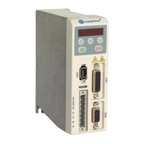
Leadshine Technology ACS806 User manual

User sManual
For
ACS806
DigitalAC ServoDrive
Revision 1.0
2009All RightsReserved
Attention:Pleaseread thismanual carefullybeforeusingthe drive!
3/F, Block 2, NanyouTiananIndustrialPark, NanshanDist, Shenzhen, China
Tel: (86)755-26434369 Fax: (86)755-26402718
URL: www.leadshine.com E-Mail: sales@leadshine.com
Thecontentinthismanualhasbeencarefullypreparedandisbelievedtobeaccurate,
butnoresponsibilityisassumedforinaccuracies.
Leadshinereservestherighttomakechangeswithoutfurthernotice toanyproducts
hereintoimprovereliability,functionordesign.Leadshinedoesnotassumeany
liabilityarisingoutoftheapplicationoruseofanyproductorcircuitdescribed
herein;neitherdoesit conveyanylicenseunderitspatentrightsofothers.
Leadshine sgeneralpolicydoesnotrecommendtheuseofitsproductsinlife
supportoraircraftapplicationswhereinafailureormalfunction oftheproductmay
directlythreatenlifeorinjury.AccordingtoLeadshine stermsandconditionsof
sales,theuserofLeadshine sproductsinlifesupportoraircraftapplications
assumesall risksofsuchuseandindemnifiesLeadshineagainstall damages.
©2009byLeadshineTechnologyCompanyLimited.
AllRightsReserved

Contents
Tel: (86)755-26434369IWebsite: www.leadshine.com
TableofContents
1. Introduction, FeaturesandApplications...................................................................1
Introduction...........................................................................................................1
Features.................................................................................................................1
Applications..........................................................................................................2
2. SpecificationsandOperating Environment..............................................................2
ElectricalSpecifications........................................................................................2
Performance Specifications...................................................................................2
MechanicalSpecifications.....................................................................................3
EliminationofHeat...............................................................................................3
OperatingEnvironmentandParameters................................................................3
3. Connections..............................................................................................................4
ConnectorConfiguration.......................................................................................4
GeneralInformation.....................................................................................4
MoreaboutI/OSignals................................................................................6
ENA, PUL, DIRInputCircuitsand Connections..................................................7
RL, FLInputCircuitsandConnections.................................................................8
Pend,ALMOutputCircuitsandConnections.......................................................9
A+,A-, B+, B-, Z+, Z-OutputCircuit..................................................................9
EncoderandHall SensorConnections................................................................10
RS232 Interface Connection................................................................................11
TypicalConnections............................................................................................11
4. ServoSetup............................................................................................................13
Install EncoderandHall sensor...........................................................................13
PreparePowerSupply.........................................................................................13
RegulatedorUnregulatedPowerSupply...................................................13
SelectingSupplyVoltage............................................................................14
PrepareController...............................................................................................14
Contents
Tel: (86)755-26434369II Website: www.leadshine.com
SystemConnectionsandNoisePrevention.........................................................14
WireGauge.................................................................................................14
CableRouting.............................................................................................15
Twisted Wires.............................................................................................15
CableShielding..........................................................................................15
SystemGrounding......................................................................................16
PowerSupplyConnection..........................................................................16
5. TuningtheServo....................................................................................................17
TestingtheServo.................................................................................................17
TuningtheServo.................................................................................................17
6. PCwindowbasedTuningUsingProTuner............................................................19
IntroductiontoProTuner.....................................................................................19
BeforeTuning......................................................................................................19
ProTunerInstallation..................................................................................19
HardwareConfigurationsbeforeTuning....................................................23
ProTunerfortheACS806 atStartup Window............................................24
IntroductiontoProTunerfortheACS806..................................................25
CommunicationSetup................................................................................26
SoftwareConfigurationbeforeTuning.......................................................27
CurrentLoopTuning...........................................................................................27
Position LoopTuning..........................................................................................31
Position LoopIntroduction.........................................................................31
Position aroundVelocity............................................................................31
Position aroundTorque...............................................................................31
StarttoTune...............................................................................................32
UploadandDownloadData................................................................................42
DownloadDatatoEEPROM.....................................................................42
UploadtheDatafromEEPROM................................................................42
SaveDataon Harddisk...............................................................................43
DownloadDatatoDevice..........................................................................43
Contents
Tel: (86)755-26434369III Website: www.leadshine.com
ControlSignalInputMode..................................................................................45
MoreInformaitonaboutProTuner.......................................................................45
T_Speed_Partab........................................................................................45
CurveSettingtab.........................................................................................46
DigitalScopeWindow................................................................................47
ErrorCheck Window..................................................................................47
7.UsingTips...............................................................................................................49
ChangePPRbyElectronicGear..........................................................................49
Position following ErrorLimit............................................................................50
SequenceChartofControlSignals......................................................................50
ProtectionFunctions............................................................................................51
Over-currentProtection..............................................................................51
Over-voltageProtection.............................................................................51
Under-voltageProtection............................................................................51
PhaseErrorProtection................................................................................51
EncoderorHall ErrorProtection................................................................51
Limit ErrorProtection................................................................................52
Position FollowingErrorProtection...........................................................52
ProtectionIndications.................................................................................52
MaximumPulseInputFrequency.......................................................................52
8. Accessories.............................................................................................................53
ACS806 AccessoriesandConnections................................................................53
MoreInformationaboutACS806 Accessories....................................................54
APPENDIX................................................................................................................58
TWELVEMONTHLIMITEDWARRANTY....................................................58
EXCLUSIONS....................................................................................................58
OBTAINING WARRANTYSERVICE..............................................................58
WARRANTYLIMITATIONS.............................................................................58
SHIPPING FAILEDPRODUCT.........................................................................59
ContactUs..................................................................................................................60
A
AC
CS
S8
80
06
6
D
Di
ig
gi
it
ta
al
l
A
AC
C
S
Se
er
rv
vo
o
D
Dr
ri
iv
ve
e
M
Ma
an
nu
ua
al
l
R
Re
ev
v1
1.
.0
0
Tel: (86)755-264343691Website: www.leadshine.com
1. Introduction, Features and Applications
Introduction
Leadshine'sfullydigitalACservodriveACS806 isdevelopedwith32-bit DSP
basedonadvancedcontrolalgorithm.SinceitsinputcommandsarePUL/DIR
signals,theuserscanupgradesteppingdrivestotheACS806 withoutchanging
controlsystems.TheACS806 canofferhighprecision,highspeedand high
reliabilityperformance,andwidelyusedininkjetprinters,engravingmachines,and
etc.Abuilt-incontrollercanbeusedfortestingandtuning.PCbasedandhandheld
configuration&tuningtoolscanmeetdifferenttuning environmentsor
requirements.
Features
lInput: 18 -80VDC,
lPeakCurrent: 18A, ContinuousCurrent: 6 A(Max), 50 -400 W
lFOC-SVPWMtechnologies
lPCbasedandhandheldconfigurationtools
lElectronicgearratefrom1/255 to255
lSelf-testfunction withtrapezoidalvelocityprofile
lSupportPUL/DIRandCW/CCWcontrolsignals
lOpto-isolated, supportsingle-endedanddifferentialinputs
lEncoderoutput
lFollowingerrorlockrangeadjustable
lOver-voltage,over-current, encoderfailureprotections
l10 latestfailuresself-recordfunction
lSmall size, surface-mounttechnology

A
AC
CS
S8
80
06
6
D
Di
ig
gi
it
ta
al
l
A
AC
C
S
Se
er
rv
vo
o
d
dr
ri
iv
ve
e
M
Ma
an
nu
ua
al
l
R
Re
ev
v1
1.
.0
0
Tel: (86)755-264343692Website: www.leadshine.com
Applications
Suitableforlargeandmediumautomationmachinesandequipments,suchasinkjet
printers,engravingmachines,electronicsmanufacturingequipments,specialNC
machines,pickandplacedevices,packingdevices, andso on. Particularlyadapttothe
applicationsrequirehighspeed,highprecision, andlowmotornoise.
2. Specifications andOperatingEnvironment
ElectricalSpecifications(Tj =25 /77℉)
ACS806
Parameters Min. Typical Max. Unit
Peakoutputcurrent 0 - 18 A
Continueoutputcurrent 0 - 6 A
Supplyvoltage +18 - +80 VDC
Logicsignalcurrent 7 10 16 mA
Pulseinputfrequency 0 - 600 kHz
Isolationresistance 500 MΩ
Currentprovidedtoencoder - - 100 mA
PerformanceSpecifications(withACMSeriesServo Motors)
lPosition following error:+/-1 count
lVelocityaccuracy:+/-2rpm
lMaximumacceleration speed(NoLoad):80 rpm/ms2
lInputfrequencyupto600 kHz
lMaximumspeed:4000 rpm
lAllowablelowspeedreaches1 rpm
lPositioningaccuracy:+/-1 count
lSuitablefor18 -80 VDCACservomotors
A
AC
CS
S8
80
06
6
D
Di
ig
gi
it
ta
al
l
A
AC
C
S
Se
er
rv
vo
o
d
dr
ri
iv
ve
e
M
Ma
an
nu
ua
al
l
R
Re
ev
v1
1.
.0
0
Tel: (86)755-264343693Website: www.leadshine.com
MechanicalSpecifications (unit:mm[inch])
166[ 6.535]
50[ 1.969]
97[3.819]
5[ 0.197]
22[ 0.866]
3[ 0.118]
R1.5[ 0.059]
3[ 0.118]
3[0.118]
150[5.906]
15.5[ 0.610]
32[1.260]
Figure1:Mechanicalspecifications
EliminationofHeat
lDrive sreliableworkingtemperatureshouldbe<70 [158 ],and motor
workingtemperatureshouldbe<80 [176 ].
lItisrecommendedtomountthedriveverticallytomaximizeheatsinkarea.
OperatingEnvironmentand Parameters
Cooling Natural coolingorForcedcooling
Environment Avoiddust, oil fog andcorrosivegases
AmbientTemperature 0-50 (32 -122 )
Humidity 40%RH-90%RH
OperatingEnvironment
Vibration 5.9m/s2 Max
StorageTemperature -20 -65 (-4 -149 )
Weight Approx. 450g(15.88oz)

A
AC
CS
S8
80
06
6
D
Di
ig
gi
it
ta
al
l
A
AC
C
S
Se
er
rv
vo
o
d
dr
ri
iv
ve
e
M
Ma
an
nu
ua
al
l
R
Re
ev
v1
1.
.0
0
Tel: (86)755-264343694Website: www.leadshine.com
3. Connections
ConnectorConfiguration
GeneralInformation
Digital&AnalogI/O Connector
Pin Signal Description I/O
1 ENA+ Enablesignalinput + I
2 ENA- Enablesignalinput - I
3 PUL+ Pulsesignalinput+ I
4 PUL- Pulsesignalinput- I
5 DIR+ Directionsignal input+ I
6 DIR- Directionsignal input- I
7 FL Positivelimit signalinput I
8 RL Negativelimitsignalinput I
9 SGND Signalground GND
10 Pend+ Inpositionsignal output+ O
11 Pend- Inpositionsignal output- O
12 ALM+
Alarmoutputsignal+ O
13 ALM- Alarmoutputsignal- O
14 NC Not connected -
15 NC Not connected -
16 NC Not connected -
17 FG Ground terminalforshield GND
18 SGND Signalground GND
19 +5V +5V@10mApowersupply O
20 A+ EncoderchannelA+output O
21 A- EncoderchannelA-output O
A
AC
CS
S8
80
06
6
D
Di
ig
gi
it
ta
al
l
A
AC
C
S
Se
er
rv
vo
o
d
dr
ri
iv
ve
e
M
Ma
an
nu
ua
al
l
R
Re
ev
v1
1.
.0
0
Tel: (86)755-264343695Website: www.leadshine.com
22 B+ EncoderchannelB+output O
23 B- EncoderchannelB-output O
24 Z+ EncoderchannelZ+output O
25 Z- EncoderchannelZ-output O
26 SGND Signalground GND
Halls&EncoderConnector
Pin Signal Description I/O
1 EA+ EncoderchannelA+input I
2 EB+ EncoderchannelB+ input I
3 EGND
Signalground GND
4 HallW+
HallsensorW+input I
5 HallU+
HallsensorU+ input I
6 FG Ground terminalforshielded GND
7 EZ+ EncoderchannelZ+ input I
8 EZ- EncoderchannelZ-input I
9 HallV+
HallsensorV+ input I
10 HallV- HallsensorV-input I
11 EA- EncoderchannelA-input I
12 EB- EncoderchannelB-input I
13 VCC +5V@100mAmax. O
14 HallW-
HallsensorW-input I
15 HallU-
HallsensorU-input I
HighVoltageConnector
Pin Signal Description I/O
1 PE Motorcaseground GND
2 U MotorphaseU O
3 V MotorphaseV O
4 W MotorphaseW O
5 Rbrake
Brakeresistorconnection(VDC-RBrake) I
6 +Vdc DCpowerInput(18-80VDC) I
7 GND PowerGround. GND

A
AC
CS
S8
80
06
6
D
Di
ig
gi
it
ta
al
l
A
AC
C
S
Se
er
rv
vo
o
d
dr
ri
iv
ve
e
M
Ma
an
nu
ua
al
l
R
Re
ev
v1
1.
.0
0
Tel: (86)755-264343696Website: www.leadshine.com
RS232 CommunicationConnector
Pin Signal Description I/O
1 NC Not connected -
2 +5V +5VpoweronlyforSTU. O
3 TxD RS232transmit. O
4 GND Ground. GND
5 RxD RS232receive. I
6 NC Not connected -
MoreaboutI/O Signals
Signal Description
ENA+/ENA-
Enableinputsignal. Thissignalusedforenabling/disablingthedrive.Highlevel
forenablingthedriveand lowlevelfordisablingthedrive.Usuallyleft
UNCONNECTED (ENABLED).
PUL+/PUL-
Pulseinputsignal.Insinglepulse(pulse/direction)mode,thisinputrepresents
pulsesignal,eachrisingorfallingedgeactive(softwareconfigurable);4-5Vwhen
PUL-HIGH,0-0.5VwhenPUL-LOW.Indoublepulsemode(pulse/pulse),this
inputrepresentsclockwise(CW)pulse,activeatbothhigh levelandlow level . For
reliableresponse,pulsewidthshouldbelongerthan0.85μs.Seriesconnect
resistorsforcurrent-limitingwhen+12Vor+24Vused. ThesameasDIRandENA
signals.
DIR+/DIR-
Directionsinputsignal.Insingle-pulsemode,thissignalhaslow/highvoltage
levels,representingtwodirectionsofmotorrotation;indouble-pulsemode
(softwareconfigurable),thissignaliscounter-clock(CCW)pulse,activeatboth
highlevel andlowlevel.Forreliablemotionresponse,DIRsignal shouldbeahead
ofPULsignalby5μsatleast.4-5VwhenDIR-HIGH, 0-0.5VwhenDIR-LOW.
FL/RL
Positiveornegativelimitinputsignal.Usesignalgroundforreference.0-0.5Vis
Lowlevelinputand 4-5VisHighLevelinput.Theactivelevelcanbesetwith
configurationtoolssuchasProTuner,STU-ACS. Ifactiveatlowlevel, FL/RLmust
bekeptathighlevelfornormaldriveoperation,andthedrivewillshort-circuit the
motorcoilstostop themotorimmediatelywhenFL/RLturntolowlevel.Ifactive
athighlevel,FL/RLmustbekeptatlowlevelfornormaldriveoperation,and the
drivewill short-circuitthemotorcoilstostopthemotorimmediatelywhenFL/RL
turntohighlevel.PleaseselectactiveathighlevelwhenRL/RLisnot connected.
A
AC
CS
S8
80
06
6
D
Di
ig
gi
it
ta
al
l
A
AC
C
S
Se
er
rv
vo
o
d
dr
ri
iv
ve
e
M
Ma
an
nu
ua
al
l
R
Re
ev
v1
1.
.0
0
Tel: (86)755-264343697Website: www.leadshine.com
Pend+/Pend-
Inpositionsignaloutput.OCoutput,high impedancewhenthepositionerroris
morethan2pulsesandlowimpedance whentheposition errorisless than2pluses.
ALM+/ALM-
Alarmsignaloutput. OCoutput, highimpedance whentheworkingstatusis
normalandlowimpedancewhenover-voltage,over-current,phaseerror,encoder
error,limit error,positionfollowingerrorhappens.
A+/A-/B+
/B-/Z+/Z- Encoderfeedbacksignalsoutput,usuallyofferedtothecontrollerforexternal
velocity/position loop.
ENA, PUL, DIRInputCircuitsandConnections
TheACS806 has3differentiallogicinputstoacceptEnable,PulseandDirection
controlsignals.Theseinputsareisolatedtominimizeoreliminateelectricalnoises
coupledontothecontrolsignals.Recommendusetwistedwiresandshieldingcable
forcontrolsignalstoincreasenoiseimmunityininterferenceenvironments.Keep
thesewiresfarawayfromthepowerlines.Infigure2, inputcircuit forthesecontrol
signalsandconnectionstoatypicalmotioncontrollerisillustrated.Figure3
illustratesconnectionstothecontrollerwithcommon-anodeoutputs.
Figure2:Connectionstocontrollerwithdifferential outputs

A
AC
CS
S8
80
06
6
D
Di
ig
gi
it
ta
al
l
A
AC
C
S
Se
er
rv
vo
o
d
dr
ri
iv
ve
e
M
Ma
an
nu
ua
al
l
R
Re
ev
v1
1.
.0
0
Tel: (86)755-264343698Website: www.leadshine.com
Figure3: connectionstocontrollerwithCommon-Anodeoutputs
RL, FLInputCircuitsand Connections
Recommend usingthe+5VsupplyoutputpinDigital & Analog I/OforFL/RLinput.
Figure4:Input circuit andconnectionsforRLandFL
A
AC
CS
S8
80
06
6
D
Di
ig
gi
it
ta
al
l
A
AC
C
S
Se
er
rv
vo
o
d
dr
ri
iv
ve
e
M
Ma
an
nu
ua
al
l
R
Re
ev
v1
1.
.0
0
Tel: (86)755-264343699Website: www.leadshine.com
Pend, ALMOutputCircuitsandConnections
Figure5:Outputcircuit andconnectionforPendandALM
A+, A-,B+, B-,Z+, Z-OutputCircuit
Figure6: A+,A-, B+, B-,Z+, Z-output circuit

A
AC
CS
S8
80
06
6
D
Di
ig
gi
it
ta
al
l
A
AC
C
S
Se
er
rv
vo
o
d
dr
ri
iv
ve
e
M
Ma
an
nu
ua
al
l
R
Re
ev
v1
1.
.0
0
Tel: (86)755-2643436910 Website: www.leadshine.com
Encoderand Hall SensorConnections
TheACS806 canacceptbothincrementalencoderand Hall Effectsensorinputsfor
motorshaftpositionfeedbacks. Notethattwisted-pairshieldedcablingprovidesthe
bestimmunityinelectricallynoisyenvironments.
TheACS806 hasthe+5Vpowertosupplytheencoder&hall sensor.If theencoder
and hall sensordrainsless than100mA,theACS806 cansupplythemdirectly,and
connectitasFigure7. Iftheencoderdrainsmorethan50mA,useanexternalDC
supplyandconnectit asFigure8.
Figure7:TheACS806suppliestheencoderdirectly
Figure8:Usingexternal DCpowersupplytosupplytheencoder
A
AC
CS
S8
80
06
6
D
Di
ig
gi
it
ta
al
l
A
AC
C
S
Se
er
rv
vo
o
d
dr
ri
iv
ve
e
M
Ma
an
nu
ua
al
l
R
Re
ev
v1
1.
.0
0
Tel: (86)755-2643436911 Website: www.leadshine.com
RS232 Interface Connection
Figure9:RS232interfaceconnection
TypicalConnections
AtypicalconnectionoftheACS806 isshownasFigure10. Pleaseconsult “Digital
and AnalogI/O”and “Encoderand hall sensorConnections”formoreinformation
aboutcontrollerand encoderconnections.

A
AC
CS
S8
80
06
6
D
Di
ig
gi
it
ta
al
l
A
AC
C
S
Se
er
rv
vo
o
d
dr
ri
iv
ve
e
M
Ma
an
nu
ua
al
l
R
Re
ev
v1
1.
.0
0
Tel: (86)755-2643436912 Website: www.leadshine.com
Figure10:Typical connectionoftheACS806
A
AC
CS
S8
80
06
6
D
Di
ig
gi
it
ta
al
l
A
AC
C
S
Se
er
rv
vo
o
d
dr
ri
iv
ve
e
M
Ma
an
nu
ua
al
l
R
Re
ev
v1
1.
.0
0
Tel: (86)755-2643436913 Website: www.leadshine.com
4. ServoSetup
Beforeyoustarttheservo,youcanfollowthebelowsteps.
InstallEncoderand Hall sensor
EncoderandHall sensorprovideinformation ofthemotorshaftpositionand rotor
magneticfieldorientation.TheoutputsignalsfromtheHall sensorhaveabsolute
phaseinformationwhichisusedatmotorstartup.If yourmotorhasno encoderand
hall sensor,youmusthaveanencoder(morethan200 lines)and hall sensorproperly
mountedonthemotorbeforeyoustart.
Therearesomemoduleswhichcanoutputsignalsbothforencoderandhall sensor.
Pleaseassembletheselectedmoduleaccordingtoitsfactorymanual.Leadshinealso
offerACMseriesACservomotorsformatchingtheACS806. Pleaseuseshielded
cablesandseparateencodersignalcablefrominterference sources,suchasmotor
wiresandpowerwiresatleast5 cm.
PreparePowerSupply
RegulatedorUnregulatedPower Supply
BothregulatedandunregulatedpowersuppliescanbeusedtosupplytheDrive.
However,unregulatedpowersuppliesarepreferredduetotheirabilitytowithstand
currentsurge.Ifregulatedpowersupplies(suchasmostswitchingsupplies.)are
indeedused,it isimportanttohavelargecurrentoutputrating toavoidproblemslike
currentclamp,forexampleusing4Asupplyfor3Amotor-driveoperation.Onthe
otherhand,ifunregulatedsupplyisused,onemayuseapowersupplyoflower
currentratingthanthatofmotor(typically50%~70%ofmotorcurrent).Thereason
isthattheDrivedrawscurrentfromthepowersupplycapacitoroftheunregulated
supplyonlyduring theON durationofthePWMcycle,butnotduringtheOFF
duration.Therefore,theaveragecurrentwithdrawnfrompowersupplyis

A
AC
CS
S8
80
06
6
D
Di
ig
gi
it
ta
al
l
A
AC
C
S
Se
er
rv
vo
o
d
dr
ri
iv
ve
e
M
Ma
an
nu
ua
al
l
R
Re
ev
v1
1.
.0
0
Tel: (86)755-2643436914 Website: www.leadshine.com
considerablylessthanmotorcurrent.Forexample,two3Amotorscanbewell
suppliedbyonepowersupplyof4Arating.
Selecting Supply Voltage
TheACS806 canactuallyoperatewithin+18 ~+80VDC,includingpowerinput
fluctuation andbackEMFvoltagegeneratedbymotorcoilsduringmotorshaft
deceleration.Theratedvoltageofthemotorisanimportantparameterwhenselecting
supplyvoltage.Generallyspeaking,donotuseapowersupplyvoltagemorethan5
voltsoftheratedvoltageofthemotor.Highervoltagemaycausebiggermotor
vibrationatlowerspeed,anditmayalsocauseover-voltageprotectionorevendrive
damage.
PrepareController
Prepareacontrollerwithpulseanddirection signals.However,theACS806 hasa
built-inmotioncontrollerforself-testandServoTuning.Thebuilt-inmotioncontroller
cangeneratecontrolsignalwithtrapezoidalvelocityprofile.
SystemConnectionsand NoisePrevention
Afterfinishingtheabovesteps,youcanconnectyourservosystem.Beforeyoustart,
makesurethatthepowerisoff.Connectyoursystemaccording toprevious
connectiondiagrams, andpayattentiontothefollowingtipswhenwiring.
Wire Gauge
Thesmallerwirediameter(lowergauge),thehigherimpedance.Higherimpedance
wirewill broadcastmorenoisethanlowerimpedance wire.Therefore,whenselecting
thewiregauge,it ispreferabletoselectlowergauge(i.e.largerdiameter) wire.This
recommendationbecomesmorecriticalasthecablelengthincreases. Usethefollowing
tabletoselecttheappropriatewiresizetouseinyourapplication.
A
AC
CS
S8
80
06
6
D
Di
ig
gi
it
ta
al
l
A
AC
C
S
Se
er
rv
vo
o
d
dr
ri
iv
ve
e
M
Ma
an
nu
ua
al
l
R
Re
ev
v1
1.
.0
0
Tel: (86)755-2643436915 Website: www.leadshine.com
Current(A) Minimumwiresize(AWG)
10 #20
15 #18
20 #16
CableRouting
All contentsensitivesignalwiresshouldberoutedasfarawayfrommotorpower
wiresand Drivepowerwiresaspossible.MotorpowerandDrivepowerwiresare
majorsourcesofnoiseandcaneasilycorruptanearby signal.Thisissuebecomes
increasinglyimportantwithlongermotorpowerandDrivepowerwireslengths.
TwistedWires
Twistedwireseffectivelyincreasingnoiseimmunity.Thesuccessivetwistseliminate
noisetransientsalongthelengthofthecable.Bothsignalcablesand powercables
shouldbeofthetwistedand shieldedtype.Differentialsignalwiresshouldbetwisted
asapair.Thecombinationoftwistedpairwiresandadifferentialsignalsignificantly
addstonoiseimmunity.Powerwiresshouldbetwistedasagroupalongwiththe
ground(orchassis)wire, ifavailable.
CableShielding
All signalwiresshouldbebundledand shieldedseparatelyfromDrivepowerand
motorpowerwires.Powerwiresshouldalsobebundledandshielded.When
groundingashield,therule-of-thumbistodosoatthe ‘source ofpowerwhile
leavingtheothershieldendopen.Forexample,inthecaseofmotorpowerwires,this
wouldbethedriveside.Ideally,twistedpairsshouldbeindividuallyshieldedand
isolatedfromtheoutershield,whichencompassesall wireswithinthecable. However,
sincethistypeofstringentshieldingpracticeisoftennotrequired,typicalcablesdo
notprovideisolationbetweeninnerandoutershields.

A
AC
CS
S8
80
06
6
D
Di
ig
gi
it
ta
al
l
A
AC
C
S
Se
er
rv
vo
o
d
dr
ri
iv
ve
e
M
Ma
an
nu
ua
al
l
R
Re
ev
v1
1.
.0
0
Tel: (86)755-2643436916 Website: www.leadshine.com
SystemGrounding
Goodgroundingpracticeshelpreduce themajorityofnoisepresentinasystem.All
common groundswithinanisolatedsystemshouldbetiedtoPE(protectiveearth)
througha ‘SINGLE lowresistancepoint.AvoidingrepetitivelinkstoPEcreating
groundloops,which isafrequentsource ofnoise.Centralpointgrounding should also
beappliedtocableshielding;shieldsshouldbeopenononeendandgroundedonthe
other.Closeattentionshouldalsobegiventochassiswires.Forexample,motorsare
typicallysuppliedwithachassiswire.IfthischassiswireisconnectedtoPE,butthe
motorchassisitselfisattachedtothemachineframe,whichisalsoconnectedtoPE,a
groundloopwill becreated. Wiresusedforgrounding shouldbeofaheavygaugeand
asshortaspossible.Unusedwiringshouldalsobegroundedwhensafetodososince
wiresleftfloatingcanactaslargeantennas, whichcontributetoEMI.
Power Supply Connection
NEVER connectpowerandgroundinthewrongdirection,becauseit will damage
theACS806 drive.Thedistance betweentheDCpowersupplyofthedriveand the
driveitselfshouldbeasshortaspossiblesincethecablebetweenthetwoisasource
ofnoise.Whenthepowersupplylinesarelongerthan50 cm,a1000µF/100V
electrolyticcapacitorshouldbeconnectedbetweentheterminal “GND”and the
terminal “+VDC”.Thiscapacitorstabilizesthevoltagesuppliedtothedriveaswell
asfiltersnoiseonthepowersupplyline. Pleasenotethatthepolaritycannotbe
reversed.
Itisrecommended tohavemultipledrivestoshareonepowersupplytoreduce costif
thesupplyhasenoughcapacity.Toavoidcross interference, DONOT daisy-chain
thepowersupplyinputpinsofthedrives.Instead,pleaseconnectthemtopower
supplyseparately.
A
AC
CS
S8
80
06
6
D
Di
ig
gi
it
ta
al
l
A
AC
C
S
Se
er
rv
vo
o
d
dr
ri
iv
ve
e
M
Ma
an
nu
ua
al
l
R
Re
ev
v1
1.
.0
0
Tel: (86)755-2643436917 Website: www.leadshine.com
5.TuningtheServo
TestingtheServo
You maywishtosecurethemotorsoit can tjumpoffthebench.Turnonthepower
supply,thegreen(Power) LEDwilllight.TheACS806 hasdefaultparametersstored
inthedrive.Ifthesystemhasnohardwareandwiringsproblem,themotorshouldbe
lockedandthedriveshouldbeready.
If themotorjumpsslightlyandtheredLEDimmediatelyturnson(flickers),then
eitherthemotorortheencoderiswiredinreversal.Openthetuningsoftware
ProTunerand checkdrivestatusbyclicking Err_check.Ifit s PhaseError,then
reversalmotorwiresorexchangeencoderinputsandtryagain.Ifit s EncoderError,
pleasecheckencoderanditswirings,andthentryagain.If it still doesn tworkafter
youfollowedall oftheprevioussteps,pleasecontactusat tech@leadshine.com.
If theredLEDisoff andthemotorisnormal,thenyou canstarttotunetheservo
withselectedtool.PCbasedtuningsoftware ProTuner andhandheldsmall servo
tuningunit STU areavailablefortheACS806.
TuningtheServo
Aservosystemiserror-driven.The “Gain”ofthesystemdetermineshowhardthe
servotriestoreducetheerror.Ahigh-gainsystemcanproducelargecorrecting
torqueswhentheerrorisverysmall.Ahighgainisrequirediftheoutputisrequired
tofollowtheinputfaithfullywithminimalerror.
Aservomotoranditsloadbothhaveinertia,whichtheservoamplifiermust
accelerateanddeceleratewhileattempting tofollowachangeattheinput.The
presence oftheinertiawill tendtoresultinover-correction,withthesystem
oscillatingbeyondeithersideofitstarget.It scalledUNDERDAMPEDstatus.See
Figure11. Thisoscillationmustbedamped,buttoo muchdampingwill causethe

A
AC
CS
S8
80
06
6
D
Di
ig
gi
it
ta
al
l
A
AC
C
S
Se
er
rv
vo
o
d
dr
ri
iv
ve
e
M
Ma
an
nu
ua
al
l
R
Re
ev
v1
1.
.0
0
Tel: (86)755-2643436918 Website: www.leadshine.com
responsetobesluggish,namelycausethesystemtogetintoanOVERDAMPED
state. Whenwetuneaservo,wearetryingtoachievethefastestresponsewith littleor
noovershoot,namelygetaCRITICALLYDAMPEDresponse.
Figure11:Stepandimpulseresponses
Asmentionedinpreviouscontents,theACS806 isadigitalservodriveanditsinput
commandisPUL/DIRsignal.Inotherwords,stepresponsejustexistsineachstep
commandsignal.Foreachstepcommand signalisaverysmall movement,so
OVERSHOOTandSETTLING TIMEbetweeneachstepareverysmall,causing
youhardlycansee astepresponsesuchasFigure11, eveniftheSETPOINTisa
verylargequantityandtheaccelerationisveryhigh.
However,ifyoutrytoevaluateperformancesofthedigitalservobyinvestigatingits
positiontracking-errororpositionfollowingerror,youmayfindit smucheasier
thaninvestigatingitsstepresponse.Theeasiestwaytogetatracking-erroror
positionfollowingerrorresponseistoinduce animpulseloadonthemotor.See
Figure11 at “time20”.
LeadshineoffersaWindowsbasedsetupsoftware ProTuner toitscustomersfor
evaluatingservoperformances.Small servotuningunit STU (optional)isavailable
too, andit sforfieldtuningwithoutPC.
A
A
C
C
S
S
8
8
0
0
6
6
D
D
i
i
g
g
i
i
t
t
a
a
l
l
A
A
C
C
S
S
e
e
r
r
v
v
o
o
d
d
r
r
i
i
v
v
e
e
M
M
a
a
n
n
u
u
a
a
l
l
R
R
e
e
v
v
1
1
.
.
0
0
Tel: (86)755-2643436919 Website: www.leadshine.com
TuningservosystemsformedbytheACS806 canbesummarizedasthefollowing
rules:
1. If servosystemisUNSTABLE,thenthefirstthingoftuningistostabilize
thesystem.Youcanincrease DerivativeGain of PositionLoop (Kd)or
decrease ProportionalGain ofPositionLoop(Kp)or IntegralGain of
Position Loop(Ki).
2. If servosystemisUNDERDAMPED,thenincreaseKdordecreaseKpor
Ki.
3. If servo systemisCRITICALLYDAMPED,thenstoptuningand
downloadtheparametersettingstotheDrive sEEPROM.
4. If servo systemisOVERDAMPED,thendecreaseKdorincreaseKpor
Ki.
6. PCwindowbasedTuningUsingProTuner
IntroductiontoProTuner
Asaprofessionaltuningtool,ProTunerhasbeendevelopedspeciallyforall
Leadshinedigitaldrives.Itcanbealsousedtoconfiguretheservodriveformany
settingssuchascontrolsignalmodes,numberofmotorpoles,positionfollowing
errorlimit,default movedirection,andetc.ThemostimportantfeatureisProTuner
offersthenumericmethodfortuning position-loop parameters(Kp,Kd,Ki)and
giveavisualization result synchronouslyforuserstoevaluatetheperformance ofthe
system.
Before Tuning
ProTuner Installation
TheProTuneriswindowsbasedsetupsoftwarefortuningLeadshine sdigitaldrives.
Itcanruninwindowssystems,includingWin95/Win98/WindowsNT/Windows2000

A
AC
CS
S8
80
06
6
D
Di
ig
gi
it
ta
al
l
A
AC
C
S
Se
er
rv
vo
o
d
dr
ri
iv
ve
e
M
Ma
an
nu
ua
al
l
R
Re
ev
v1
1.
.0
0
Tel: (86)755-2643436920 Website: www.leadshine.com
/WindowsXP.AndtheselectedPCshouldhave1serialportatleastfor
communicatingwiththedrive.
Doubleclick “ProTuner_All_Setup_V1.0.exe”tobegininstallingthe ProTuner. See
Figure12. Click Next toenterthe “LicenseAgreement”window. See Figure13.
Figure12:Begintoinstall theProTuner
Figure13:Licenseagreement
Note:ProTuner_All_Setup_V1.0.exe canbeusedforallLeadshinedigitaldrives.Usercan
getitfromeitherLeadshineCDorwebsite.Pleasegetthelatestversionfrom
http://www.leadshine.com.
A
A
C
C
S
S
8
8
0
0
6
6
D
D
i
i
g
g
i
i
t
t
a
a
l
l
A
A
C
C
S
S
e
e
r
r
v
v
o
o
d
d
r
r
i
i
v
v
e
e
M
M
a
a
n
n
u
u
a
a
l
l
R
R
e
e
v
v
1
1
.
.
0
0
Tel: (86)755-2643436921 Website: www.leadshine.com
Choose “Iagree tothetermsofthislicenseagreement”and click Next tocontinue
installation.Theusercanenteruser sinformationinthefollowingwindow.See
Figure14. Afterenteringtheuser sinformation,click Next toselectinstallationfolder,
whereyou wouldliketoinstall the ProTuner. See Figure15.
Figure14:User sinformationsettings
Figure15:Installationfoldersettings

A
AC
CS
S8
80
06
6
D
Di
ig
gi
it
ta
al
l
A
AC
C
S
Se
er
rv
vo
o
d
dr
ri
iv
ve
e
M
Ma
an
nu
ua
al
l
R
Re
ev
v1
1.
.0
0
Tel: (86)755-2643436922 Website: www.leadshine.com
Figure16:Shortcutfoldersetting
Setthe “ShortcutFolder”inFigure16andcontinuetoinstallthe ProTuner by
followingFigure17 andFigure18. An InstallationSuccessful windowwill appearif
the ProTuner isinstalledsuccessfully. See Figure19.
Figure17:Installationinformationsummarization
A
AC
CS
S8
80
06
6
D
Di
ig
gi
it
ta
al
l
A
AC
C
S
Se
er
rv
vo
o
d
dr
ri
iv
ve
e
M
Ma
an
nu
ua
al
l
R
Re
ev
v1
1.
.0
0
Tel: (86)755-2643436923 Website: www.leadshine.com
Figure18:InstallingtheProTuner
Figure19:Finishinstallation
Note: Leadshinealsooffersspecialversion ProTunerwhichdoesnotneedinstallation. Pleasevisit
ourwebsite www.leadshine.com forlatestProTuner.
Hardware Configurationsbefore Tuning
ProTunerusesPCRS232 portto communicatewith theACS806. TheACS806 hasa
RJ-11connectorinwhichaspecialRS232 cableisconnectedtoPCRS232 port.
BeforeopeningProTunertotunetheACS806, thefollowing configurationmustbe

A
AC
CS
S8
80
06
6
D
Di
ig
gi
it
ta
al
l
A
AC
C
S
Se
er
rv
vo
o
d
dr
ri
iv
ve
e
M
Ma
an
nu
ua
al
l
R
Re
ev
v1
1.
.0
0
Tel: (86)755-2643436924 Website: www.leadshine.com
achievedasfigure20.
1. Apowersupplywhichhassufficientoutputcurrentatrelatedvoltage;
2. ACservo orDCbrushless servomotor (powerrange:50 –400W)with
encoderandhall sensorfeedback.
3. TablePC/NotebookwithoneRS232 communicationportatleastoraUSB
toRS232 adapter. RecommendusingTablePCwithRS232 port.
4. AspecialRS232 cableofferedbyLeadsineinwhichoneendisaRJ-11
connectorandtheotherendisaDB9 connector.
Figure20:ConfigurationandconnectionsbeforeTuning
Note:
1. If it isthefirstinstallation,stronglyrecommendedthattuningtheACS806
and ACservo motorwithoutmotorshaftcouplingtoany load.Afterbasic
valuesoftheparametersareachieved,connectthemotortotheloadfor
furthertuning.Thesebasicparameterscanalsobeusedforotherdrives
withthesameservomotors.
2. Pleasedoublechecktheconnectionsandmakesurethemotorwouldnot
jumpoffbeforepoweringonthedriveifstartatahighacceleration.
3. InordertosetupcommunicationbetweenthedriveandProTuner,the
ACS806 shouldbepowered.
ProTuner fortheACS806 atStartupWindow
PowerontheACS806. ThegreenLEDindicatorshouldbeon andthemotorshaft
shouldbelockediftheservosystemisOK.Pleaserefertothe protectionfunctions
A
AC
CS
S8
80
06
6
D
Di
ig
gi
it
ta
al
l
A
AC
C
S
Se
er
rv
vo
o
d
dr
ri
iv
ve
e
M
Ma
an
nu
ua
al
l
R
Re
ev
v1
1.
.0
0
Tel: (86)755-2643436925 Website: www.leadshine.com
tocleartheerrorsifredLEDindicatorflickers.
Open ProTuner andthestartup windowappearsasfigure21. FortheACS806,
pleaseselectthe ACS806 inACServo tab thenclickOK button.
Figure21:Startup WindowofProTuner
Introductionto ProTuner fortheACS806
1. MainWindow
Many oftheLeadshineproductshavesimilaruserinterfaceslikefigure22.
Figure22:MainwindowofProTunerfortheACS806
DriveSelect
StatusBar
MainMenu

A
AC
CS
S8
80
06
6
D
Di
ig
gi
it
ta
al
l
A
AC
C
S
Se
er
rv
vo
o
d
dr
ri
iv
ve
e
M
Ma
an
nu
ua
al
l
R
Re
ev
v1
1.
.0
0
Tel: (86)755-2643436926 Website: www.leadshine.com
2. Menu BarandSubmenu
Figure23:MenuofProTunerfortheACS806
CommunicationSetup
Select Option->ComConfig,adialoguewindowforsetting theRS232
communicationparameterswouldappearasfigure24. Selectacorrectport
according totheactualportused.Clickthe ‘Open buttontoestablish
communicationbetweentheACS806 andProTuner.Thecaptionofthebutton
shouldchangeto ‘Close ifcommunicationhasbeensuccessfullyestablished.Click
thebuttonagaintoreleasethecommunication.
Figure24:Establishandreleaseseriescommunication
CommunicationsetupCommunicationRelease
A
AC
CS
S8
80
06
6
D
Di
ig
gi
it
ta
al
l
A
AC
C
S
Se
er
rv
vo
o
d
dr
ri
iv
ve
e
M
Ma
an
nu
ua
al
l
R
Re
ev
v1
1.
.0
0
Tel: (86)755-2643436927 Website: www.leadshine.com
Software Configurationbefore Tuning
Someparametersmustbeconfiguredbeforetuningthedriveandthemotor.Select
Tuning->PositionLoop toopentheposition-loopwindow.Settheparametersas
according tothedescriptioninfigure25.
Figure25:SoftwareconfigurationbeforeTuning
CurrentLoopTuning
FormostoftheACS606 driveswhichareshippedwithLeadshine sACMseries
servomotors, Leadshinewill tunethecurrentloop beforesendingthemtocustomers.
CurrentLoop tuningisareservedfunction,andwhenopeningthecurrenttuning
SettheEncoderLinesaccordingtoencoderspecification.Theinput
numbershouldbe4timesoftheactualencoderlines/resolutionsince
theACS806decodestheencodersignalsinX4mode(ie.10000for
2500linesencoder).
Setnumberofpolepairsoftheservo motoraccording
tomotormanual(ForLeadshineBLMseriesDC
brushlessservo motor,it is2;ForLeadshineACM
seriesACservo motor, itis4.)

A
AC
CS
S8
80
06
6
D
Di
ig
gi
it
ta
al
l
A
AC
C
S
Se
er
rv
vo
o
d
dr
ri
iv
ve
e
M
Ma
an
nu
ua
al
l
R
Re
ev
v1
1.
.0
0
Tel: (86)755-2643436928 Website: www.leadshine.com
windowbyselecting Tuning->CurrentLoop, apasswordinputwindowwill appear.
Leadshinejustofferspasswordtosomecustomersfortuningcurrentloop,
whilemostofcustomersjustneedtotunethepositionloopparametersiftheyuse
thedriveswithLeadshine sACMseriesservomotors.If you usetheACS806 with
ACservomotorsfromothermanufacturers,thecurrentlooptuning maybeneeded.
Pleasecontact tech@leashine.com forthepasswordtotunethecurrentloop.
Figure26:Current-looptuningwindow
Tostartthecurrent-looptuning,pleaseenteracommand valueintheI-testtextbox
(unit: A).Thentakefollowingstepstogetoptimizationstepresponse.
1. GiveKpavalueandsetKi0. Clickthe ‘Start buttonandobservethegreen
curveinthewindow.
2. If theresponseisanover-dampedresponseasshowninfigure26, increaseKp
until getanunder-dampedresponseasfigure27.
3. Ifgetalargeovershootresponseasshowninfigure28,decreaseKptogeta
smallerovershootresponseasfigure27.
4. Aftergettingasmall overshootresponse,increaseKitoreduce thesteady-state
Proportional Gain
(0~65535) Integral Gain
(0~65535) Command Value
(0~6)
Clicktostart test
Command Curve
ActualCurve
A
AC
CS
S8
80
06
6
D
Di
ig
gi
it
ta
al
l
A
AC
C
S
Se
er
rv
vo
o
d
dr
ri
iv
ve
e
M
Ma
an
nu
ua
al
l
R
Re
ev
v1
1.
.0
0
Tel: (86)755-2643436929 Website: www.leadshine.com
erroruntil getacriticallydampedresponse. Seefigure29.
Figure27:StepresponsewithbetterKpofcurrent-loop(Kp=25000)
Figure28:ResponsewithHighKpofcurrent-loop(Kp= 60000)
BegintoOvershoot
LargeOvershoot

A
AC
CS
S8
80
06
6
D
Di
ig
gi
it
ta
al
l
A
AC
C
S
Se
er
rv
vo
o
d
dr
ri
iv
ve
e
M
Ma
an
nu
ua
al
l
R
Re
ev
v1
1.
.0
0
Tel: (86)755-2643436930 Website: www.leadshine.com
Figure29:StepresponsewithbetterKpandKi of
current-loop(Kp=25000,Ki=850)
5. AtthatmomentKpand Kiofthecurrentloopisnearlyoptimum.Toreduce the
raisetimepleaseincreaseKp,andincreaseKitoreduce thesteady-stateerror.You
canusethemousetodragarectangleto zoominthecurseformoredetail. Clickany
place ofthewindowtozoomout. Seefigure30.
Figure30:Dragarectangletozoomin
A
AC
CS
S8
80
06
6
D
Di
ig
gi
it
ta
al
l
A
AC
C
S
Se
er
rv
vo
o
d
dr
ri
iv
ve
e
M
Ma
an
nu
ua
al
l
R
Re
ev
v1
1.
.0
0
Tel: (86)755-2643436931 Website: www.leadshine.com
PositionLoopTuning
PositionLoopIntroduction
Position looptuningisdependantonthemechanicalload,andthereforewill change
withanymechanicalsystemchanges.Positionlooptuningshouldbeperformedwith
themotorinstalledinthesystem.Thepositionloopcanbeclosedaroundvelocityor
torquemode(depending on whetherthevelocityloop isenabledordisabled).Ifit is
closedaroundvelocitymode,thepositionloopalgorithmoutputbecomesthenew
velocitysetpoint.Ifitisclosedaroundtorquemode,thepositionloopalgorithm
outputbecomesthenewtorquesetpoint.Therearesomeimportantdifferencesinthe
tuningprocess andapplicationofthesetwoapproaches.
Positionaround Velocity: Thismodeismostcommonin"contouring"application,
whereapositiontrajectorymustbetrackedveryclosely.Thevelocityloopprovides
additional"stiffness", andkeepsthedynamicpositionerrorsminimal,sincethe
systemnowreactstonotjustpositionerrors,butalsovelocityerrors(whichcanbe
interpretedaspositionerrorchanges).Itisimportanttostartwithastableyet
responsivevelocityloop.Typically,itissufficienttojustusethepositionloop
proportionalgain.Feedforwardgaincanbeaddedtoimprovetrackingperformance
(i.e.minimizethedifference betweencommandedandactualposition).Thevelocity
loopisdisabledincurrentversionACS806, and it adopts Positionaround Current
(Torque)mode.
Positionaround Torque: Thismodeismostcommoninpoint-to-pointapplications,
whereactualmotionbetweenstartand endpointisnotverycritical.Inthiscase,
velocityloop tuningcanbeavoided.Thiscanbeadvantageousifthevelocity
feedbackispoor(e.g.lowresolutionencoder,poorencoderquadrature.). Inthiscase,
thetuningprocess requiresthatthepositionloopproportionalandderivative
gainare increasedsimultaneously, unless thesystemhassufficientfriction,in
whichcasenoderivativegainisnecessary. Once astableresponseisachieved,
integralgaincanbeaddedtoimprovestiffness. Itisbesttouseastepcommand

A
AC
CS
S8
80
06
6
D
Di
ig
gi
it
ta
al
l
A
AC
C
S
Se
er
rv
vo
o
d
dr
ri
iv
ve
e
M
Ma
an
nu
ua
al
l
R
Re
ev
v1
1.
.0
0
Tel: (86)755-2643436932 Website: www.leadshine.com
withtheprofilerenabledasareferencesignalduringtuning.
Drivetuningisamulti-stepprocess thatinvolvespropertuningofuptothree different
servoloops,namelycurrentloop,velocityloopandpositionloop.You caneithertune
thepositionlooparoundthevelocityloop,oraroundthecurrentloop.Generally,it is
mucheasiertotuneaposition looparoundavelocityloop becauseonlythe
proportionalgainisneeded.Whentuningpositionaroundthecurrentloop,ahigh
derivativegainmaybenecessaryontopofbothproportionalandintegralgains.
Startto Tune
Settheparametersand selectthecurvesdisplayedin DigitalMonitor before
starting self-testandtuning.SeeFigure31 and Figure32 fortheparametersforthe
tuninginthispaper.Whenwetuneaservo,wearetryingtoachievethefastest
responsewithlittleornoovershoot,namelygetaCriticallyDampedresponse.
Figure31:Self-test motion settingsforthetuning
A
AC
CS
S8
80
06
6
D
Di
ig
gi
it
ta
al
l
A
AC
C
S
Se
er
rv
vo
o
d
dr
ri
iv
ve
e
M
Ma
an
nu
ua
al
l
R
Re
ev
v1
1.
.0
0
Tel: (86)755-2643436933 Website: www.leadshine.com
Figure32:DigitalScopesettingsforthetuning
Asmentionedabove, theACS806 adoptspositionaroundcurrent(torque)mode, and
whentuningpositionaroundthecurrentloop,ahighderivativegainmaybe
necessaryontop ofbothproportionalandintegralgains.Here, wesetKp=800, Ki=0,
Kd=200 first, and theself-testresult isshowninFigure33.

A
AC
CS
S8
80
06
6
D
Di
ig
gi
it
ta
al
l
A
AC
C
S
Se
er
rv
vo
o
d
dr
ri
iv
ve
e
M
Ma
an
nu
ua
al
l
R
Re
ev
v1
1.
.0
0
Tel: (86)755-2643436934 Website: www.leadshine.com
Figure33:Positionfollowingerrorcurveandvelocitycurve(Kp=800,Ki=0and Kd=200)
It sveryeasytoseefromthevelocitycurve(Greenline)thatthesystemisunder
damped.Thiswillcausesystemoscillatingbeyondeithersideofitstarget, soit must
bedamped.Figure26 showstheresult afterincreasingKdto800. IntheFigure34,
theoscillationismuchsmallerthanthatofFigure33. You cangetevensmaller
oscillationwhenincreasingKdto1000. See Figure35.
A
AC
CS
S8
80
06
6
D
Di
ig
gi
it
ta
al
l
A
AC
C
S
Se
er
rv
vo
o
d
dr
ri
iv
ve
e
M
Ma
an
nu
ua
al
l
R
Re
ev
v1
1.
.0
0
Tel: (86)755-2643436935 Website: www.leadshine.com
Figure34:Positionfollowingerrorcurveandvelocitycurve(Kp=800,Ki=0and Kd=800)
Figure35:Positionfollowingerrorcurveandvelocitycurve(Kp=800,Ki=0and Kd=1000)
Table of contents
Other Leadshine Technology Servo Drive manuals

Leadshine Technology
Leadshine Technology DCS810S User manual

Leadshine Technology
Leadshine Technology M760 User manual

Leadshine Technology
Leadshine Technology DCS810 User manual

Leadshine Technology
Leadshine Technology ACS306 User manual

Leadshine Technology
Leadshine Technology Vector Easy H2-506 User manual

Leadshine Technology
Leadshine Technology DB810A User manual