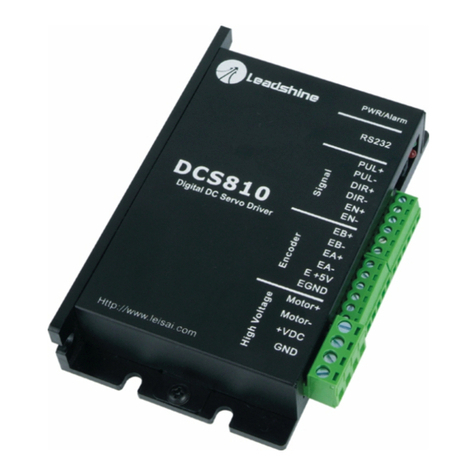
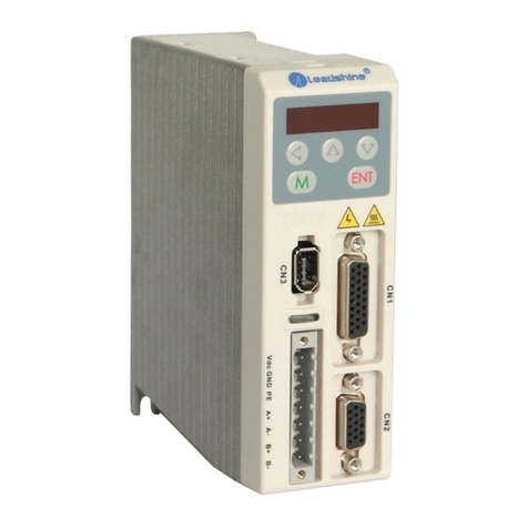
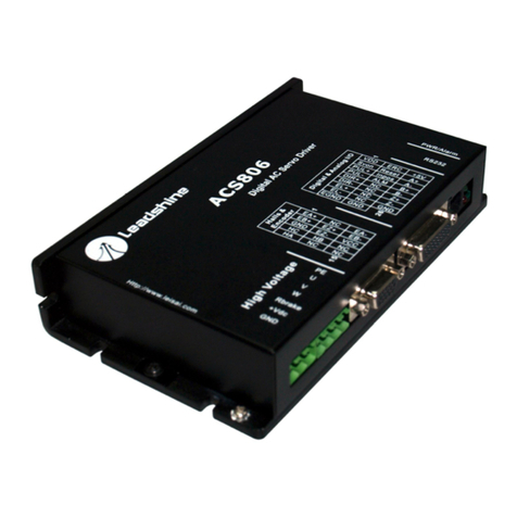
Leadshine Technology ACS306 User manual

Contents
TableofContents
1. Introduction, FeaturesandApplications...................................................................1
Introduction...........................................................................................................1
Features.................................................................................................................1
Applications..........................................................................................................2
2. SpecificationsandOperating Environment..............................................................2
ElectricalSpecifications........................................................................................2
Performance Specifications...................................................................................2
MechanicalSpecifications.....................................................................................3
EliminationofHeat...............................................................................................3
OperatingEnvironmentandParameters................................................................3
3. Connections..............................................................................................................4
ConnectorConfiguration.......................................................................................4
GeneralInformation.....................................................................................4
MoreaboutI/OSignals................................................................................5
ControlSignalConnections...................................................................................6
AlarmSignalConnections.....................................................................................7
EncoderandHall SensorConnections..................................................................7
RS232 Interface Connection..................................................................................8
TypicalConnections..............................................................................................9
4. ServoSetup............................................................................................................10
Install EncoderandHall sensor...........................................................................10
PreparePowerSupply.........................................................................................11
RegulatedorUnregulatedPowerSupply...................................................11
SelectingSupplyVoltage............................................................................11
PrepareController...............................................................................................11
SystemConnectionsandNoisePrevention.........................................................12
WireGauge.................................................................................................12
Contents
CableRouting.............................................................................................12
Twisted Wires.............................................................................................12
CableShielding..........................................................................................13
SystemGrounding......................................................................................13
PowerSupplyConnection..........................................................................13
5. TuningtheServo....................................................................................................14
TestingtheServo.................................................................................................14
TuningtheServo.................................................................................................14
SequenceChartofControlSignals......................................................................16
ProtectionFunctions............................................................................................17
Over-currentProtection..............................................................................17
Over-voltageProtection.............................................................................18
EncoderorHall ErrorProtection................................................................18
Position FollowingErrorProtection...........................................................18
ProtectionIndications.................................................................................18
MaximumPulseInputFrequency.......................................................................18
MotorSpeedCalculation.....................................................................................19
APPENDIX................................................................................................................20
TWELVEMONTHLIMITEDWARRANTY....................................................20
EXCLUSIONS....................................................................................................20
OBTAINING WARRANTYSERVICE..............................................................20
WARRANTYLIMITATIONS.............................................................................20
SHIPPING FAILEDPRODUCT.........................................................................21
ContactUs..................................................................................................................22

A
AC
CS
S3
30
06
6
D
Di
ig
gi
it
ta
al
l
A
AC
C
S
Se
er
rv
vo
o
D
Dr
ri
iv
ve
e
M
Ma
an
nu
ua
al
l
R
Re
ev
v1
1.
.0
0
1. Introduction, Features and Applications
Introduction
Leadshine'sfullydigitalACservodriveACS306 isdevelopedwith32-bit DSP
basedonadvancedcontrolalgorithm.SinceitsinputcommandsarePUL/DIR
signals,theuserscanupgradesteppingdrivestotheACS306 withoutchanging
controlsystems.TheACS306 canofferhighprecision,highspeedand high
reliabilityperformance,andwidelyusedininkjetprinters,engravingmachines,and
etc.Abuilt-incontrollercanbeusedfortestingandtuning.PCbasedandhandheld
configuration&tuningtoolscanmeetdifferenttuningenvironmentsorrequirements.
TheACS306 candrivebothDCbrushless and ACservomotors.Butit ismore
suitablefortheDCbrushless servomotors.ComparetoACS606, theACS306 has
smallersizeandadditionalalarm(fault)signaloutputtoindicateerror.
Features
l Input: 20 -30VDC,
l PeakCurrent: 15A, ContinuousCurrent: 6 A(Max), 10 -200 W
l FOC-SVPWMtechnologies
l PCbasedandhandheldconfigurationtools
l Electronicgearratefrom1/255 to255
l Self-testfunction withtrapezoidalvelocityprofile
l SupportPUL/DIRandCW/CCWcontrolsignals
l Opto-isolated, supportsingle-endedanddifferentialinputs
l Followingerrorlockrangeadjustable
l Over-voltage,over-current, encoderfailureprotections
l 10 latestfailuresself-recordfunction
l Small size, surface-mounttechnology
A
AC
CS
S3
30
06
6
D
Di
ig
gi
it
ta
al
l
A
AC
C
S
Se
er
rv
vo
o
d
dr
ri
iv
ve
e
M
Ma
an
nu
ua
al
l
R
Re
ev
v1
1.
.0
0
Applications
Suitableforlargeandmediumautomationmachinesandequipments,suchasinkjet
printers,engravingmachines,electronicmanufacturingequipments,specialNC
machines,pickandplacedevices,packingdevices, andso on. Particularlyadapttothe
applicationsrequirehighspeed,highprecision, andlowmotornoise.
2. Specifications andOperatingEnvironment
ElectricalSpecifications(Tj =25 /77℉)
ACS306
Parameters Min. Typical Max. Unit
Peakoutputcurrent 0 - 15 A
Continueoutputcurrent 0 - 6 A
Supplyvoltage +20 - 30 VDC
Logicsignalcurrent 7 10 16 mA
Pulseinputfrequency 0 - 200 kHz
Isolationresistance 500 MΩ
Currentprovidedtoencoder - - 100 mA
PerformanceSpecifications(withBLMSeriesMotors)
l Position following error:+/-1 count
l Velocityaccuracy:+/-2rpm
l Maximumacceleration speed(NoLoad):80 rpm/ms2
l Maximumspeed:3000 rpm
l Allowablelowspeedreaches1 rpm
l Positioningaccuracy:+/-1 count
l Suitablefor20 -30 VDCAC/DCservomotors

A
AC
CS
S3
30
06
6
D
Di
ig
gi
it
ta
al
l
A
AC
C
S
Se
er
rv
vo
o
d
dr
ri
iv
ve
e
M
Ma
an
nu
ua
al
l
R
Re
ev
v1
1.
.0
0
Tel: (86)755-264343693Website: www.leadshine.com
MechanicalSpecifications (unit:mm[inch])
Figure2-1:Mechanicalspecifications
EliminationofHeat
l Drive sreliableworkingtemperatureshouldbe<70 [158 ],and motor
workingtemperatureshouldbe<80 [176 ].
l Itisrecommendedtomountthedriveverticallytomaximizeheatsinkarea.
OperatingEnvironmentand Parameters
Cooling Natural coolingorForcedcooling
Environment Avoiddust, oil fog andcorrosivegases
AmbientTemperature 0-50 (32 -122 )
Humidity 40%RH-90%RH
OperatingEnvironment
Vibration 5.9m/s2 Max
StorageTemperature -20 -65 (-4 -149 )
Weight Approx. 180g(6.4z)
A
AC
CS
S3
30
06
6
D
Di
ig
gi
it
ta
al
l
A
AC
C
S
Se
er
rv
vo
o
d
dr
ri
iv
ve
e
M
Ma
an
nu
ua
al
l
R
Re
ev
v1
1.
.0
0
Tel: (86)755-264343694Website: www.leadshine.com
3. Connections
ConnectorConfiguration
GeneralInformation
FeedbackSignalConnector
Pin Signal Description I/O
1 EA+ EncoderchannelA+input I
2 EB+ EncoderchannelB+ input I
3 EGD Signalground GND
4 HW HallsensorWinput I
5 HU HallsensorU input I
6 FG Ground terminalforshielded GND
7 EZ+ Reserve I
8 EZ- Reserve I
9 HV HallsensorVinput I
10 NC Not Connected -
11 EA- EncoderchannelA-input I
12 EB- EncoderchannelB-input I
13 VCC +5V@100mAmax. O
14 NC Not Connected -
15 NC Not Connected -
Control SignalConnector
Pin Signal Description I/O
1 PUL+ Pulsesignalinput+ I
2 PUL- Pulsesignalinput- I
3 DIR+ Directionsignal input+ I
4 DIR- Directionsignal input- I
5 ENA+ Enablesignalinput + I
6 ENA- Enablesignalinput - I
7 ALM+
Alarm(fault)signal + O
8 ALM- Alarm(fault)signal + O

A
AC
CS
S3
30
06
6
D
Di
ig
gi
it
ta
al
l
A
AC
C
S
Se
er
rv
vo
o
d
dr
ri
iv
ve
e
M
Ma
an
nu
ua
al
l
R
Re
ev
v1
1.
.0
0
RS232 CommunicationConnector
Pin Signal Description I/O
1 NC Not connected -
2 +5V +5VpoweronlyforSTU. O
3 TxD RS232transmit. O
4 GND Ground. GND
5 RxD RS232receive. I
6 NC Not connected -
HighVoltageConnector
Pin Signal Description I/O
1 U MotorphaseU O
2 V MotorphaseV O
3 W MotorphaseW O
4 +Vdc DCpowerInput(20-30VDC) I
5 GND PowerGround. GND
MoreaboutI/O Signals
Signal Description
PUL+/PUL-
Pulseinputsignal.Insinglepulse(pulse/direction)mode,thisinputrepresents
pulsesignal,eachrisingorfallingedgeactive(softwareconfigurable);4-5Vwhen
PUL-HIGH,0-0.5VwhenPUL-LOW.Indoublepulsemode(pulse/pulse),this
inputrepresentsclockwise(CW)pulse,activeatbothhigh levelandlow level . For
reliableresponse,pulsewidthshouldbelongerthan0.85μs.Seriesconnect
resistorsforcurrent-limitingwhen+12Vor+24Vused. ThesameasDIRandENA
signals.
DIR+/DIR-
Directionsinputsignal.Insingle-pulsemode,thissignalhaslow/highvoltage
levels,representingtwodirectionsofmotorrotation;indouble-pulsemode
(softwareconfigurable),thissignaliscounter-clock(CCW)pulse,activeatboth
highlevel andlowlevel.Forreliablemotionresponse,DIRsignal shouldbeahead
ofPULsignalby5μsatleast.4-5VwhenDIR-HIGH, 0-0.5VwhenDIR-LOW.
ENA+/ENA-
Enableinputsignal. Thissignalusedforenabling/disablingthedrive.Highlevel
forenablingthedriveand lowlevelfordisablingthedrive.Usuallyleft
UNCONNECTED (ENABLED).
A
AC
CS
S3
30
06
6
D
Di
ig
gi
it
ta
al
l
A
AC
C
S
Se
er
rv
vo
o
d
dr
ri
iv
ve
e
M
Ma
an
nu
ua
al
l
R
Re
ev
v1
1.
.0
0
MoreaboutI/O Signals(Continue )
Signal Description
ALM+/ALM-
Alarm(Fault)signal output.OCoutput, highimpedancewhentheworkingstatusis
normalandlowimpedancewhenover-voltage,over-current,phaseerror,encoder
error,limit error,positionfollowingerrorhappens.
ControlSignalConnections
TheACS306 has3differentiallogicinputstoacceptEnable,PulseandDirection
controlsignalsand1OC(opencollector) outputforalarm(fault)output.These
inputsareisolatedtominimizeoreliminateelectricalnoisescoupledontothe
controlsignals.Recommendusetwistedwiresandshieldingcableforcontrol
signalstoincreasenoiseimmunityininterferenceenvironments.Keepthesewires
farawayfromthepowerlines.Infigure3-2, inputcircuit forthesecontrolsignals
andconnectionstoatypicalmotioncontrollerisillustrated.Figure3-3illustrates
connectionstothecontrollerwithcommon-anodeoutputs.
Figure3-1:Connectionstocontrollerwithdifferential outputs

A
AC
CS
S3
30
06
6
D
Di
ig
gi
it
ta
al
l
A
AC
C
S
Se
er
rv
vo
o
d
dr
ri
iv
ve
e
M
Ma
an
nu
ua
al
l
R
Re
ev
v1
1.
.0
0
Figure3-2:Connectionstocontrollerwithcommon-anodeoutputs
AlarmSignalConnections
TheACS306 has1OC(opencollector) outputforalarm(fault)output.Infigure2,
inputcircuit forthesecontrolsignalsandconnectionstoatypicalmotion controller
isillustrated.Figure3-3illustratesconnectionstothecontrollerwithalarmsignal
outputs.
Figure3-3:Connectionstocontrollerwithalarmsignaloutputs
Encoderand Hall SensorConnections
TheACS306 canacceptbothincrementalencoderandhall effectsensorinputsfor
motorshaftpositionfeedbacks. Notethattwisted-pairshieldedcablingprovidesthe
bestimmunityinelectricallynoisyenvironments.
TheACS306 hasthe+5Vpowertosupplytheencoder&hall sensor.If theencoder
A
AC
CS
S3
30
06
6
D
Di
ig
gi
it
ta
al
l
A
AC
C
S
Se
er
rv
vo
o
d
dr
ri
iv
ve
e
M
Ma
an
nu
ua
al
l
R
Re
ev
v1
1.
.0
0
and hall sensordrainsless than100mA,theACS306 cansupplythemdirectly,and
connectit asFigure3-4. If theencoderdrainsmorethan50mA,useanexternalDC
supplyandconnectit asFigure3-5.
Figure3-4:TheACS306 suppliestheencoderdirectly
Figure3-5:UsingexternalDCpowersupplytosupplytheencoder
RS232 Interface Connection
Figure3-6:RS232 interfaceconnection

A
AC
CS
S3
30
06
6
D
Di
ig
gi
it
ta
al
l
A
AC
C
S
Se
er
rv
vo
o
d
dr
ri
iv
ve
e
M
Ma
an
nu
ua
al
l
R
Re
ev
v1
1.
.0
0
TypicalConnections
AtypicalconnectionoftheACS306 isshownasFigure3-7. Pleaseconsult “Control
SignalConnections”and “EncoderandHall SensorConnections”formore
informationaboutcontrollerandencoderconnections.
Figure3-7:Typical connectionoftheACS306
A
AC
CS
S3
30
06
6
D
Di
ig
gi
it
ta
al
l
A
AC
C
S
Se
er
rv
vo
o
d
dr
ri
iv
ve
e
M
Ma
an
nu
ua
al
l
R
Re
ev
v1
1.
.0
0
4. ServoSetup
Beforeyoustarttheservo,youshouldfollowthebelowsteps.
InstallEncoderand Hall sensor
EncoderandHall sensorprovideinformation ofthemotorshaftpositionand rotor
magneticfieldorientation.TheoutputsignalsfromtheHall sensorhaveabsolute
phaseinformationwhichisusedatmotorstartup.If yourmotorhasno encoderand
hall sensor,youmustmountanencoderandhall sensorproperlyonthemotorbefore
youstart. Pleaseassembletheselectedmoduleaccording toitsfactorymanual.
LeadshineoffersBLMseriesDCbrushless servomotorsformatchingtheACS306.
PleasenotethattheACS306 requiresspecificsequenceoftheback-EMFand hall
sensorstatephasingasfigure4-1. Forthemotorwhichisfromothermanufacturer
ormountedbyyourself,youmayhavetotryall thesixcombinationoftheHU,HV,
HWand/ortheU,V,Wwire.Contact tech@leadhine.com forfurtherinformation
installationstonon-Leadshineservomotor.
Figure4-1:BackEMFandhallsensorsequencerequirementoftheACS306
Pleaseuseshieldedcablestoincreasenoiseimmunityininterferenceenvironments.
Keepthesewiresfarawayfromthepowerlines.

A
AC
CS
S3
30
06
6
D
Di
ig
gi
it
ta
al
l
A
AC
C
S
Se
er
rv
vo
o
d
dr
ri
iv
ve
e
M
Ma
an
nu
ua
al
l
R
Re
ev
v1
1.
.0
0
PreparePowerSupply
RegulatedorUnregulatedPower Supply
BothregulatedandunregulatedpowersuppliescanbeusedtosupplytheDrive.
However,unregulatedpowersuppliesarepreferredduetotheirabilitytowithstand
currentsurge.Ifregulatedpowersupplies(suchasmostswitchingsupplies.)are
indeedused,it isimportanttohavelargecurrentoutputrating toavoidproblemslike
currentclamp,forexampleusing4Asupplyfor3Amotor-driveoperation.Onthe
otherhand,ifunregulatedsupplyisused,onemayuseapowersupplyoflower
currentratingthanthatofmotor(typically50%~70%ofmotorcurrent).Thereason
isthattheDrivedrawscurrentfromthepowersupplycapacitoroftheunregulated
supplyonlyduring theON durationofthePWMcycle,butnotduringtheOFF
duration.Therefore,theaveragecurrentwithdrawnfrompowersupplyis
considerablylessthanmotorcurrent.Forexample,two3Amotorscanbewell
suppliedbyonepowersupplyof4Arating.
Selecting Supply Voltage
TheACS306 canactuallyoperatewithin+20 ~+30VDC,includingpowerinput
fluctuation andbackEMFvoltagegeneratedbymotorcoilsduringmotorshaft
deceleration.Theratedvoltageofthemotorisanimportantparameterwhenselecting
supplyvoltage.Generallyspeaking,donotuseapowersupplyvoltagemorethan5
voltsoftheratedvoltageofthemotor.Highervoltagemaycausebiggermotor
vibrationatlowerspeed,anditmayalsocauseover-voltageprotectionorevendrive
damage.
PrepareController
Prepareacontrollerwithpulseanddirection signals.However,theACS306 hasa
built-inmotioncontrollerforself-testandServoTuning.Thebuilt-inmotioncontroller
cangeneratepulsesignalwithtrapezoidalvelocityprofile.
A
AC
CS
S3
30
06
6
D
Di
ig
gi
it
ta
al
l
A
AC
C
S
Se
er
rv
vo
o
d
dr
ri
iv
ve
e
M
Ma
an
nu
ua
al
l
R
Re
ev
v1
1.
.0
0
SystemConnectionsand NoisePrevention
Afterfinishingtheabovesteps,youcanconnectyourservosystem.Beforeyoustart,
makesurethatthepowerisoff.Connectyoursystemaccording toprevious
connectiondiagrams, andpayattentiontothefollowingtipswhenwiring.
Wire Gauge
Thesmallerwirediameter(lowergauge),thehigherimpedance.Higherimpedance
wirewill broadcastmorenoisethanlowerimpedance wire.Therefore,whenselecting
thewiregauge,it ispreferabletoselectlowergauge(i.e.largerdiameter) wire.This
recommendationbecomesmorecriticalasthecablelengthincreases. Usethefollowing
tabletoselecttheappropriatewiresizetouseinyourapplication.
Current(A) Minimumwiresize(AWG)
10 #20
15 #18
20 #16
CableRouting
All contentsensitivesignalwiresshouldberoutedasfarawayfrommotorpower
wiresand Drivepowerwiresaspossible.MotorpowerandDrivepowerwiresare
majorsourcesofnoiseandcaneasilycorruptanearby signal.Thisissuebecomes
increasinglyimportantwithlongermotorpowerandDrivepowerwireslengths.
TwistedWires
Twistedwireseffectivelyincreasenoiseimmunity.Thesuccessivetwistseliminate
noisetransientsalongthelengthofthecable.Bothsignalcablesand powercables
shouldbeofthetwistedand shieldedtype.Differentialsignalwiresshouldbetwisted
asapair.Thecombinationoftwistedpairwiresandadifferentialsignalsignificantly
addstonoiseimmunity.Powerwiresshouldbetwistedasagroupalongwiththe
ground(orchassis)wire, ifavailable.

A
AC
CS
S3
30
06
6
D
Di
ig
gi
it
ta
al
l
A
AC
C
S
Se
er
rv
vo
o
d
dr
ri
iv
ve
e
M
Ma
an
nu
ua
al
l
R
Re
ev
v1
1.
.0
0
CableShielding
All signalwiresshouldbebundledand shieldedseparatelyfromDrivepowerand
motorpowerwires.Powerwiresshouldalsobebundledandshielded.When
groundingashield,therule-of-thumbistodosoatthe ‘source ofpowerwhile
leavingtheothershieldendopen.Forexample,inthecaseofmotorpowerwires,this
wouldbethedriveside.Ideally,twistedpairsshouldbeindividuallyshieldedand
isolatedfromtheoutershield,whichencompassesall wireswithinthecable. However,
sincethistypeofstringentshieldingpracticeisoftennotrequired,typicalcablesdo
notprovideisolationbetweeninnerandoutershields.
SystemGrounding
Goodgroundingpracticeshelpreduce themajorityofnoisepresentinasystem.All
common groundswithinanisolatedsystemshouldbetiedtoPE(protectiveearth)
througha ‘SINGLE lowresistancepoint.AvoidingrepetitivelinkstoPEcreating
groundloops,which isafrequentsource ofnoise.Centralpointgrounding should also
beappliedtocableshielding;shieldsshouldbeopenononeendandgroundedonthe
other.Closeattentionshouldalsobegiventochassiswires.Forexample,motorsare
typicallysuppliedwithachassiswire.IfthischassiswireisconnectedtoPE,butthe
motorchassisitselfisattachedtothemachineframe,whichisalsoconnectedtoPE,a
groundloopwill becreated. Wiresusedforgrounding shouldbeofaheavygaugeand
asshortaspossible.Unusedwiringshouldalsobegroundedwhensafetodososince
wiresleftfloatingcanactaslargeantennas, whichcontributetoEMI.
Power Supply Connection
NEVER connectpowerandgroundinthewrongdirection,becauseit will damage
theACS306 drive.Thedistance betweentheDCpowersupplyofthedriveand the
driveitselfshouldbeasshortaspossiblesincethecablebetweenthetwoisasource
ofnoise.Whenthepowersupplylinesarelongerthan50 cm,a1000µF/100V
electrolyticcapacitorshouldbeconnectedbetweentheterminal “GND”and the
A
AC
CS
S3
30
06
6
D
Di
ig
gi
it
ta
al
l
A
AC
C
S
Se
er
rv
vo
o
d
dr
ri
iv
ve
e
M
Ma
an
nu
ua
al
l
R
Re
ev
v1
1.
.0
0
terminal “+VDC”.Thiscapacitorstabilizesthevoltagesuppliedtothedriveaswell
asfiltersnoiseonthepowersupplyline. Pleasenotethatthepolaritycannotbe
reversed.
Itisrecommended tohavemultipledrivestoshareonepowersupplytoreduce costif
thesupplyhasenoughcapacity.Toavoidcross interference, DONOT daisy-chain
thepowersupplyinputpinsofthedrives.Instead,pleaseconnectthemtopower
supplyseparately.
5.TuningtheServo
TestingtheServo
You maywishtosecurethemotorsoit can tjumpoffthebench.Turnonthepower
supply,thegreen(Power) LEDwilllight.TheACS306 hasdefaultparametersstored
inthedrive.Ifthesystemhasnohardwareandwiringsproblem,themotorshouldbe
lockedandthedriveshouldbeready.
If themotorjumpsslightlyandtheredLEDimmediatelyturnson(flickers),then
eitherthemotorortheencoderiswiredinreversal.Openthetuningsoftware
ProTunerand checkdrivestatusbyclicking Err_check.Ifit s PhaseError,then
exchangemotorwiresorencoderinputsandtryagain.If it s EncoderError,please
checkencoderanditswirings,andthentryagain.Ifit still doesn tworkafteryou
followedall oftheprevioussteps,pleasecontactusat tech@leadshine.com.
If theredLEDisoff andthemotorisnormal,thenyou canstarttotunetheservo
withselectedtool.PCbasedtuningsoftware ProTuner andhandheldsmall servo
tuningunit STU areavailablefortheACS306.
TuningtheServo
Aservosystemiserror-driven.The “Gain”ofthesystemdetermineshowhardthe
servotriestoreducetheerror.Ahigh-gainsystemcanproducelargecorrecting

A
AC
CS
S3
30
06
6
D
Di
ig
gi
it
ta
al
l
A
AC
C
S
Se
er
rv
vo
o
d
dr
ri
iv
ve
e
M
Ma
an
nu
ua
al
l
R
Re
ev
v1
1.
.0
0
torqueswhentheerrorisverysmall.Ahighgainisrequirediftheoutputisrequired
tofollowtheinputfaithfullywithminimalerror.
Aservomotoranditsloadbothhaveinertia,whichtheservoamplifiermust
accelerateanddeceleratewhileattempting tofollowachangeattheinput.The
presence oftheinertiawill tendtoresultinover-correction,withthesystem
oscillatingbeyondeithersideofitstarget.It scalledUNDERDAMPEDstatus.See
Figure11. Thisoscillationmustbedamped,buttoo muchdampingwill causethe
responsetobesluggish,namelycausethesystemtogetintoanOVERDAMPED
state. Whenwetuneaservo,wearetryingtoachievethefastestresponsewith littleor
noovershoot,namelygetaCRITICALLYDAMPEDresponse.
Figure5-1:Stepandimpulseresponses
Asmentionedinpreviouscontents,theACS306 isadigitalservodriveanditsinput
commandisPUL/DIRsignal.Inotherwords,stepresponsejustexistsineachstep
commandsignal.Foreachstepcommand signalisaverysmall movement,so
OVERSHOOTandSETTLING TIMEbetweeneachstepareverysmall,causing
youhardlycansee astepresponsesuchasFigure11, eveniftheSETPOINTisa
verylargequantityandtheaccelerationisveryhigh.
A
AC
CS
S3
30
06
6
D
Di
ig
gi
it
ta
al
l
A
AC
C
S
Se
er
rv
vo
o
d
dr
ri
iv
ve
e
M
Ma
an
nu
ua
al
l
R
Re
ev
v1
1.
.0
0
However,ifyoutrytoevaluateperformancesofthedigitalservobyinvestigatingits
positiontracking-errororpositionfollowingerror,youmayfindit smucheasier
thaninvestigatingitsstepresponse.Theeasiestwaytogetatracking-erroror
positionfollowingerrorresponseistoinduce animpulseloadonthemotor.See
figure5-1 at “time20”.
LeadshineoffersaWindowsbasedsetupsoftware ProTuner toitscustomersfor
evaluatingservoperformances.Small servotuningunit STU (optional)isavailable
too, andit sforfieldtuningwithoutPC.
TuningservosystemsformedbytheACS306 canbesummarizedasthefollowing
rules:
1. If servosystemisUNSTABLE,thenthefirstthingoftuningistostabilize
thesystem.Youcanincrease DerivativeGain of PositionLoop (Kd)or
decrease ProportionalGain ofPositionLoop(Kp)or IntegralGain of
Position Loop(Ki).
2. If servosystemisUNDERDAMPED,thenincreaseKdordecreaseKpor
Ki.
3. If servo systemisCRITICALLYDAMPED,thenstoptuningand
downloadtheparametersettingstotheDrive sEEPROM.
4. If servo systemisOVERDAMPED,thendecreaseKdorincreaseKpor
Ki.
Sequence ChartofControlSignals
Inordertoavoidsomefault operationsanddeviations,PUL,DIRandENshould
abidebysomerules, shownasfigure5-2.

A
AC
CS
S3
30
06
6
D
Di
ig
gi
it
ta
al
l
A
AC
C
S
Se
er
rv
vo
o
d
dr
ri
iv
ve
e
M
Ma
an
nu
ua
al
l
R
Re
ev
v1
1.
.0
0
Figure5-2:Sequencechartofcontrol signals
Notes:
a) t1:ENmustbeaheadofDIRbyatleast5 µs.Usually,ENAisNC(not
connected). See Connections sectionformoreinformation.
b) t2:DIRmustbeaheadofPULactiveedgebyatleast5 µstoensurecorrect
direction.
c) t3:Pulsewidthnotless than2.5 µs;
d) t4:Lowlevelwidthnotless than2.5 µs.
ProtectionFunctions
Toimprovereliability,thedriveincorporatessomebuilt-inprotectionfunctions.The
ACS306 usesoneREDLEDtoindicatewhatprotectionhasbeenactivated.The
periodictimeofREDis5s(seconds),and howmany timestheREDturnson
indicateswhatprotectionhasbeenactivated.Becauseonlyoneprotectioncanbe
displayedbyREDLED,sothedrivewill decidewhaterrortodisplayaccordingto
theirpriorities.See thefollowing ProtectionIndications tablefordisplaying
priorities.
Over-currentProtection
Protectionwillbeactivatedwhencontinuouscurrentexceeds20A,andREDLED
A
AC
CS
S3
30
06
6
D
Di
ig
gi
it
ta
al
l
A
AC
C
S
Se
er
rv
vo
o
d
dr
ri
iv
ve
e
M
Ma
an
nu
ua
al
l
R
Re
ev
v1
1.
.0
0
will turnononcewithineachperiodictime(5 s).
Over-voltageProtection
Whenpowersupplyvoltageexceeds40±1VDC,protectionwill beactivatedand
REDLEDwill turnontwice withineachperiodictime(5 s).
Encoder orHall ErrorProtection
Noencoderfeedbacksignalsorwrongencoder/hall sensorfeedbacksignalswill
activatethisprotection.REDLEDwill turnonfivetimeswithineachperiodictime
(5 s).
PositionFollowing ErrorProtection
WhenpositionfollowingerrorreachesPositionFollowingErrorLimitparameter
settinginthedrive,thisprotectionwill beactivated.REDLEDwill turnonseven
timeswithineachperiodictime(5s).Notethatwrong motorconnectionwillcause
thisprotectiontoo.Pleasecheck yourmotorconnectionifthisprotectionisactivated
atthestartup.
Attention: Sincethereisnoprotectionagainstpowerleads(﹢,﹣)reversal,it is
criticaltomakesurethatpowersupply leadscorrectly connectedtodrive. Otherwise,
thedrivewill bedamagedinstantly.
ProtectionIndications
Priority Time(s)ofON Sequence wave ofREDLED Description
1st 1 Over-currentprotection
2nd 2 Over-voltageprotection
3th 5 EncoderorHall errorprotection
4th 7 Position followingerrorprotection
MaximumPulseInputFrequency
MaximumPulseInputFrequencyisthehighestfrequencyatwhichthedrivecan

A
AC
CS
S3
30
06
6
D
Di
ig
gi
it
ta
al
l
A
AC
C
S
Se
er
rv
vo
o
d
dr
ri
iv
ve
e
M
Ma
an
nu
ua
al
l
R
Re
ev
v1
1.
.0
0
interpretencoderfeedback.ToconvertthisfrequencytoRPM,usethefollowing
formula:
4
60)(
(max) ×
×
=esEncoderLin
FrequenceInputPulseMax
RPM
MotorSpeedCalculation
Themotorspeedcanbecalculatedasthefollowingformula:
4
60)(
)( ×
×
=esEncoderLin
FrequenceInputPulse
RPMSpeed
A
AC
CS
S3
30
06
6
D
Di
ig
gi
it
ta
al
l
A
AC
C
S
Se
er
rv
vo
o
D
Dr
ri
iv
ve
e
M
Ma
an
nu
ua
al
l
R
Re
ev
v1
1.
.0
0
APPENDIX
TWELVEMONTHLIMITEDWARRANTY
LeadshineTechnologyCo., Ltd.warrantsitsproductsagainstdefectsinmaterials
and workmanshipforaperiodof12 monthsfromshippingdate. Duringthewarranty
period,Leadshinewilleither,atitsoption,repairorreplace productswhichproved
tobedefective.
EXCLUSIONS
Theabovewarrantyshall notapplytodefectsresultingfrom:improperor
inadequatehandlingbycustomer;improperorinadequatecustomerwiring;
unauthorizedmodificationormisuse;oroperationbeyondtheelectrical
specificationsoftheproductand/oroperationbeyondenvironmentalspecifications
fortheproduct.
OBTAININGWARRANTYSERVICE
Toobtainwarrantyservice,areturnedmaterialauthorization number(RMA)must
beobtainedfromcustomerserviceate-mail: tech@leadshine.com beforereturning
productforservice.Customershall prepayshippingchargesforproductsreturnedto
Leadshineforwarrantyservice,andLeadshineshall payforreturnofproductsto
customer.
WA
RRANTYLIMITATIONS
Leadshinemakesnootherwarranty,eitherexpressedorimplied,withrespecttothe
product.Leadshinespecificallydisclaimstheimpliedwarrantiesofmerchantability
and fitness foraparticularpurpose.Somejurisdictionsdonotallowlimitationson
howlongandimpliedwarrantylasts,sotheabovelimitation orexclusionmaynot
applytoyou.However,anyimpliedwarrantyofmerchantabilityorfitness islimited
tothe12-monthdurationofthiswrittenwarranty.
Table of contents
Other Leadshine Technology Servo Drive manuals

Leadshine Technology
Leadshine Technology ACS806 User manual

Leadshine Technology
Leadshine Technology DCS810S User manual

Leadshine Technology
Leadshine Technology Vector Easy H2-506 User manual

Leadshine Technology
Leadshine Technology M760 User manual

Leadshine Technology
Leadshine Technology DB810A User manual

Leadshine Technology
Leadshine Technology DCS810 User manual