Shanghai Siheng Motor KA Series User manual

- 1/27 -
Shanghai Siheng Motor Co Ltd
www.sihengmotor.com
DANGER
It is forbidden to use the product in flammable and explosive occasions, which can
easily cause injury or fire.
It is forbidden to use the product in places with humidity, direct sunlight, dust, salt
and metal powder.
KA Series AC Servo Driver Manual
Safety notes
Danger means that when used incorrectly, it will lead to
danger and personal injury.
Note: When used incorrectly, it will cause danger, personal
injury and possible damage to equipment.
Prohibition: It means strictly prohibiting the behavior,
otherwise it will lead to equipment damage or can not be used.
Use occasion
Wring
Do not connect 220V driver power to 380 power supply, otherwise it will cause
equipment damage or fire.
Please grounding terminal reliably. Poor grounding may cause electric
shock or fire.
Do not connect the output terminal of driver U-V-W motor to three-phase power
supply, otherwise it will cause casualties or fire.
Driver UVW motor output terminal and motor connection terminal UVW must be
connected correspondingly, otherwise the motor may cause equipment damage
and casualties due to speeding.
Wiring please refer to wire wiring, otherwise it may cause fire.

- 2/27 -
Shanghai Siheng Motor Co Ltd
www.sihengmotor.com
Note
Before starting operation, please make sure that you can start the emergency
switch and shut down at any time.
When commissioning, please separate the servo motor from the machine. After the
action is confirmed, the motor is installed on the machine.
After the servo motor stops and restores instantaneously, do not approach the
machine. The machine may suddenly start again.
Do not switch on or off the power frequently, otherwise it will cause overheating
inside the driver.
O
peration
Function
Stop
When the motor is running, do not contact any rotating parts, otherwise it will cause
casualties.
When the equipment is running, it is forbidden to touch the driver and motor,
otherwise it will cause electric shock or scald.
When the equipment is running, it is forbidden to move the connecting cable,
otherwise it will cause personal injury or equipment damage.

- 3/27 -
Shanghai Siheng Motor Co Ltd
www.sihengmotor.com
Product introduction
1.1 Servo Driver Technical Specification
output power(kW)
0.4~0.8KW
1.0~1.5KW
1.7~2.6KW
Motor rated torque
(N·m)
2~4NM
4~10NM
6~15NM
Input power supply
Sing le- phase or thr ee-
phase AC 50 Hz / 60Hz
(
0.85
~
1.1
)
×
220V
Three-phase AC 50 Hz /60Hz
(
0.85
~
1.1
)
×220V
Use
enviro
nment
temperature
Work: Storage at 0 ~55: -20 ~+80.
humidity
Less than 90 %(No dew)
Vibration
Less than
0.5G
(
4.9m/s
2
),
10 Hz
~
60 Hz(Discontinuous operation)
Control method
Position Control, Speed Control and Torque Control
regenerative braking
Built-in (external when built-in resistance power is insufficient)
Control
characteristics
Velocity Frequency Response:≥200Hz
Velocity fluctuation rate: <0.03 (load 0-100%): <0.02 *0.9-1.1) power
supply voltage
(Value corresponds to rated speed)
Speed ratio:1:5000
Pulse frequency:≤ 500kHz
control input
1 Servo Enablation
2 Alarm Clearance
3 CCW Drive Ban
4 CW Drive Ban
5.Deviation counter clearing/speed selection 1_
6.Instruction pulse prohibition/speed selection 2
7.CCW torque limit
8.CW torque limit
Control output
1. Servo Ready Output,
2. Servo Alarm Output,
3. Positioning Complete Output/Speed Achievement Output
position control
Input mode
(1) Pulse + Direction
(2) (2) Two-Phase A/B Orthogonal Pulse
Electronic
gear ratio
1~32767 / 1~32767(default: 10000:1000, i.e. 1000
pulses per cycle)
Feedback
pulse
10000 Pulse / turn
speed control
4 internal speeds (switching between SC1 and SC2 input signals)
Acceleration and
deceleration function
Parameter setting acceleration and deceleration time 1-10000ms (0r-
1000r/min)

- 4/27 -
Shanghai Siheng Motor Co Ltd
www.sihengmotor.com
Monitoring function
Speed, current position, instruction pulse accumulation, position
deviation, motor torque, motor current, bus voltage, absolute rotor
position, instruction pulse frequency, operation status, input and output
terminal signals, etc.
Protection function
Overspeed, overvoltage and undervoltage of main power supply,
overcurrent, overload, abnormal braking, abnormal encoder, abnormal
control power supply, abnormal position, etc.
Applicable load inertia
Less than 5 times the inertia of the motor

- 5/27 -
Shanghai Siheng Motor Co Ltd
www.sihengmotor.com
Installation
2.1
KA02-KA03 (below 400W) Motor Driver Outward Size Diagram
2.2
KA05 (0.6 ~1 kW)Outward Size Diagram of Motor Driver

- 6/27 -
Shanghai Siheng Motor Co Ltd
www.sihengmotor.com
2.3 KA10 (1.0 ~2.6 kW)Outward Size Diagram of Motor Driver
- 7/27 -
Shanghai Siheng Motor Co Ltd
www.sihengmotor.com
2.2.1
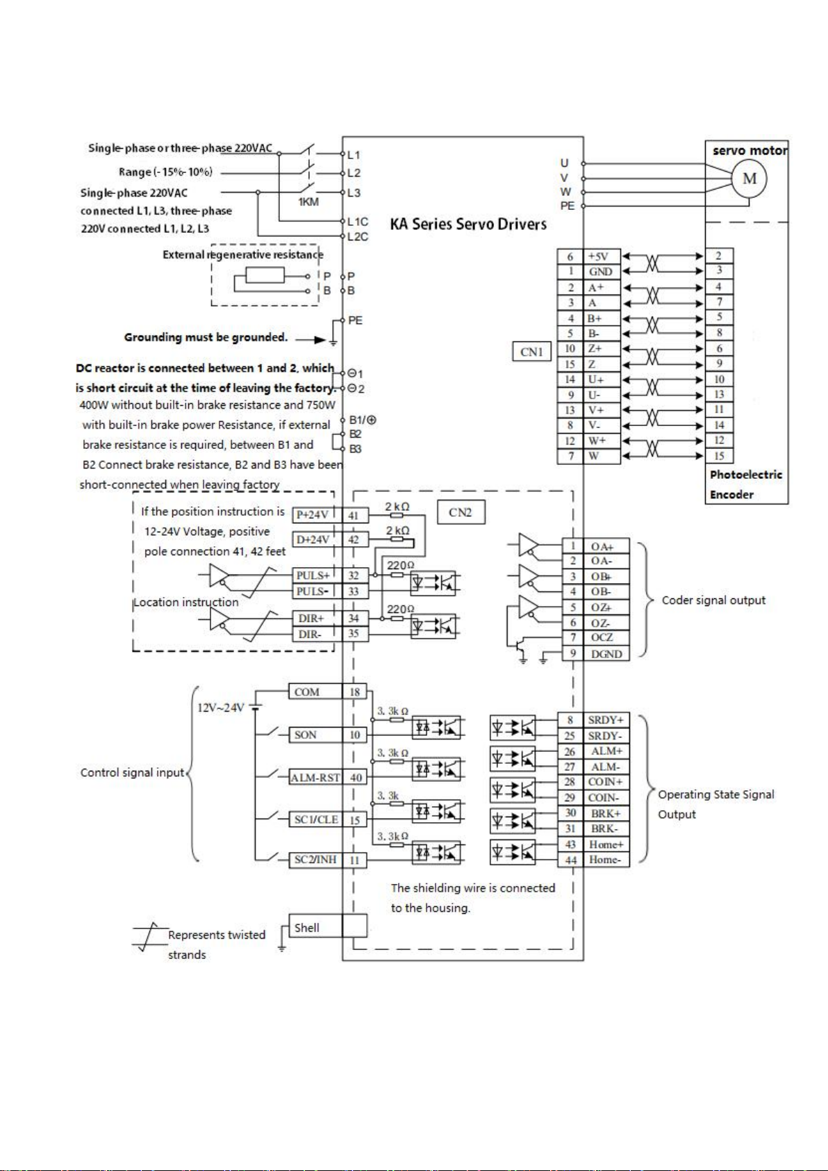
2.4 Standard wiring diagram
Position control mode
Drawing 2-3-1:Position control wiring

- 8/27 -
Shanghai Siheng Motor Co Ltd
www.sihengmotor.com
2.2.2 Speed/Torque Mode Wiring Diagram
Figure 2-3-2: Speed/Torque Mode Wiring

- 9/27 -
Shanghai Siheng Motor Co Ltd
www.sihengmotor.com
2.2.2 Control signal input/output CN2(44 cores terminal )
Control mode is abbreviated as: P stands for position control mode; S stands for speed control mode;
T stands for torque control mode.
Terminal
number
Signal name
Mark
Mode
Function
18
Input Common
End
COM
The common end of the input terminal is used to drive the input optocoupler. It
is connected to 0V or DC 12V-24V, and the current is more than 100mA.
10
Servo Enabling
Input
SON
SON ON: Allows drives to work;
SON OFF: The driver is closed and the motor is in free state. Note 1:
Before calling SON from SON OFF to SON ON,
The motor must be stationary.
Note 2: After calling SON ON, wait for at least 50ms to enter the
command.
40
Alarm clearance
input
ALRS
ALRS ON: Clear system alarm;
ALRS OFF: Keep system alarm.
Note: The alarm with fault code greater than 8 can not be cleared by this
method. It needs power off and maintenance, and then power on again.
15
Instruction pulse
forbidden input
INH
P
INH ON: instruction pulse input is prohibited;
INH OFF: instruction pulse input is valid.
Speed Selection 1
Input
SC1
S
In the speed control mode, the combination of SC1 and SC2 is used to select
different internal speeds.
SC1 OFF, SC2 OFF: Internal speed 1
SC1 ON, SC2 OFF: Internal Speed 2 SC1 OFF, SC2 ON: Internal Speed 3
SC1 ON, SC2 ON: Internal Speed 4
Note: The values of internal velocities 1-4 can be modified by parameters.
11
Speed Selection 2
Input
SC2
S
Counter clearing
CLE
P
CLE ON: When position control, position deviation counter is cleared.
8
Servo ready output
SRDY+
SRDY ON: The control power supply and main power supply are normal, the
driver does not alarm, the servo is ready to output ON (output on);
SRDY OFF: The main power supply is not closed or the driver has an alarm.
The servo is ready to output OFF (output cut-off).
25
SRDY-
26
Alarm output
ALM+
ALM ON: Servo driver without alarm, output ON, output on;
ALM OFF: Servo driver has alarm, output OFF, output cut-off.
27
ALM-
28
L o c a t i o n
c o m p l e t i o n
o u t p u t
( p o s i t i o n
c o n t r o l mo d e ) ;
V e l o c i t y
a r r i v a l
t r a n s p o r t
O u t p u t ( s p e e d
c o n t r o l mo d e ) ;
COIN+
P
COIN ON: When the position deviation counter value is in the set positioning
range, the positioning completes the output ON (output conduction),
otherwise the output OFF (output cut-off).
SCMP ON: When the speed reaches or exceeds the set speed,
Speed reaches output ON (output on), otherwise output OFF (output cut-off).
29
COIN-
S

- 10/27 -
Shanghai Siheng Motor Co Ltd
www.sihengmotor.com
Terminal
number
Signal name
Mark
Mode
Function
30
Mechanical Brake
Release Output
BRK+
This port can be used to control the brake when the motor has a mechanical brake
(power-loss retainer).
BRK ON: The brake transmitter is electrified, the brake is invalid, and the motor can
run.
BRK OFF: The brake is powered off, the brake is effective, the motor is locked and
can not run.
Note: The BRK function is controlled by the driver.
31
BRK-
32
Instruction Pulse
Position Input
PULS+
P
Determine the angle and speed of the motor.
33
PULS-
34
Directional input of
instruction pulse
SIGN+
P
Determine the rotation direction of the motor。
35
SIGN-
20
Analog Speed
Torque Instruction
Input
AS+
S
Differential mode, the input impedance of 10 k Ω - 10 v ~ + 10
v input range
19
AS-
T
22
simulation
AGND
Analog input ground wire
1
Encoder A
Phase Signal
Output
OA+
ABZ differential drive output of encoder (26LS31 output,equivalent to RS422);
Non-insulated output (non-insulated)
2
OA-
3
Encoder B-
phase signal
output
OB+
4
OB-
5
Encoder Z-
phase signal
output
OZ+
6
OZ-
7
Encoder Z-phase
collector open-
circuit output
CZ
In the upper computer, theZ-phase signal pulse is usually very narrow. Please use a
high-speed optocoupler to receive it.
9
Encoder Ground
Wire
GND
Encoder common ground wire

- 11/27 -
Shanghai Siheng Motor Co Ltd
www.sihengmotor.com
2.2.2 encoder signal input terminal CN1(15cores terminal)
Terminal number
Signal name
Mark
Mode
6
5V Power supply
+5V
Servo motor encoder with +5 power supply and common ground;
When the cable is longer, multiple parallel connection should be used
to reduce the line voltage drop。
1
Power common
0V
2
Encoder A+ input
A+
It is connected with photoelectric encoder A+
3
Encoder A- input
A-
Connect with photoelectric encoder A-
4
Encoder B+ input
B+
Connected with photoelectric encoder B+
5
Encoder B- input
B-
Connected with photoelectric encoder B-
10
Encoder Z+ input
Z+
connected with the photoelectric encoder Z+
15
Encoder Z- input
Z-
Photoelectric encoder Z- phase connection
14
Encoder U+ input
U+
Photoelectric encoder U+ phase connection
9
Encoder U- input
U-
Photoelectric encoder U- phase connection
13
Encoder V+ input
V+
Photoelectric encoder V+ phase connection
8
Encoder V- input
V-
Photoelectric encoder V- phase connection
12
Encoder W+ input
W+
Photoelectric encoder W+ connected
7
Encoder W- input
W-
Connected with the photoelectric encoder W-
Shell
Frame Ground
FG
Shield ground terminal

- 12/27 -
Shanghai Siheng Motor Co Ltd
www.sihengmotor.com
Chapter 3 display and panel operation
3.1 Panel shows
The operating interface of the servo driver is composed of 5 LED digital tubes and 5 keys, which
can be used for the state display and parameter setting of the servo driver. The interface layout
is as follows:
Key function description
Button
Button
name
Function
MODE
MODE
Switch the status monitoring mode/parameter mode/alarm mode and
return to the previous menu.
▲
multiply
Add monitor code, parameter number or set value, long press can
increase quickly.
▼
Reduce
Reduce the monitoring code, parameter number or set value, long press
can quickly reduce.
Shift
When setting parameters, press this key to move the selected flicker bit
to the left by one.
SET
Confirm
Go to the next menu, or save the Settings.
Numerical indication
The numerical value USES 5 digital tube displays. The minus sign in front of the
numerical value indicates a negative number. If it is a 5-digit negative number,
all decimal points are lit to indicate a negative number. Some display items are
preceded by an affix character, and if the number of digits is too long to occupy
the position of the prefix character, the prefix character will not be displayed,
only the value.
- 13/27 -
Shanghai Siheng Motor Co Ltd
www.sihengmotor.com
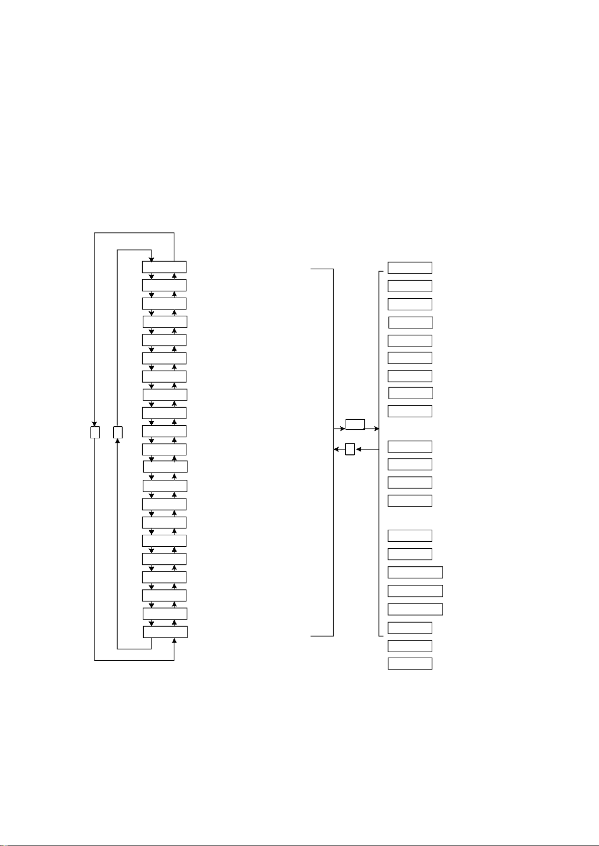
3.2 state monitoring
When the servo driver is powered on, the display will display "Pr. On" for about one
second, and then automatically enter the status monitoring mode. A total of 21 display
state, the user with the, key to select the required display state. You can also change the
value of P00.03 and select the display state of the display after the servo drive is
powered on.
Speed(r/min)
当前位置低4位(脉冲)
当前位置高4位(×10000 脉冲)
位置指令低4位(脉冲)
位置指令高4位(×10000 脉冲)
位置偏差低4位(脉冲)
位置偏差高4位(×10000 脉冲)
电机转矩(%)
电机电流(A)
直线速度(m/min)
当前控制方式 ←
位置指令脉冲频率(kHz)
速度指令(r/min)
转矩指令(%)
一转中转子绝对位置(脉冲)
输入端子状态
输出端子状态
编码器输入信号
运行状态
报警代码
保留
电机速度1000r/min
当前位置125806脉冲
位置指令125810脉冲
位置偏差4脉冲
Torque 70%
电机电流
2.3A
直线速度5.000m/min
控制方式 0
位置指令脉冲频率
12.6kHz 速度指令 -
35r/min
转矩指令 -20%
转子绝对位置
3265 输入端子
输出端子
编码器信号
运行状态 :正在运行
9号报警
U 0
3-2-1 Monitor mode operation block diagram
D -PoS
D -PoS.
D -CPo
D -CPo.
D -EPo
D -EPo.
D -trq
D - I
↓ ↑
D -Cnt
D -Frq
D - CS
D - Ct
D -APo
D - In
D - oUt
D - Cod
D - rn
D -Err
D - rES
D -SPd
D -LSP
Err 9
rn- on
Cod ||||||
oUt ||||
In||||||||
A 3265
t. -20
r. -35
F 12.6
Cnt 0
L 5.000
Enter
I 2.3
t 70
E. 0
E 4
C. 12
C 5810
P. 12
P 5806
r 1000

- 14/27 -
Shanghai Siheng Motor Co Ltd
www.sihengmotor.com
[note 1] r 1000, r is the motor speed code, 1000 means the motor speed is anti-
clockwise 1000r/min, if it is clockwise, negative speed -1000 will be displayed. The
units are r/min.
[note 2] both position feedback pulse POS and position instruction pulse CPO are
values amplified by input electronic gears. The motor encoder feedback position
quantity is composed of POS. (high 4 bits) + POS (low 4 bits) :such as: P
12x1000=125806pcs pulse.
Similarly, the pulse amount of position instruction is also composed of CPO. (high
4 bits) + CPO (low 4 bits),Such as C. 12x10000+C5810=125810pcs pulse
When the encoder is fixed, the Z pulse is fixed as the zero pulse position. D-apo display motor encoder
The pulse value of the output position signal deviating from the zero pulse. If the number of lines of the
encoder is 2500, the display range is 0~9999.
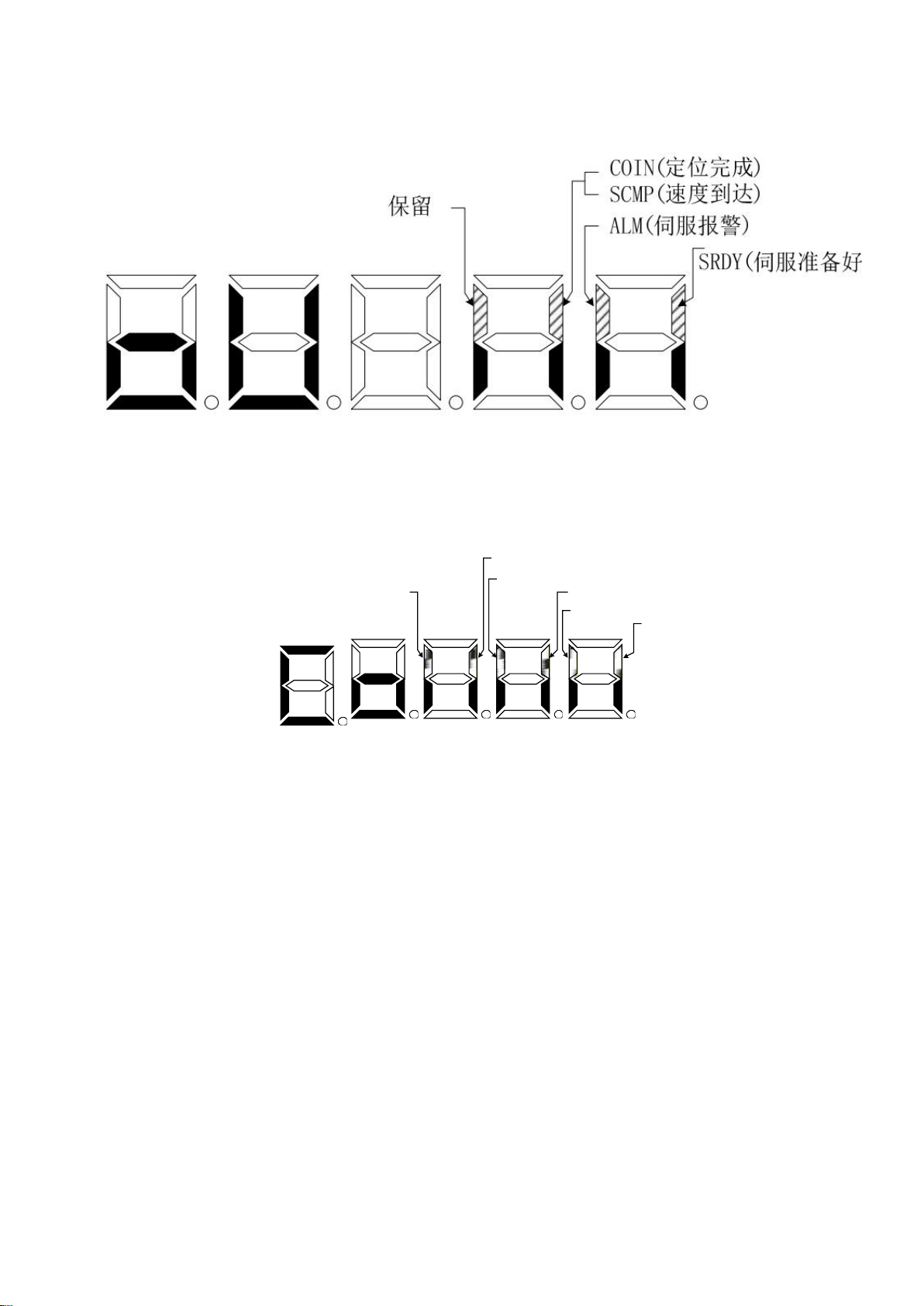
[note 4] the display of input terminal is shown in figure 3-2-2, the display of output terminal is shown in figure
3-2-3, and the display of encoder signal is shown in figure 6-5
Input terminal display (stroke lights up means ON and OFF means OFF)
- 15/27 -
Shanghai Siheng Motor Co Ltd
www.sihengmotor.com
3-2-3 Output terminal display (stroke ON, OFF)
U phase
编码器
V相编
码器W
相
编码器Z相
编码器B
相
编码器A相
3-2-4 Encoder signal display (stroke ON means ON, OFF means OFF)
【Note 5】running state is denoted as:
Rn-oF:The main circuit is not charged and the servo system is not running;
Rn-CH:The main circuit has been charged, and the servo system is not running (the
servo system does not enable or alarm exists).
Rn-on:The main circuit is charged and the servo system is running

- 16/27 -
Shanghai Siheng Motor Co Ltd
www.sihengmotor.com
3.2 Parameter setting
In the menu of the first layer, press [MODE] key to switch to then use Parameter setting mode, and
then use 【▲】、【
▼】button select different parameter groups P00~P05.
Press [SET] key to enter the second layer "parameter number" menu, and use【▲】and【▼】
keys to select different parameter Numbers. Press "SET" key to display the parameter values,
the parameter value of lowest twinkle, twinkle with "◄" button can be moved, with the【▲】or
【▼】key can modify the parameter values. Press [SET] key to save the modified value,
which will be immediately reflected into the control. After that, press【▲】and 【 ▼ 】button to
continue to modify the parameters. After the modification, press [MODE] button to return to the
parameter selection menu. If you are not satisfied with the value being modified, do not press the
[SET] key to confirm. You can press the [MODE] button to cancel, restore the original value of
the parameter, and return to the parameter selection menu.
3-3-1 Parameter setting operation block diagram
Restore parameter default value operation
The operation steps are as follows:
1. Change the password parameter P00.00 to
385, i.e. P00.00 =385.
2. Search the motor model code corresponding to
the current motor according to appendix A, and
input the motor model code into the parameter
P00.01.
3. Modify the parameter P03.07 to 1, and press
[SET] key to restore the default value of the motor.
Then power on again, using the default
parameters of the motor.
P00.

- 17/27 -
Shanghai Siheng Motor Co Ltd
www.sihengmotor.com
Chapter 4 parameters and functions
4.1 list of parameters
The factory values in the following table take the servo driver of 110sjt-m02030 (2N•m,
3000r/min) motor as an example. Relevant parameters of different motors are different。
P00 Parameters
Parameters No
Name
Setting rage
factory
default
Unit
Application way
P00.00
Password
0~9999
315
P,S
P00.01
Motor model code
0~69
60*
P,S
P00.02
Software version (read only)
*
*
P,S
P00.03
Initial display state
0~20
0
P,S
P00.04
Control Strategy Choice
0~8
0
P,S
P00.05
Velocity proportional gain
5~2000
150*
Hz
P,S
P00.06
Velocity integral time constant
1~1000
80*
P,S
P00.07
Torque command filter
1~500
30
%
P,S
P00.08
Speed detection low pass filter
1~500
120
%
P,S
P00.09
Position proportional gain
1~1000
50
1/s
P
P00.10
Position feed forward gain
0~100
0
%
P
P00.11
Position feed forward low pass filter
cutoff frequency
1~1200
300
Hz
P
P00.12
Position command pulse frequency
divider molecule
1~32767
10000
P
P00.13
Position order pulse frequency
divider denominator
1~32767
1000
P
P00.14
Position instruction pulse input mode
0~1
0
P
P00.15
Reverse the direction of the position
command pulse
0~1
0
P
P00.16
Positioning completion range
0~30000
20
Pulse
P
P00.17
Location out of tolerance detection
range
0~30000
200
×100
Pulse
P
P00.18
Location error not valid
0~1
0
P
P00.19
Position order smoothing filter
0~30000
100*
0.1ms
P

- 18/27 -
Shanghai Siheng Motor Co Ltd
www.sihengmotor.com
P01 Parameters
Parameters No
Name
Setting rage
factory
default
Unit
Application way
P01.00
Invalid driver forbidden input
0~1
0
P,S
P01.01
JOG operating speed
-3000~3000
120
r/min
S
P01.02
Acceleration and deceleration time
constant
1~10000
500*
ms
S
P01.03
Maximum speed limit
0~6000
3600
r/min
P,S
P01.04
Internal velocity 1
-3000~3000
0
r/min
S
P01.05
Internal velocity 2
-3000~3000
100
r/min
S
P01.06
Internal velocity 3
-3000~3000
300
r/min
S
P01.07
Internal velocity 4
-3000~3000
-100
r/min
S
P01.08
Reach the speed
0~3000
500
r/min
S
P01.09
reserve
P01.10
Internal CCW torque limitation
0~300
300*
%
P,S
P01.11
Internal CW torque limits
-300~0
-300*
%
P,S
P01.12
External CCW torque limit
0~300
100
%
P,S
P01.13
External CW torque limits
-300~0
-100
%
P,S
P01.14
Speed trial operation, JOG operation
torque limit
0~300
100
%
S
P01.15
reserve

- 19/27 -
Shanghai Siheng Motor Co Ltd
www.sihengmotor.com
P02 Parameters
Parameters No
Name
Setting rage
factory
default
Unit
Application way
P02.00
Analog speed command gain
10~3000
300
r/min/V
S
P02.01
Reverse direction of analog speed
command
0~1
0
S
P02.02
Analog speed command zero offset
compensation
-500~500
0
S
P02.03
Analog speed command has no
control action area
-500~500
0
S
P02.04
Analog speed command filter
1~1000
300
Hz
S
P02.05
Analog torque command gain
1~300
30
%/V
T
P02.06
Reverse direction of analog torque
instruction
0~1
0
T
P02.07
Analog torque instruction zero offset
compensation
-500~500
0
T
P02.08
Maximum speed limit for torque
control
0~4000
2500
r/min
T
P02.09
Analog torque command filter
1~1000
300
Hz
T
P02.10
The lower 4-bit input terminal
enforces the ON control word
0~15
0
ALL
P02.11
High 4 bit input terminal force ON
control word
0~15
0
ALL
P02.12
Reverse control word for lower 4 bit
input terminal
0~15
0
ALL
P02.13
Reverse control word for high 4 bit
input terminal
0~15
0
ALL
P02.14
Reverse control word for output
terminal
0~15
0
ALL
P02.15
Input terminal to dither the time
constant
1~1000
16
0.1ms
ALL
P03 Parameters
Parameters No
Name
Setting rage
factory
default
Unit
Application
way
P03.00
Speed trial run
0~1
0
S
P03.01
JOG Run
0~1
0
S
P03.02
Encoder zero operation
0~1
0
ALL
P03.03
Open loop operation
0~1
0
ALL
P03.04
The initial detection point of software
overcurrent
30~100
90
%
ALL
P03.05
Software overcurrent detection time
10~10000
300
0.1ms
ALL
P03.06
SON servo actuation
0~1
1
ALL
P03.07
System parameters initialized
0~1
0
ALL

- 20/27 -
Shanghai Siheng Motor Co Ltd
www.sihengmotor.com
4.1.1
Parameters function
4.1.2
P00 Parameters
Parameters
No
Name
Function
parame
ter
scope
P00.00
Password
①Used to prevent parameters from being modified by mistake. In general, when you need to
set parameters, first set this parameter to the required password, and then set parameters.
After debugging, set this parameter to 0 at last
to ensure that the parameter will not be modified by mistake in the future.
②Password classification, corresponding to user parameters, system parameters and all
parameters.
③Change the motor model code parameter (P00.01) must use the model code password,
other passwords cannot change this parameter.
④User password is 315, model code password is 385.
0~9999
P00.01
Motor
model
code
①Corresponding to the same series of different power levels of servo drivers and motors
②The parameter default values of different motor model codes are different. When restoring
the default parameter function, the correctness of this parameter must be guaranteed.
③When EEPROM alarm (no. 20) appears, it must reset this parameter after repairing, and
then restore the default parameter. Otherwise, the servo drive will not work properly or
damage.
④When changing this parameter, set the password (P00.00 parameter) to 385 before
changing this parameter.
⑤See this chapter for the detailed meaning of the parameters
0~69
P00.02
software
version
You can view the software version number, but you can't change it.
*
P00.03
Initial
display
state
Select the display status of the display after the servo driver is powered on. 0: Display motor
speed;
1: Display the current position 5 bits lower;
2: Display the current position 5 bits high;
3: Display position instruction (instruction pulse accumulation) is 5 bits lower;
4: Display position instruction (instruction pulse accumulation) is 5 bits high;
5: Display position deviation is 5 bits lower;
6: Display position deviation is 5 bits higher;
7: Display motor torque;
8: Display motor current;
9: Display linear velocity;
10: Display control mode;
11: Display position instruction pulse frequency;
12: Display speed instructions;
13: Display the Torque Instruction;
14: Display the absolute position of the rotor in one turn.
15: Display input terminal status;
16: Display output terminal status;
17: Display input signal of encoder;
18: Display the running status;
19: Display alarm code;
20: Reserve.
0~20
This manual suits for next models
6
Table of contents
Popular Servo Drive manuals by other brands

Delta
Delta ASDA-A+ quick start guide

Coolmay
Coolmay C100E manual

National Instruments
National Instruments NI 9505E Operating instructions and specifications

Rockwell Automation
Rockwell Automation Allen-Bradley Kinetix 300 2097-V31PR0 user manual

YASKAWA
YASKAWA Sigma-V Series user manual

LinMot
LinMot C1450 VS-1S Series installation guide


