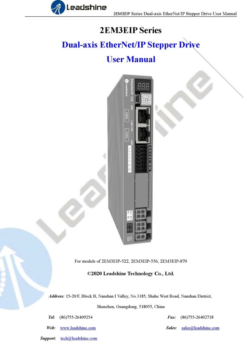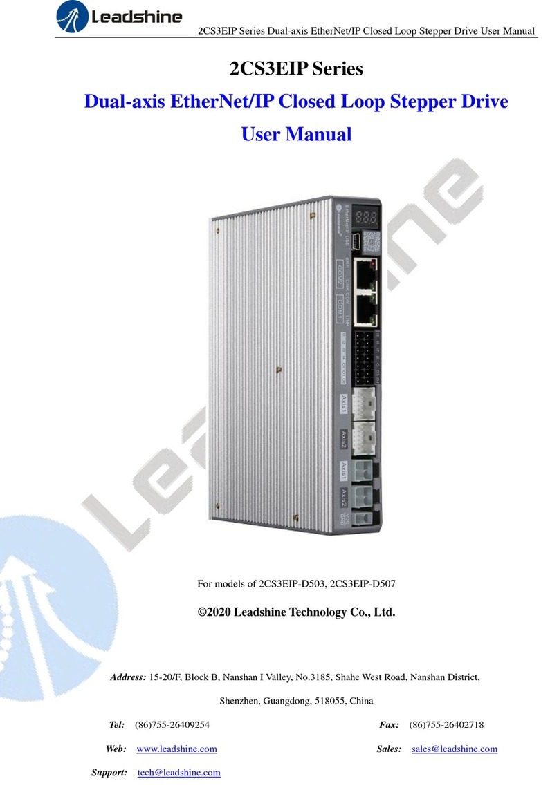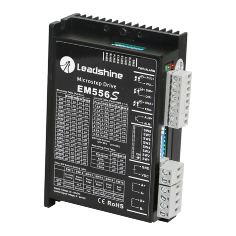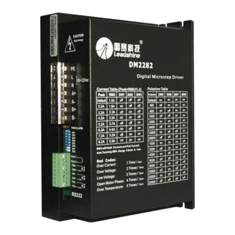
EM422S Digital Stepper Drive User Manual
Table of Contents
1. Introduction..............................................................................................................................................................1
1.1 Features................................................................................................................................................................1
1.2 Applications.........................................................................................................................................................1
2.1 Electrical Specifications ......................................................................................................................................2
2.2 Environment ........................................................................................................................................................2
2.3 Mechanical Specifications...................................................................................................................................2
2.4 Elimination of Heat..............................................................................................................................................3
3. Connection PinAssignments and LED Indication....................................................................................................3
3.1 P1 - Control Connector Configurations...............................................................................................................3
3.2 P2 - Fault Output Connector................................................................................................................................4
3.3 P3 - Power Connector..........................................................................................................................................4
3.3 P4 - Motor Connector..........................................................................................................................................4
3.5 Status LED Lights................................................................................................................................................4
4. Control Signal and Fault Output ...............................................................................................................................4
4.1 Control Signal Connection ..................................................................................................................................4
4.2 Fault output connection .......................................................................................................................................5
5. Stepper Motor Connections ....................................................................................................................................5
5.1 4-lead Motor Connection.....................................................................................................................................5
5.2 6-lead Motor Connection.....................................................................................................................................6
5.3 8-lead Motor Connection.....................................................................................................................................6
5.3.1 Series Connection.....................................................................................................................................6
5.3.2 Parallel Connection...................................................................................................................................6
6. Power Supply Selection...........................................................................................................................................7
6.1 Regulated or Unregulated Power Supply.............................................................................................................7
6.2 Power Supply Sharing .........................................................................................................................................7
6.3 Selecting Supply Voltage.....................................................................................................................................7
7. DIP Switch Configurations .....................................................................................................................................7
7.1 Output Current Configuration (SW1-3)...........................................................................................................8
7.2 Idle Current Configuration (SW4) ...................................................................................................................8
7.3 Micro Step Configuration (SW5-8)..................................................................................................................9
7.4 Filter Time Configuration (SW9-10)...................................................................................................................9
7.5 No Auto Tuning Configuration (SW11)...........................................................................................................9
7.6 Alarm Output Configuration (SW12).............................................................................................................10
7.7 Pulse Edge Configuration (SW13)...............................................................................................................10
7.8 Control Mode Configuration (SW14)...........................................................................................................10
7.9 Shaft Lock Configuration (SW15).................................................................................................................10
7.10 Self-Test Configuration (SW16) ................................................................................................................10
8. Wiring Notes...............................................................................................................................................................10
9. Typical Connection....................................................................................................................................................10
10. Sequence Chart of Control Signals ........................................................................................................................11
