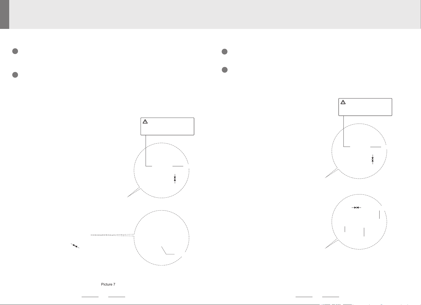
leadsun AE3C User manual

Made in China
Solar Street Light
User Manual
AE3C
A3C.060-C
Thank you for choosing LEADSUN's solar street light.
If you have any question, please consult our customer services
LEADSUN reserves the right to update product appearance, function
and construction without notice.
For any discrepancies in illustration or description, please refer to
individual/real objects.
LEADSUN assures the accuracy and reliability of this manual, but is
not responsible for any loss or damage related to any operation of the
products.
www.leadsunglobal.com
Address: 35373 Condominium
Blvd Zephyrhills, FL 33541.
Phone: (909) 304-1088
Email: [email protected]
LEADSUN Australia PTY LTD LEADSUN Global Limited
LEADSUN INC.
Address: 42 Greens Road,
Dandenong South, Victoria 3175
Phone: +61 1300 281 005
Fax: +61 3 8610 0393
Email: [email protected]
Address: 3/F, No.1 Workshop, No.15,
Pingbei 2nd Road, Nanping, Zhuhai,
Guangdong, P.R. China 519060.
Phone: +86-756-2289712
Fax: +86-756-8682090
Email: sales@leadsunglobal.com
Solar Street Light
User Manual
AE3C
www.leadsunglobal.com

12
Cautions
Product Maintenance
In order to assure that the solar panel receive the light efficiently, please use clear water
to clean the dirt mark on the surface of the panel regularly and prohibit the use of
chemical or abradant which includes chlorobenzene.
Only manufacturer, service agent or qualified personnel can replace the light source or
other circuit components of the lighting device. Without authorization, using the third
party component to replace is prohibited or it would cause serious damage to the
product. if the user disassembles the product without authorization, warranty becomes
void.
If you need to replace the components /accessories, please go to
www.leadsunglobal.com, or contact the local distributor.
Product Recycling
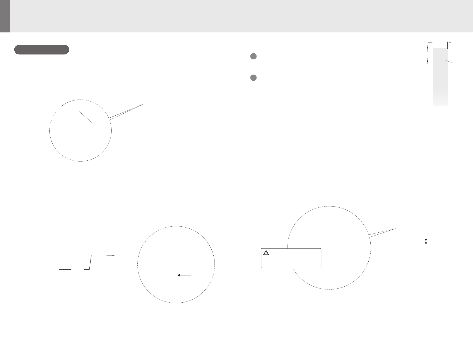
Transportation and Storage
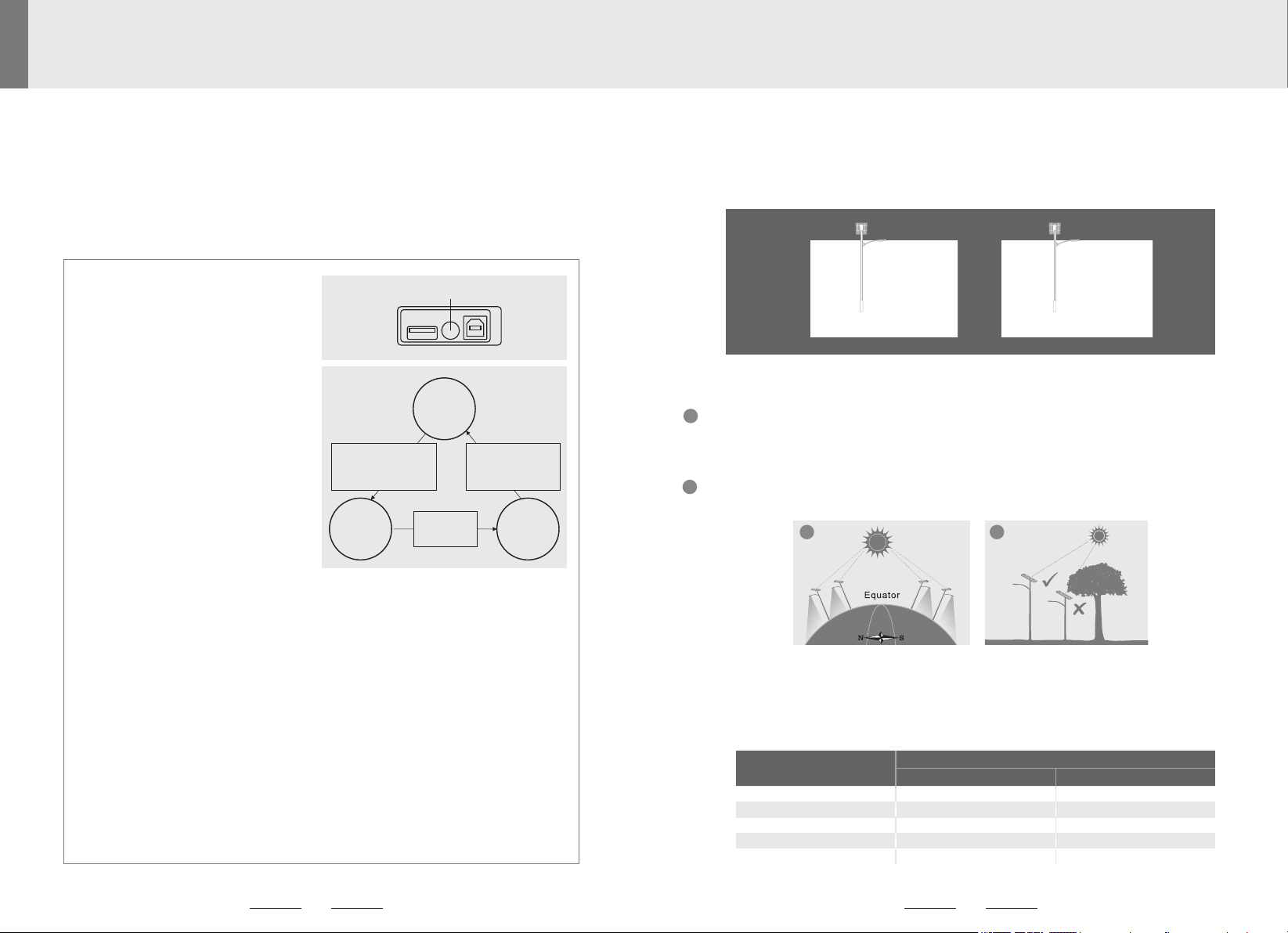
Working Condition
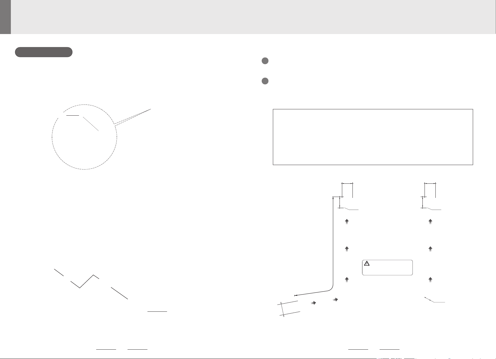
Attention to the Electric Shock
To avoid electric shock, street light with AC adapter must be installed by qualified
electricians and constructors.
The street light with AC adapter is customized product, please confirm the street light
AC adapter is in accord with the local electric supply standard.
Make sure the electric supply power is cut off during the installation and implement
waterproof and insulation protection.
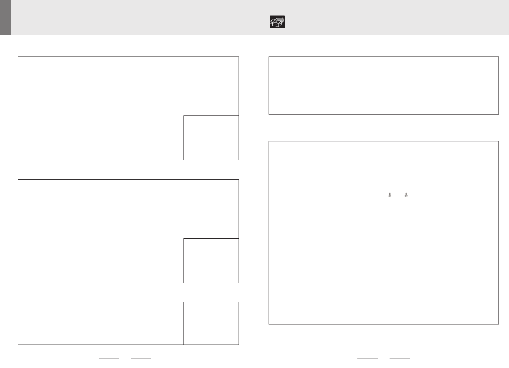
Please read the below cautions carefully before using the AE series solar street
light to avoid physical injury and product failure caused by improper use.
Product protection grade IP66
The product is high-strength structural designed and can pass the 16-level wind speed
simulation test. But the product may still be damaged when used in the harsh hurricane
environment.
Working temperature range from -20℃ to 51℃ ( charging temperature is limited within
0℃ to 51℃). The product with heating function can work from -40℃ to 51℃.
The product contains high capacity lithium-ion battery components, please follow the
aviation transport law. Please regard the product as the flammable and explosive
hazardous substance and store it separately from other goods.
The solar panel of the product is fragile, tier limitation is two layers. No stacking out of
limits and No press with heavy stuff.
Store the product under the temperature from 0℃ to 25℃
It should be charged every six months if the product is stored for long time. please use
the special charger to charge the product (the charger needs additional purchase) in
order to avoid battery or device damage.
All internal parts of AE3C are waterproof and rated IP66. Holes and slits on the
luminaires are designed for heat dissipation and drainage. Metal parts are made of
anodized rustproof aluminum, which can withstand high temperatures and humid
weather. However, it is recommended that you avoid installing the street light in areas
with heavy acid mist or salt influx. The product is made of recyclable high-performance materials and components, please
don't dispose with other household garbage.
Please understand the local rules about the separate collection of electronics and
electrical products, dispose the waste products in the right way that avoids potential
negative effects to environment and human health.

Wireless Parts Description
Part Description
Standard Parts Description
All-In-One Type Split Type
1
2
3
4
5
6
2
3
7 7
8 8
1
4
5
6
LoRa Type
9
4
5
6
2
3
8
1
7
34

Part Description
No.
Parts
Functions
1
Solar Panel
Absorbs and converts solar energy into electricity.
2
Motion Sensor
Detects human movement and control lighting intensity.
3
LED Lamp
Lighting.
4
Type A USB Port of Controller
For battery charging via 14VDC 1.5A power supply
5
Switch Button of Solar Light
To turn on/off the light or switch the light to a different mode
6
Type B USB Port of Controller
For program input
7
Solar Engine Bracket
For mounting the solar engine to the pole
8
Bird Spike
Prevents solar panel contamination from bird droppings
9
LoRa Antenna
For nodes communicating with the Gateway
10
LoRa Antenna
For Gateway communicating with nodes
11
FRP Antenna
For Gateway communicating with nodes
12
SIM Card Slot
Insert 2G/4G card
13
Switch Button of Gateway
To start/restart the gateway
14
Type B USB port of Gateway
For Gateway programming only
15
Gateway indicator lamps
Red indicator is on: Gateway is powered;
Green indicator is on: 4G module is working;
Blue indicator is flashing: 4G data is being transmitted;
Yellow indicator is on: 4G module has access to the Internet.
Wireless Parts Description
Gateway Type with LoRa Type Gateway Type with FRP Antenna
11
10
9 9
4
5
6
12
13
14
15
2
3
8
1
7
56

All-In-One List of Supply
If the solar street light doesn't have wireless control function, there is no relevant
accessories such as antennas. Users can choose this function according to their needs.
Note:
Wireless Parts Description (Optional, With FRP Antenna)
Part List Check if you have all the components listed below before installation, the components and
quantity of each set are as follows:
LED Street Light Bracket of
LED Lamp
M8×90 Screws 4pcs
M8 Spring Washers 4pcs
M8 Nuts 4pcs
LORA Antenna
(Gateway Type 2pcs)
Waterproof Extension Cables
Split Type List of Supply
FREEDOM Classic LED Street Light
Mounting Bracket M12×85 Screw
bolt 1pc
Bird Spike M8×16 Screw 6pcs
M4×8 Screw 3pcs
M4 Lock Washer 3pcs
M4 Flat Washer 3pcs
All-In-One
Split Type Street Light
M8 Screws 6pcs
Split Type Street Light (Optional, With Clamping Bracket)
Fixing Clip
N Line
Lightning Arrester
FRP Antenna
Ground Wire
Bracket Rod
M8 Screw Nut 3pcs
Spare Splint Spare M8 Screws 2pcs
M8 Screw Nut 3pcs
LORA Antenna
(Gateway Type 2pcs)
Mounting Bracket
M12×85 Screw
Bolt 1pc
Bird Spike M8×16 Screw 6pcs
M4×8 Screw 3pcs
M4 Lock Washer 3pcs
M4 Flat Washer 3pcs
Solar Engine
(Optional)
(Optional)
78
M5 Screws 6pcs
Flat Pad 3pcs
Spring Pad 3pcs

3. Installation Altitude and Distance Parameters
Before installing, please according to the height and distance (between the street lights)
restrictions by each respective product type. Consult our product specialists for special
lighting requirements.
Power
Bat Wing Light Source
Installation Height
Installation Distance
15W
4~6m
15~25m
20W
4~6m
15~25m
30W
5~8m
20~30m
50W
7~10m
25~35m
80W
10~12m
30~40m
The product default setting controls the light through photo sensing of the solar panel, and the light
will turn on automatically when it’s dark, and turn off automatically when it’s bright. The street light
will go into the dim mode when no one around at night and it will full brightness when someone
around.
1. Working Mode Description
Please select the appropriate product according to the installation site’s sunlight intensity and
required operating time. If you are in the northern hemisphere, face the solar panels towards the
south as far as possible when installing the solar street light; if you are in the southern hemisphere,
face the solar panels towards the north.
a
For maximum operation efficiency of the solar panels, make sure the sunlight is not blocked by
buildings or trees.
b
2. Installation Direction of Solar Panel
Dim Mode
(E.g. 30% Brightness)
Full Brightness
(100% Brightness)
In the daytime: When connecting the LED street light to the solar engine, the street light
lights up for 20 seconds, and then turns off. It means the solar street light has been
activated automatically.
At night: Press the ON/OFF button for 5 seconds, and then the LED street light switches
on. It means the solar street light has been activated manually. Then, If you short press
the button, the light will switch between ON and OFF.
*
*
Remarks:
ON mode:
The system will work normally, charging in the
daytime and discharging at night.
Transport (idle) mode:
The solar street light will power off in one hour
and then stay in the OFF mode, for
transportation, storage, or maintenance
purpose, until it’s re-activated.
OFF mode:
The system will not work, charge or
discharge.
Power ON:
a. In the daytime:
The solar street lights gets activated and powered on automatically (i.e. to light up for 20s and
then switch off), once it is taken out of the carton (for the all in one type), or when the LED
street light is connected to the solar engine (for the split type).
b. At night:
Long press the ON/OFF button for 5 seconds to get the solar street light activated manually
(i.e. to switch on), with the solar engine connected to the led light.
* * *
*
*
*
*
*Power OFF:
Press the ON/OFF button for 5 seconds when the light is On, to see the light flashes for 3s and
then switches off to come into Transport Mode; Then press the button for 5s again, or have no
operation for one hour, to have the light flash for 1 second and switch off to get the solar street
light power off.
Switch on/off the light:
When the solar street light is activated and powered on, short press the ON/OFF button, and
then the light will switch between on and off.
OFF
Mode
Transport
Mode
Automatically on in the
daytime, or long press 5
seconds.
ON
Mode
Press 5 seconds
or no operation for
more than an hour
Long press
5 seconds
*
910
Product Activation Before Installation
ON/OFF Button
ab

Thread cables from the hole of the bracket and set a proper angle so that the solar panel can
obtain the maximum energy from the sun (each scale on the bracket is 6 degrees). Fix the
bracket by fastening a M12×85 bolt. (See Picture 2)
Picture 1
Picture 2
Drill a Ф10 hole on the lamp pole (88mm away from the top of pole) for
bracket mounting. The hole should align to one of holes on bracket and
keep the light on right way. (See Picture 3-1)
Place the lamp onto the pole and fasten with 6pcs M8 16 screws. Make ×
sure one of screws is screwed into the hole on the pole. (See Picture 3-2)
88
Ø10
Ø75±1
Picture 3-1
Picture 3-2
Use 3 sets of M4×8 screws, lock washers and flat washers to fix the bird spike along the rim of
the top of solar engine. (See Picture 1)
2. Install the Bracket
3. Drill Holes On the Pole and Install the Light
Product Installation
1. Install the Bird Spike
1
2
All In One
M4×8 Screw
Angle Mark
11 12
M8×16 Screw
This M8 Screw must
pass through the reserved
Ø10mm hole on the pole.

2m
Cantilever Threading. The diameter of the cantilever shall not exceed 60mm. Pass two
extension cables through the cantilever and the top of the lamp pole. (Lamp pole shape in the
Picture 6-1 for reference only)
Thread cables from the hole of the bracket and set a proper angle so that the solar panel can
obtain the maximum energy from the sun (each scale on the bracket is 6 degrees). Fix the
bracket by fastening a M12×85 bolt. (See Picture 5)
Picture 5
3. Light Pole Cantilever Wire Threading
2. Install the Bracket
Split Type
1
Use 3 sets of M4×8 screws, lock washers and flat washers to fix the bird spike along the rim of
the top of solar engine. (See Picture 4)
Picture 4
1. Install the Bird Spike
Determine the Direction. Determine the light installation direction first. Drill a Φ10mm hole at
the position which is 88mm away from the top of the pole to fix bracket. (See Picture 6-1)
2
14
13
Firstly, determine and mark the AE3C solar engine and luminaire position according to
the optimum sun radiation and road condition. Then drill a Ф10mm hole at the position
which is 88mm away from the top of the pole to fix bracket. Drill the other Ф25 hole on
the pole where the luminaire is installed for threading extension cables.
Thread 2 extension cables from the small hole for luminaire to the top of lamp pole.
(See Picture 6-2)
Product Installation
M4×8 Screw
M12×85 Screw
Picture 6-1 Picture 6-2
Ø75±1 Ø75±1
Ø60
Ø25
Ø10Ø10
Pay attention to the
direction of the joint
of the waterproof wire.
RHEA MINI LED Street Light Pole (Optional)
88 88

1Mount the luminaire: Connect the luminaire and solar engine with the corresponding cables.
Mount the luminaire on the pole with 4pcs of M8×90 bolts. The maximum torque for those M8
bolts is 14Nm. Do not surpass this torque specification. (See Picture 8)
Mount the AE3C solar engine: Connect all cables together and lock the terminals. Mount
the AE3C solar engine on the pole with 6pcs of M8×16 screws. Make sure one of the screws is
screwed into the Ф10 hole. (See Picture 8)
2
M8×90 Screw
M8 Nuts
1
2
Picture 7
Product Installation
M8×16 Screw
Mount the luminaire: Connect the extension cables from the cantilever to the cables of the
luminaire and lock the connectors. Embed the luminaire bracket into the cantilever and fasten it by 6
M8×16 screw and make sure the luminaire has been installed stably on the pole. Then the installation
is finished. If you use a electric wrench, torque should be set to 14N·m) (See Picture 7).
Mount the AE3C solar engine: Connect all cables together and lock the terminals. Mount the
AE3C solar engine on the pole with 6pcs of M8×16 screws. Make sure one of the screws is screwed
into the Ф10 hole. (See Picture 7)
M8×16 Screw
M8 Spring Washer
Picture 8
4. RHEA MINI LED Street Light (Optional) Installation.
3. FREEDOM Classic LED Street Light Installation.
M8×16 Screw
16
15
This M8 Screw must
pass through the reserved
Ø10mm hole on the pole.
This M8 Screw must
pass through the reserved
Ø10mm hole on the pole.

LORA Terminal Antenna Installation:
Gateway Antenna Installation:
1. Please confirm if the 4G module in the gateway can support the data network covered by the
local carrier before installation.
2. When using the inbuilt gateway with 4G module , users need to insert a SIM card which has
the data service into the gateway. Relevant fee of data service will be charged by the local
carrier.
Cautions:
6. Wireless System Installation (Suitable for Wireless Type)
Connect the antenna to the corresponding positions according to the picture below.
Antenna Installation
18
17
Product Installation
1
How users place the Gateway?
Road Installation
Build lighting group of wireless solar street light along the road. All lamps must be
divided into one or several groups. Each group contains a Gateway and max 120 slave
units. The Gateway should be in the middle of the group.
Gateway street light
120 street lights 120 street lights
Each Gateway covers a range from 800m to 3000m, depending on if there are barriers to block
signal transmission. One Gateway can control 120 slave units.
Gateway street light
Village/Factory/Park Installation:
For installation in village/factory/park area, the Gateway is recommended to be placed
in the center of the area.
2
Silicone Sleeve
Dust Cover
LORA Antenna

FRP Antenna Installation (Optional) Fix the bracket rod to the product bracket with screws and nuts, as shown in . You can Picture 9-3
also use a spare splint to mount the bracket rod on the light pole, as shown in .Picture 9-4
Picture 9-3
Screw the N-head cable into the antenna terminal on the controller and fasten. (See Picture 9-6)
Fix the other end of the ground wire on the light pole or lead it to the ground. The lightning protection
ground resistance is generally not greater than 4 ohms. Finally, tie and fasten the ground wire and the
N-head wire. (See Picture 9-5)
4
3
5
Product Installation
19 20
1Fix the N cable and the ground wire to the lightning arrester respectively,
and then screw the FRP antenna into the lightning arrester, as shown
below. (See Picture 9-1)
Use the fixing clips and screws to fix the FRP antenna to the bracket rod. (See Picture 9-2)
2
Picture 9-1
Picture 9-4
Picture 9-5
Picture 9-6Picture 9-2

Product Installation
No.
Symptoms
Troubleshooting steps
Process
1
No light at night
Check that the lamp can be manually
activated.
Refer to “Activation and Installation” section
on this user guide and run activation tests.
Check if the solar panel is blocked
from the sunlight by houses, trees and
other obstacles.
Clear obstructions or change installation
location.
Check if there is any artificial light
source(s) shining on the solar panel
during the night.
Remove the artificial light source(s) of
interference or change the installation
location.
Examine status of each component
based on the repair guide.
Replace the damaged component(s).
2
A serious shortage
of working time
Check if the solar panel is blocked
from the sunlight by houses, trees and
other obstacles.
Clear obstructions or change installation
location.
Check if the surface of the solar panel
is dusty or covered.
Clean the surface of solar panels as
detailed above.
Examine if the battery pack is
damaged as per the repair guide
instructions.
Replace damaged battery.
3
Lighting does not
follow the normal
operating mode of
turning on and off
Reprogram.
4
Lights fail to turn
on properly when
humans approach
Check if the air temperature close to
human body temperature.
When the air temperature is close to human
temperature, motion detection may slow
down. It will return to normal after the air
temperature changes.
Check if the installation height is too
high.
It is out of motion detection range when
installation height exceeds 8m. It is
recommended to reduce the height or use
other operating modes.
Replace damaged motion sensor or
controllers.
Troubleshooting
With the gateway switched off, i.e., its red indicator lamp is
off, insert the 2G/4G SIM card into the slot according to the
picture.
Please use LEDSUN EDGE APP to remotely control and configure the street light, visit
www.leadsunglobal.com and follow the steps to Download the LEADSUN EDGE.
A. For APPLE users please go to the APP STORE and install the APP 'LEADSUN EDGE' .
B. Android cellphone please visit www.leadsunglobal.com or go to the software platforms like Google
Play to download and install 'LEADSUN EDGE'.
C. PC App please visit http://47.52.88.104:8083/Home/Login
1
Open APP 'LEADSUN EDGE'→Project 'Add Project' →Gateway 'Add Gateway'
→Gateway column 'Add Equipment' →Gateway column 'Reboot'
2Gateway Communication
Push the switch button of the solar engine controller for 5
seconds to active it (This step is not needed if the solar
engine has been activated), then push the switch button of
the Gateway for 5 seconds to see its red indicator lamp
turns on.
Wait until the Gateway's communication is connected
successfully, i.e., its yellow indicator lamp turns on.
Add Gateways/Lights on App
Wait for 2~5 minutes and then refresh the page in APP, the lights are online and displayed under
the Gateway column.
Test Network Communication
Click the light column → Click 'Remote Control' to turn on/off the lights remotely via the App, for
testing the network communication is successful, before you proceed to install the solar light.
Mark Pole Numbers
After the solar light is installed, mark a serial number on its pole as the pole number. And on the App,
change the Equipment Name of the solar light to the same as its pole number for future maintenance
convenience. Open and keep the GPS access of your mobile phone, open LEADSUN EDGE App
within 1m of the light pole, and update/get the Longitude and Latitude coordinates of the solar light on
the page of “Edit Equipment”. This is very important for analyzing the light’s network signal status.
2
3
4
Software Operation Instruction
1
Insert SIM Card
#13 is the switch button of the Gateway.
Ensure the SIM card cutting edge is face down and
the magnetic stripe is away from the indicator light.
Cautions:
13
21 22
Other manuals for AE3C
1
Table of contents
Other leadsun Outdoor Light manuals
Popular Outdoor Light manuals by other brands

IKEA
IKEA SOLSKUR manual

Quoizel
Quoizel LNG8407CHB Assembly instruction sheet

Patriot Lighting
Patriot Lighting Leonia-LG-BK installation manual

Access Lighting
Access Lighting SLANT DLC 20786LED installation instructions

Somogyi Elektronic
Somogyi Elektronic home NLTG 1 instruction manual

BEGA
BEGA 24 326 Instructions for use