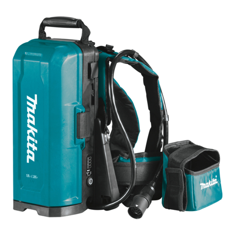
Makita PDC1500 User manual

EN Portable Power Pack INSTRUCTION MANUAL 12
PTBR Adaptador de Baterias Tipo Mochila MANUAL DE INSTRUÇÕES 21
FR Support d’alimentation portable MANUEL D’INSTRUCTIONS 31
DE Rückentragbare Akku-Bank BETRIEBSANLEITUNG 42
IT Gruppo di alimentazione portatile ISTRUZIONI PER L’USO 53
NL Draagbare voedingseenheid GEBRUIKSAANWIJZING 64
ES Unidad Portátil de Alimentación Eléctrica MANUAL DE INSTRUCCIONES 75
PT Adaptador de Baterias Tipo Mochila MANUAL DE INSTRUÇÕES 86
DA Bærbar strømforsyning BRUGSANVISNING 96
EL 105
TR KULLANMA KILAVUZU 116
SV Bärbart strömpaket BRUKSANVISNING 125
NO Bærbar lader BRUKSANVISNING 134
FI Kannettava tehoyksikkö KÄYTTÖOHJE 143
LV LIETOŠANAS INSTRUKCIJA 152
LT NAUDOJIMO INSTRUKCIJA 161
ET Portatiivne akukomplekt KASUTUSJUHEND 170
PL 179
HU Hordozható tápegység HASZNÁLATI KÉZIKÖNYV 190
SK NÁVOD NA OBSLUHU 199
CS NÁVOD K OBSLUZE 208
SL Prenosna polnilna enota NAVODILA ZA UPORABO 217
SQ Paketë elektrike portative MANUALI I PËRDORIMIT 226
BG 235
HR 246
MK 255
SR 266
RO Bloc de alimentare portabil 276
UK 286
RU 297
KK 308
ZHCN 便携电源装置 使用说明书 319
ZHTW 背負式電池包 使用說明書 329
KO 배부식 내장형 배터리 취급 설명서 339
ID Paket Daya Portabel PETUNJUK PENGGUNAAN 347
MS Pek Kuasa Mudah Alih MANUAL ARAHAN 357
VI 367
TH 376
FA 395
AR 402
PDC1500


2
1
7
3
2
4
5
3
17
16
14
11
8
6
12
10
18
13
9
3
15
Fig.1
1
Fig.2

3
32
1
Fig.3
1
3
2
Fig.4
1
Fig.5
1
2
Fig.6
1 2
Fig.7
1
2
3
4
5
6
7
1
2
3
4
5
6
7
1
2
3
4
5
6
7
1
2
3
4
5
6
7
Fig.8

4
1
Fig.9
1
Fig.10
1
Fig.11
2
1
Fig.12

5
1
Fig.13
1
Fig.14
1
1
Fig.15
1
Fig.16
1
Fig.17
Fig.18

6
Fig.19
Fig.20
1
2
Fig.21
Fig.22
12
3
Fig.23
1
Fig.24
1
Fig.25

7
1
Fig.26
1
Fig.27
Fig.28
Fig.29
Fig.30
Fig.31
Fig.32

8
Fig.33
Fig.34
Fig.35
Fig.36
Fig.37
Fig.38
Fig.39
Fig.40

9
Fig.41
Fig.42
Fig.43
Fig.44
Fig.45
1
1
Fig.46

10
Fig.47
Fig.48
2
1
Fig.49
2
1
Fig.50

11
2
1
Fig.51
2
1
Fig.52
1
Fig.53
1
Fig.54
1
Fig.55
Fig.56
Fig.57

12 ENGLISH
ENGLISH (Original instructions)
SPECIFICATIONS
Model: PDC1500
Dimensions
(L x W x H)
369 mm x 312 mm x 131 mm *1
Rated voltage D.C. 36 V - 40 V max
Battery capacity 43.55 Ah
Battery type Rechargeable Lithium-ion
Charging time 450 minutes
Net weight Battery 10.9 kg *1
Shoulder harness assembly 2.0 kg *2
*1. Without shoulder harness assembly, adapters, and charger.
*2. Without adapter pocket
Applicable charger
WARNING: Only use the charger listed above.
Use of any other chargers may cause injury and/or
Intended use
The portable power pack is suitable for long working
hours, since it enables the battery and the tool or
machine to be separated.
This unit can be used with the following tools or
machines.
-
tion to portable power pack)
About this instruction manual
The term “unit” in this instruction manual refers to por-
table power pack. The portable power pack consists of
the battery and shoulder harness assembly.
Compatible tool or machine
category
*1. Except for top handle chain saw (DUC252 /
DUC302 / DUC352 / DUC256 / DUC306 / DUC356 /
DUC406 / DUC256C)
*3. Except for DUX60 when used in combination with
blower attachment
The compatible category of tool or machine is subject
to change without notice. Refer to the latest instruction
manual for the information on the compatible category
of tool or machine.
WARNING: Never use this unit with tools or
machines categorized below. Using this unit with
non-compatible tools or machines may cause per-
sonal injury or malfunction.
part is protected by a cover
NOTICE: If you use the nylon cord when you use
the unit with the following models, be sure to use
the tool in the following combination:
DUR364L / DUR365U / DUR366L /
Cutting tool and
cutting diameter
Nylon cutting head with cutting diameter
of 350 mm
Nylon cord diameter 2.0 mm
*. The nylon cutting head is not available depending on the region
of your residence.
NOTE:
For DUB362
In a high temperature environment, the machine may
stop during operation due to the protection system of
the machine.

13 ENGLISH
Symbols
The followings show the symbols which may be used
for the equipment. Be sure that you understand their
meaning before use.
Read instruction manual.
To reduce the risk of injury, keep the cord
away from obstacles.
Do not expose battery to water or rain.
Do not short-circuit the battery.
Li-ion
Only for EU countries
Due to the presence of hazardous com-
ponents in the equipment, waste electrical
and electronic equipment, accumulators
and batteries may have a negative impact
on the environment and human health.
Do not dispose of electrical and electronic
appliances or batteries with household
waste!
In accordance with the European Directive
on waste electrical and electronic equip-
ment and on accumulators and batteries
and waste accumulators and batteries,
as well as their adaptation to national law,
waste electrical equipment, batteries and
accumulators should be stored separately
and delivered to a separate collection point
for municipal waste, operating in accor-
dance with the regulations on environmen-
tal protection.
This is indicated by the symbol of the
crossed-out wheeled bin placed on the
equipment.
SAFETY WARNINGS
Portable power pack safety
warnings
1. Be sure to read the instruction manual of the
tool or machine before use.
2. Do not pick up or carry this unit by holding
only the cord. Do not pull the cord while you
are wearing or using this unit.
3.
the socket from the tool or machine.
4. When you leave the tool or machine, be sure to
remove the socket from the tool or machine, or
remove the unit from your body.
5. Be careful not to trip over the cord during
operation.
6. Do not use this unit on an unstable surface, or
unstable high places.
7. During operation, keep the cord away from
obstacles. The cord caught by obstacles may
Do not insert the adapters into the charger.
9. Inspect the unit including cords and harness
before use. If they are damaged, ask your local
Makita Authorized Service Center for repair.
10. When attaching the cord to the cord holder, be
sure to attach it slowly and securely.
11. Always make sure that the tool or machine is
attempting to perform inspection or mainte-
nance of the tool or machine.
12. When using this unit with a tool or machine
equipped with a blade, be sure to keep the
cord away from the blade, and be careful not to
cut the cord.
13. When wearing the unit, do not put on anything,
such as safety harness or shoulder belt, which
may interfere the emergency detachment func-
tion of the unit.
14. Do not use this unit while you are climbing up
in a tree.
15. Do not use this unit when you are wearing
16. Do not expose this unit to sparks.
17. When using this unit without wearing it or
installing the unit to the tool or machine, be
sure to lay down the unit.
Do not disassemble, repair, or modify the unit.
19. Be careful not to entangle the harness or belt
by the tool or machine.
20. When using the unit, be careful not to cut the
cords with the tool or machine.
21. When you stand the unit upright using the
battery stand, be sure to place the unit on the
22.
water away from the plug of the unit.
23. Do not use the tool or machine near high-volt-
age power lines.
24. Use the charger dedicated to the unit only. Do
not use other chargers.
25. Do not damage the case of the battery or place
anything on the unit.
26. Do not step on the unit or sit on the unit.
27. Do not carry the unit by holding the battery
stand.
Store the unit indoors.
29. When storing the unit, avoid direct sunlight
and rain, and store it in a place where it does
not get hot or humid.
30.
and battery stand.
31. Do not hang anything from the battery stand.
32. If the cord of the battery becomes hot, stop
using the tool or machine and disconnect the
adapter and cool down the unit including the
cord.
33. When operating the tool or machine with this
unit at high places, be sure to wear a safety
harness.
34. When you carry the unit, be sure to remove the
socket from the tool or machine.
35. Do not wash the shoulder harness with water
or detergent.

14 ENGLISH
Important safety instructions for
battery
1. Before using battery, read all instructions and
cautionary markings on (1) battery charger, (2)
battery, and (3) product using battery.
2. Do not disassemble battery.
3. If operating time has become excessively
shorter, stop operating immediately. It may
result in a risk of overheating, possible burns
and even an explosion.
4. If electrolyte gets into your eyes, rinse them
out with clear water and seek medical atten-
tion right away. It may result in loss of your
eyesight.
5. Do not short the battery:
(1) Do not touch the terminals with any con-
ductive material.
(2) Avoid storing battery in a container with
etc.
(3) Do not expose battery to water or rain.
A battery short can cause a large current
breakdown.
6. Do not store and use the tool/machine and
battery in locations where the temperature
may reach or exceed 50 °C (122 °F).
7. Do not incinerate the battery even if it is
severely damaged or is completely worn out.
Be careful not to drop or strike battery.
9. Do not use a damaged battery.
10.
to the Dangerous Goods Legislation require-
ments.
forwarding agents, special requirement on pack-
aging and labeling must be observed.
-
ing an expert for hazardous material is required.
national regulations.
battery in such a manner that it cannot move
around in the packaging.
11. When disposing the battery, remove it from the
tool and dispose of it in a safe place. Follow
your local regulations relating to disposal of
battery.
12. Use the battery only with the products speci-
Installing the battery to non-com-
explosion, or leak of electrolyte.
13. If the tool/machine is not used for a long
period of time, the battery must be removed
from the tool.
14. Keep the battery away from children.
SAVE THESE INSTRUCTIONS.
CAUTION: Only use genuine Makita batteries.
have been altered, may result in the battery bursting
charger.
Tips for maintaining maximum
battery life
1. Charge the battery before completely dis-
charged. Always stop tool/machine operation
and charge the battery when you notice less
tool power.
2. Never recharge a fully charged battery.
Overcharging shortens the battery service life.
3. Charge the battery with room temperature at
10 °C - 40 °C (50 °F - 104 °F). Let a hot battery
cool down before charging it.
4. Charge the battery if you do not use it for a
long period (more than six months).
PARTS DESCRIPTION
Fig.1
1Base plate 2Lock button 3Cord holder 4
5 6Battery stand 7Battery Handle
9 10
charger
11 Battery charger 12 Socket of battery
charger
13 Adapter for 36 V - 40 V
max (optional accessory)
14 Adapters for 36 V
accessory)
15 Adapter pocket 16 Waist belt
17 Socket Shoulder harness
assembly *
----

15 ENGLISH
FUNCTIONAL
DESCRIPTION
CAUTION: Always be sure that the unit is
-
tion on the unit.
Charging the unit
CAUTION: After charging is complete, be
sure to remove the power plug of the battery
charger from the AC voltage source, and remove
the socket of the battery charger and attach the
cap of the battery.
NOTICE: The battery charger is intended for
charging MAKITA portable power pack only. Never
use it for other purposes or for other manufactur-
er's batteries.
NOTICE: When the battery charger is connected
to the unit, the tool or machine does not start. In
this case, remove the battery charger from the
unit.
NOTICE: If the temperature of the battery
becomes low or high during charging, the
charging may stop. In this case, wait until the bat-
tery becomes ordinary temperature by warming
up or cooling down the battery, and then restart
the charging.
1. Remove the cap of the battery by turning it.
Fig.2: 1. Cap
2. Align the protrusion on the socket of the battery
charger with the counterpart on the plug of the unit, and
then attach the socket to the plug by turning the socket.
Fig.3: 1.2. Socket 3.
3.
proper AC voltage source.
4. After the charging is complete, remove the socket
of the battery charger, and then attach the cap of the
battery.
During charging, the main power lamp lights up in red
and the indicator lamps indicate the remaining battery
capacity. When the charging is complete, the main
Main
power
lamp
Indicator lamps Remaining
capacity
Lighted Blinking
Charging
(75% to
100%)
Charging
(50% to
75%)
Charging
(25% to
50%)
Charging
(0% to
25%)
Power button and battery indicator
CAUTION: Make sure that the tool or machine
Otherwise,
the tool or machine may start suddenly and cause an
injury.
NOTE: If you turn on the tool or machine right after
you turn on the unit, the tool or machine may not start.
In this case, restart the tool or machine again.
Fig.4: 1.2. Indicator lamp 3.
power lamp
To turn the power on, press the power button. The main
press the power button for a few seconds.
NOTE: If the unit and connected tool or machine are
The main power lamp blinks in green under the follow-
ing conditions:
not connected to the socket of the unit.
In this case, connect the plug of the adapter or
power tool/machine to the socket of the unit.
In this case, charge the unit.
the unit is low.
In this case, cool down the unit, or warm up the
unit.
If the main power lamp blinks in red and green alter-
If the main power lamp keeps blinking in red and green
alternately after turning the power on, ask your local

16 ENGLISH
Indicating the remaining battery
capacity
remaining battery capacity. The indicator lamps light up
for approximately 5 seconds.
Indicator lamps Remaining
capacity
Lighted Blinking
75% to 100%
50% to 75%
25% to 50%
0% to 25%
Charge the
battery.
The battery
may have
malfunctioned.
NOTE: Depending on the conditions of use and the
from the actual capacity.
NOTE: If the tool or machine has indicator lamps for
remaining battery capacity, do not refer to the indica-
tor lamps of the tool or machine but to the indicator
lamps of this unit.
NOTE: If the multiple indicator lamps blink, the bat-
tery is overheated. In this case, cool down the battery.
Tool/Machine/Battery protection
system
The tool or machine is equipped with a tool or machine
and battery protection system. This system automat-
machine and battery life. The tool or machine will auto-
matically stop during operation if the tool, machine, or
battery is placed under one of the following conditions:
Overload protection
When the tool, machine, or battery is operated in a
manner that causes it to draw an abnormally high
current, the tool or machine automatically stops. In
application that caused the tool or machine to become
overloaded. Then turn the tool or machine on to restart.
Overheat protection
When the tool, machine, or battery is overheated, the
tool or machine automatically stops. In this case, let the
tool or machine and battery cool before turning the tool
or machine on again.
Overdischarge protection
When the battery capacity is not enough, the tool or
machine stops automatically and an indicator lamp
blinks when you press the power button. In this case,
remove the battery from the tool or machine and charge
the battery.
Low battery indication lamp of
Adapter for 36 V - 40 V max
Optional accessory
you of low or no battery capacity.
When the indication lamp is blinking, the remaining
battery capacity gets low.
When the indication lamp lights up, the battery capacity
is depleted or battery protection system is activated.
NOTE: When using the tool/machine continuously,
tool/machine may automatically stop without blinking
the indication lamp.
NOTE: The timing when the indication lamp blinks
varies depending on the ambient temperature and
battery status.
Fig.5: 1. Low battery indication lamp
Using the adapter pocket
CAUTION: Do not use this unit with the cord
adapter pocket.
You can put the adapters into the adapter pocket as
Fig.6: 1. Adapter 2. Adapter pocket
ASSEMBLY
CAUTION: Always be sure that the unit is
unit.
Assembling the unit
1. Insert the base plate into the plate of the shoulder
harness.
Fig.7: 1.2. Base plate
2. Determine the position of the base plate according
to your height by referring to the table.
Fig.8

17 ENGLISH
Choose a number on the base plate according to your
height by referring the table below.
Number on base plate Height
7
6
5
4
3165 - 175 cm
2160 - 170 cm
1Up to 165 cm
3. Slide the base plate to the desired position while
the base plate.
Fig.9: 1. Lever
4. Attach the battery to the shoulder harness assem-
Fig.10: 1. Battery
CAUTION: Be careful not to pinch your
shoulder harness assembly when attaching the
battery.
CAUTION: Make sure that the battery is
Otherwise, the battery may fall when you put on the
unit or use the unit, and cause an injury. If you can
-
tery is not locked completely.
Fig.11: 1. Red indicator
CAUTION: When removing the battery, press
Fig.12: 1. Handle 2. Lock button
Attach the adapter pocket to the waist belt with the hook
Fig.13: 1. Adapter pocket
NOTE: The adapter pocket can be attached on either
left or right side of the waist belt.
OPERATION
CAUTION: When wearing the unit, be sure
to put shoulder harness on your both shoulders.
Otherwise, the unit may fall when you wear the unit or
use the unit, and cause an injury.
CAUTION: When wearing the unit, be sure to
wear the unit on your back. Otherwise, the unit may
fall during operation and cause an injury.
CAUTION:
machine before turning on the unit, or connecting
the plug of the adapter or power tool/machine
to the socket of the battery. Otherwise, the tool or
machine may start suddenly and cause an injury.
NOTE:
unit.
Using the cord holders
Attach the cord of the battery using the cord holders of
the shoulder harness assembly.
Fig.14: 1. Cord holder
You can attach the cord of the battery to the cord hold-
Fig.15: 1. Cord holder
You can also attach the cord of the battery using only
Fig.16: 1. Cord holder
You can also attach the cord of the battery to the cord
Fig.17: 1. Cord holder
CAUTION: Be sure to attach the cord to the
shoulder harness on the left side only or right
side only so that the cord does not cross the
shoulder harness.
Fig.18
CAUTION: Attach only the cord of the battery
to the cord holders. Do not attach the cord of the
adapters or power tool/machine to the cord hold-
ers. Attaching the cord of the adapters or power tool/
machine may invite accident and cause an injury.
Fig.19
Fig.20
Connecting the unit to the tool or
machine
1. Remove the battery from the shoulder harness
assembly.
2.
battery. When pulling out the cord, be sure to set the
Fig.21: 1. Cord 2. Holder
You can also pull out the cord downward as shown in
Fig.22
3. Attach the battery to the shoulder harness
assembly.
4. Insert the plug of the adapter or power tool/
machine into the socket of the battery all the way so that
the arrow mark on the plug is aligned with that on the
socket.
Fig.23: 1.2. Socket 3. Arrow mark
NOTICE: When disconnecting the plug and
socket, do not hold the cords but hold the plug
and socket. Otherwise, the cords may be damaged
and cause a malfunction of the unit.
NOTE: The plug and socket are disconnected if a
certain load is applied.

18 ENGLISH
5. Install the adapters to the tool or machine in the
same way as the battery cartridge.
Fig.24: 1. Adapter
For 36 V (18 V x 2) battery-powered tool or
machine, use the adapters for 36 V (18 V x 2).
For 36 V - 40 V max battery-powered tool or
machine, use the adapter for 36 V - 40 V max.
For direct connection type tool or machine,
no adapter is required.
NOTE: The direction of the cord of the adapter can be
6.
seconds.
Fig.25: 1.
NOTICE: When installing adapters to the tool or
machine, be sure to install the adapter equipped
If you install the adapters incorrectly, the adapter
equipped with 2 cords cannot be inserted all the
way. In this case, do not insert the adapter forci-
bly. Otherwise, the tool or machine may be damaged.
Fig.26: 1. Adapter with 2 cords
Fig.27: 1. Adapter with 2 cords
Putting on the unit
CAUTION:
unit, be sure to disconnect the tool or machine
from the unit.
CAUTION:
base plate, be sure to lay down the unit so that the
Before putting on the unit, adjust the position of the
base plate to suit your body by referring to the section
for assembly in this instruction manual.
NOTE:
bottom of battery slightly so that the stand does not
touch the ground, and then slide the base plate.
Fig.28
1.
Fig.29
2. Adjust the length of the shoulder harness so that
the waist belt is at your waist.
Fig.30
comfortably.
Fig.31
position.
Fig.32
Fig.33
3. Lock the buckle of the waist belt.
Fig.34
4. Adjust the length of the waist belt.
Fig.35
5. Adjust the length of the shoulder harness.
Fig.36
Fig.37
6. Lock the buckle of the chest belt.
Fig.38
7. Adjust the position of the chest belt.
Fig.39
Be sure to attach the chest belt within the area shown
Fig.40
8. Adjust the length of the chest belt.
Fig.41
9.
Fig.42
10.
Fig.43
11.
Fig.44
12. Check the following:
unit are level.
Fig.45
NOTE: You can work comfortably when you put on
the unit so that the top of the shoulder harness and
the top of the unit are level.
NOTE: When the waist belt is in the recommended
Setting down the unit
CAUTION: When setting down the unit, place
unit does not fall.
CAUTION: Before setting down the tool or
and make sure that the cutting tool has com-
pletely stopped.
CAUTION: Be sure to unlock the chest belt
and the waist belt in order.
Before setting down the unit, remove the tool or
machine from the unit.
Unlock the buckle of the chest belt, then the buckle of
the waist belt, and then set down the unit slowly.
Fig.46: 1. Buckle

19 ENGLISH
unlock the buckle of the chest belt, then the buckle of
the waist belt, and then remove one of the shoulder
straps.
Fig.47
Remove the other shoulder strap, and hold the handle
of the unit while holding the shoulder strap. Set down
handle.
Fig.48
Using the hanging band
Optional accessory
CAUTION: Before operation, make sure that
the hanging band is properly attached to the
hanger on the tool.
You can use the hanging band for cordless grass trim-
mer or cordless pole saw with this unit.
Attaching the hanging band
1. Attach the hooks of the hanging band to the rings
of the shoulder harness or waist belt as shown in the
method appropriate for your usage.
Fig.49: 1. Ring 2. Hook
Fig.50: 1. Ring 2. Hook
Fig.51: 1. Ring 2. Hook
Fig.52: 1. Ring 2. Hook
2. Attach the hook to the tool.
Fig.53: 1. Hook
Detaching the tool
holding the tool to release the tool from the shoulder
harness.
Fig.54: 1. Lever
NOTE: The buckle is not equipped depending on the
type of band.
Emergency detachment
1.
and the waist belt to unlock the buckles.
Fig.55: 1. Lever
2. While holding the tool with one hand, remove one
of the shoulder straps with the other hand.
Fig.56
3. While holding the tool with one hand, remove the
rest of the shoulder straps with the other hand.
Fig.57
MAINTENANCE
CAUTION: Always be sure that the unit is
-
tion or maintenance.
NOTICE: Never use gasoline, benzine, thinner,
alcohol or the like. Discoloration, deformation or
cracks may result.
repairs, any other maintenance or adjustment should

20 ENGLISH
TROUBLESHOOTING
State of abnormality Main power lamp Cause Remedy
The tool or machine does
not start.
-The charger is connected to the
unit.
Remove the charger from the unit.
The lamp lights up in
green.
The adapters are not installed to the
tool or machine.
Install the adapters to the tool or
machine.
Check that the adapters are
installed securely.
The tool or machine, or the cords of
the adapters are overheated.
Cool down the tool or machine, unit
and adapter. After cooling down,
The tool or machine, or the unit is
broken.
Centers for repair.
The lamp blinks in green. The plug of the adapter or power
tool/machine and the socket of the
battery are not connected.
Connect the plug and the socket.
Check that the plug and socket are
connected securely.
The unit is overheated, or the
temperature of the unit is low.
Cool down the unit, or warm up
the unit.
The remaining battery capacity is
not enough.
Charge the battery.
The lamp blinks in red and
green alternately.
The unit has detected an
abnormality.
The tool or machine, or the unit is
broken.
Centers for repair.
The lamp does not light up. The unit is not turned on. Turn on the unit.
The remaining battery capacity is
not enough.
Charge the battery.
The unit is broken.
Centers for repair.
Charging does not start
when the charger is
connected.
The lamp blinks in red. The unit is overheated, or the
temperature of the unit is low.
Cool down the unit, or warm up
the unit.
The lamp blinks in red and
green alternately.
The unit or charger has detected an
abnormality.
Remove the socket of the battery
charger, and then connect it again.
The unit or charger is broken.
Centers for repair.
The lamp does not light up. The charger is not connected to the
proper AC voltage source.
Connect the charger to the proper
AC voltage source.
The socket of the charger is not
connected properly.
Connect the socket of the charger
properly.
The power cord of the charger is not
connected to the charger properly.
Connect the power cord to the
charger properly.
The unit or charger is broken.
Centers for repair.
OPTIONAL
ACCESSORIES
CAUTION: These accessories or attachments
are recommended for use with your Makita prod-
The use of any other
accessories or attachments might present a risk of
injury to persons. Only use accessory or attachment
for its stated purpose.
If you need any assistance for more details regard-
Center.
NOTE: Some items in the list may be included in the
product package as standard accessories. They may
Other manuals for PDC1500
1
Table of contents
Languages:
Other Makita Power Pack manuals

Makita
Makita PDC01Z User manual

Makita
Makita PDC01 User manual

Makita
Makita PDC1200 User manual

Makita
Makita PDC1200 User manual

Makita
Makita PDC1200 User manual

Makita
Makita PDC1200 User manual

Makita
Makita PDC01 User manual

Makita
Makita PDC1500 User manual

Makita
Makita PDC01 User manual

Makita
Makita PDC1200 User manual