manuals.online logo
Brands
  1. Home
  2. •
  3. Brands
  4. •
  5. Lectrosonics
  6. •
  7. Receiver
  8. •
  9. Lectrosonics UDR700 User manual

Lectrosonics UDR700 User manual

SELECT Down
Information and Status Display
MENU
SELECT Up POWER Switch
77
77
700 Series Quick00 Series Quick
00 Series Quick00 Series Quick
00 Series Quick
Frequency Switches
Audio Output XLR Jack Coarse Fine
StarStar
StarStar
Start Guidet Guide
t Guidet Guide
t Guide
1) Locate Receiver. Place the receiv er where it will not be
subjected to extreme temperature variations, bumped or
dropped. Try to route all power, antenna and audio cables so
they do not cross walkways or aisles.
2) Connect Power. For AC operation, connect the female end Analog Audio
PHASE Switch
of the power cord to the AC input Output Control
jack on the rear panel and plug 5) Turn On Receiver and Find Clear Frequency - When the
the other end into a suitable Main Tuning Menu appears, observe the RF Level Indicator
electrical outlet (90-240 VAC, LEDs. (If the Main Tuning Menu is not displayed, press and
50-60 Hz). release the MENU button to step through the menu
If external DC power is used, selections until it is displayed.)
connect a power cord from If any of the RF Level Indicator
SELECT Down POWER
SELECT Up
MENU
RF Level Indicator
Information and Status Display
the DC power source to LEDs glow or blink, use
the External Power AC Power Input Jack the SELECT Up or Down
Connector. (This cable will 90 to 240 VAC, 50-60 Hz button to locate a clear
have to be fabricated. See channel (no RF activity)
External Power Connector
700 Series Operations Manual for 11-17 VDC from one of the current
specifications on this cable.) factory preset frequency Press SELECT Up and
group. Down to choose a new
3) Connect Antennas. You can use either two remote antennas security level (default is
or two whip antennas with 90-degree connectors to operate If a clear channel Level 1), then press MENU
the UDR700; however, the is not available Main Tuning Menu to finalize the selection.
using one of the
operating range may be less The Information and Status
factory preset
with the whip antennas than Display displays a message
with the remote antennas. frequencies, Transmitter Frequency Select indicating the selected
Switch Code
When using remote antennas, press and hold Group Tuning Menu
GRPA CHAN
1 20
668 .
100 8. 7V 20
Security Level (1, 2 or 3).
the MENU button,
them at least three feet from
for best performance place
then press the 8) Generate Encryption Key - Press MENU to enter the Key
SELECT Up or
each other and as high as Generation Menu. “MAKE NEW KEY? ^” will be displayed
Down button to tune across the entire 25.5 MHz frequency
possible with a direct line of in the Information and Status Display.
sight path to the transmitter. block (in 100 kHz steps) to locate one.
4) Preset Receiver and Connect to Sound System. Preset 6) Set Transmitter Frequency Switches - If necessary, install
the UDR700 controls as follows and connect the Audio a fresh battery, then set the Frequency Select Switches on
Output XLR jack to your audio equipment input: the associated transmitter(s) to the two-digit code displayed
on the right side of the Information and Status Display.
M A E NE
W YE
K
K ?
Audio Monitor Level Control (front panel) to min. (CCW) Press the SELECT Up button to begin the process, or press
Fine (100 KHz) Frequency
0 1 2
3
4
5
6
7
8
9
A
B
C
D
E F 0 1F 2
3
4
5
6
7
8
9
A
B
C
D
E
(See illustration in Step 5.) The digits
PHASE Switch (rear panel) to “0” MENU to cancel creating a new key and return to the MAIN
represent the positions of
Analog Audio Output Control (rear panel) to -40 (full CCW) TUNING MENU display.
the Coarse (1.6 MHz) and
Follow the Information and Status Display instructions until
Select Switches. (In the “NEW KEY TO TX ^” appears.
example, “2” represents
the Coarse setting and “0” is
the Fine setting.)
N E K E T O
Y
W X
T
1.6 MHz 100 KHz
Audio Monitor Level Control Frequency Select Switches
0 1 2
3
4
5
6
7
8
9
A
B
C
D
E F 0 1 2
3
4
5
6
7
8
9
A
B
C
D
E F
7) Set Security Level - Set the UDR700 Power switch to OFF,
then press and hold the SELECT Down button while setting
the Power switch to On.
Antenna Input “B” Antenna Input “A”
UM700
SELECT Down
SELECT Up
Modulation LEDs
Transmitter
Level 1: 1 blink
Level 2: 2 blinks
Level 3: 3 blinks
Note
In Security Levels 1 and 2, you may program as many transmitters as you like to match the
receiver. Repeat steps 9 and 10i for each transmitter. This will transmit the same encryption Modulation LEDs
key to each transmitter; however, once you leave this prompt, this particular encryption key
can never again be sent out of the Security jack to a transmitter. A new encryption key will
have to be created. In Security Level 3, each encryption key may be sent to only one
transmitter.
Audio Level Control
-20 -10
UT700
Transmitter
UM700
9) Connect Key Cable. Remove the Battery Compartment
Cover (UT700 only), then connect the Key Cable between
the transmitter and the UDR700.
Caution
The UM700 and UT700 Key Cables are different.
Modulation LEDs
UT700
Hand Held
Transmitter
UT700
Battery Compartment
Belt Pack
Transmitter
UT700
Cover
UM700 Input Jack
Power LED UM700 Key Cable
Security Jack
UT700 Key
Cable
Encryption Link
Security Jack
UM700
10) Transfer Encryption Key - Turn on the transmitter, verify
battery condition, and then press the SELECT Up on the
UDR700 to transfer the encryption key to the transmitter.
The Power LED on the UT700 and the two Modulation LEDs
on the UM700 blink to confirm receipt of the new key.
Input Jack
Power LED
Power ON/OFF
Switch Power LED
Antenna SMA Power On/Off
Conenctor Switch
UT700
Transmitter
Remove the Key Cables. On the UM700, connect
microphone to Input Jack and attach antenna to the SMA
connector.
11) Set Transmitter Gain - Depending on the unit, position the
microphone in the location where it will be used. While
speaking or singing at the same voice level that will be used
during the actual program, observe the Modulation LEDs on
the UM700 and the UT700. Adjust the Audio Level Control
until the -20 LED occassionally blinks red and the -10 LED
glows green.
Audio Level
Control
Signal Level -20 LED -10 LED
Less than -20 dB Off Off
-20 dB to -10 dB Green Off
-10 dB to +0 dB Green Green
+0 dB to +10 dB Red Green
Greater than +10 dB Red Red
Note
The transmitter Audio Level Control should not be used to control the volume of your sound
system or recorder levels. This gain adjustment matches the transmitter gain with the user’s
voice level and microphone positioning. Different voices usually require different settings of
the Audio Level Control. Check this adjustment as each new person uses the system, or
adjust it for the loudest voice. Also, the UDR700 receiver needs at least 5 uV of RF signal to
begin operating - this is the approximate squelch threshold. Between 5 uV and 10 uV,
reception will be marginal and brief gaps in the audio may occur if the receiver squelches.
Check to see that at least the lowest four RF LEVEL LEDs stay lit when the transmitter is
turned on.
12) Set System Audio Levels. Set the UDR700 rear panel
Analog Audio Output Control to midrange. Operate the
wireless system and adjust the receiver analog audio output
level as required for your
equipment. Try different
settings of the Analog
Audio Output Control
listen to the results. If
the output of the receiver
is too high, you may hear
distortion or a loss of the
natural dynamics of the
audio signal. If the PHASE Switch
Analog Audio Output
output is too low, you Control
may hear steady noise
(hiss) along with the audio. Use the Phase switch if
necessary to ensure proper signal polarity at the Audio
Output XLR Jack.
Note
If the security level is set to “1” or “2”, the receiver must be powered on before the
transmitter. If the security level is set to “3”, communications do not begin until a fresh key
is transferred.
13) Perform and Walk Test. Perform a walk test of the wireless
microphone system prior to the actual event. Keep in mind
that the security level has a direct impact on system
operation. (See 700 Series Operations Manual, The 700
Series Encryption System) Mark, or otherwise note, the
maximum range of the receiver in order to minimize
performance problems.
PROTECT THE ENCRYPTION KEY
The encryption key is never displayed and once a key transfer session is
complete, the existing key can never again be transferred out the receiver’s
security port. However, the key is stored inside the transmitter and the
receiver, so you should treat the equipment as you would a key, storing it in a
safe place for as long as the key is important.
For maximum security, it is recommended that you set a new key often,
ideally before and after each use of the system, and that you always store the
equipment in a physically secure location.
Note that in Security Level 3, the equipment itself enforces the most
important part of this policy, namely that no key shall ever be used more than
once.

Other manuals for UDR700

2

This manual suits for next models

2

Other Lectrosonics Receiver manuals

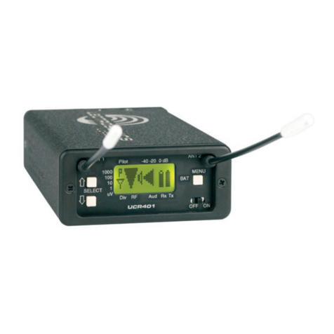
Lectrosonics UCR401 User manual

Lectrosonics

Lectrosonics UCR401 User manual

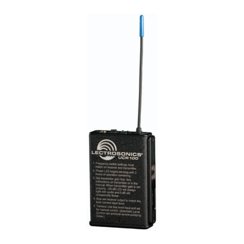
Lectrosonics UCR100 User manual

Lectrosonics

Lectrosonics UCR100 User manual

Lectrosonics UCR211 User manual

Lectrosonics

Lectrosonics UCR211 User manual

Lectrosonics UCR411A-25 User manual

Lectrosonics

Lectrosonics UCR411A-25 User manual

Lectrosonics IFBR1a/E01 User manual

Lectrosonics

Lectrosonics IFBR1a/E01 User manual

Lectrosonics M2R User manual

Lectrosonics

Lectrosonics M2R User manual

Lectrosonics Venue User manual

Lectrosonics

Lectrosonics Venue User manual

Lectrosonics R400A User manual

Lectrosonics

Lectrosonics R400A User manual

Lectrosonics R172 User manual

Lectrosonics

Lectrosonics R172 User manual

Lectrosonics LR User manual

Lectrosonics

Lectrosonics LR User manual

Lectrosonics CR175 User manual

Lectrosonics

Lectrosonics CR175 User manual

Lectrosonics UCR310 User manual

Lectrosonics

Lectrosonics UCR310 User manual

Lectrosonics IFBR1B User manual

Lectrosonics

Lectrosonics IFBR1B User manual

Lectrosonics UR190 User manual

Lectrosonics

Lectrosonics UR190 User manual

Lectrosonics DCR822 User manual

Lectrosonics

Lectrosonics DCR822 User manual

Lectrosonics SRc-941 User manual

Lectrosonics

Lectrosonics SRc-941 User manual

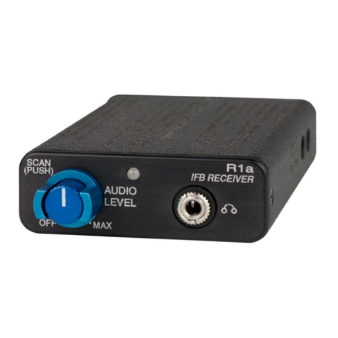
Lectrosonics IFBR1a User manual

Lectrosonics

Lectrosonics IFBR1a User manual

Lectrosonics UDR200C User manual

Lectrosonics

Lectrosonics UDR200C User manual

Lectrosonics R175 User manual

Lectrosonics

Lectrosonics R175 User manual

Lectrosonics CR187 User manual

Lectrosonics

Lectrosonics CR187 User manual

Lectrosonics UR195 User manual

Lectrosonics

Lectrosonics UR195 User manual

Lectrosonics DSR4 User manual

Lectrosonics

Lectrosonics DSR4 User manual

Lectrosonics R400 User manual

Lectrosonics

Lectrosonics R400 User manual

Lectrosonics duet M2R-X User manual

Lectrosonics

Lectrosonics duet M2R-X User manual

Popular Receiver manuals by other brands

Black Box AC155A-R2 user manual

Black Box

Black Box AC155A-R2 user manual

Sky Master DCI 35 operating instructions

Sky Master

Sky Master DCI 35 operating instructions

US Automatic 030214 Use and installation  manual

US Automatic

US Automatic 030214 Use and installation manual

Entrematic Ditec GOPAV installation manual

Entrematic

Entrematic Ditec GOPAV installation manual

Wyrestorm MX-0404-HDBT-H2A-KIT quick start guide

Wyrestorm

Wyrestorm MX-0404-HDBT-H2A-KIT quick start guide

Hi-Tec OPTIMA SL Instruction

Hi-Tec

Hi-Tec OPTIMA SL Instruction

Icom FP-561 Service manual

Icom

Icom FP-561 Service manual

Vemco VR2Tx quick guide

Vemco

Vemco VR2Tx quick guide

Phorus PR1 owner's manual

Phorus

Phorus PR1 owner's manual

AOR The New Classic AR3030 manual 

AOR

AOR The New Classic AR3030 manual 

Scientific Atlanta Explorer 8300 user manual

Scientific Atlanta

Scientific Atlanta Explorer 8300 user manual

Motorola MINITOR VI user guide

Motorola

Motorola MINITOR VI user guide

Fisher 400 Operating instructions and warranty

Fisher

Fisher 400 Operating instructions and warranty

Just Add Power Cardware 2G HD over IP Dealer support manual

Just Add Power Cardware

Just Add Power Cardware 2G HD over IP Dealer support manual

Onkyo HT-R820THX Service manual

Onkyo

Onkyo HT-R820THX Service manual

Sony MSAC-PC1 operating instructions

Sony

Sony MSAC-PC1 operating instructions

Sony Cablevision DHG-M55CV Hardware Setup Instructions

Sony

Sony Cablevision DHG-M55CV Hardware Setup Instructions

Harman Kardon AVR 320 owner's manual

Harman Kardon

Harman Kardon AVR 320 owner's manual

manuals.online logo
manuals.online logoBrands
  • About & Mission
  • Contact us
  • Privacy Policy
  • Terms and Conditions

Copyright 2025 Manuals.Online. All Rights Reserved.