OPERATING INSTRUCTIONS
The following instructions assume that the TH1 will feed the Main bus of a MAP system, and that the Aux Output of
the AC1 Controller module will feed the Transmit Input of the TH1. This is the standard setup for the TH1 when used
with a sound system configured around the MAP system.
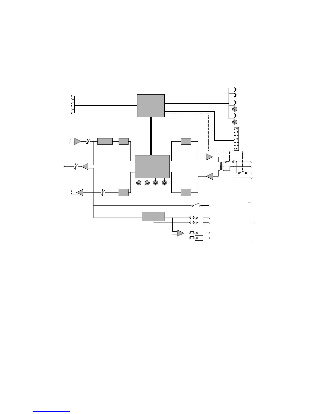
1) Refer to Figure 6 for the
Reference Variable
positions of the configurable
jumpers. Note that if the TH1
J11J11
DC Bypass Jumper
J7
Threshold
In/Out
J10
Priority
J8
Threshold
Send
is being used in the standard
setup, no changes from the
factory configuration will be
Auto
Disconnect
Position
RUN RUN
Manual
Disconnect
Position
OUT IN OUT IN OUT
OUT
IN
IN
necessary.
2) Connect the telephone line to
the LINE input RJ-11 jack. If a
local telephone is to be used in
conjunction with the TH1,
F
R
N
connect it to the PHONE input
T
RJ-11 jack. Note that to
originate calls, a local phone
must be connected to the
system.
3) Connect the Aux Output of the
AC1 to the IN(+), IN(-), and
ground terminals of the TH1.
Pin 2 of the Aux Output should
connect to the IN(+) terminal, Pin 3 to the IN(-) terminal, and Pin 1 to GND.
4) Set the both TX LEVEL control and the RX LEVEL control to the mid position (9 o’clock). Set the Aux Output
level control on the AC1 to the mid position.
5) Set the dipswitch options as desired. Factory settings are:
Echo Suppression Auto
Auto Answer On
Setup/Operate Operate
Auto Init On
Volume Limit No Limit
6) If a local phone is connected, originate a call to a remote site. If no local phone is present, someone at a remote
site must call you. If you are the originating site, press the CONNECT button to connect the TH1 to the phone
line after the call has been established. If the remote site originates the call, and Auto Answer is On, the TH1
will establish the connection automatically.
7) Adjust the receive (near-end) volume level using the RX LEVEL control. Then adjust the transmitted level using
the Aux Output level control on the AC1.
8) When all volume levels are acceptable, disconnect the call by pressing the CONNECT button again.
9) Set the Setup/Operate dipswitch to the Operate position. If any limitation on the remote volume control range is
desired, set the Volume Limit dipswitches accordingly.
10) The TH1 revisions 1.2 and higher now include firmware support for the J11 DC Bypass jumper. This jumper can
be used to bypass the automatic disconnect circuitry on the TH1. This feature is intended to be used in
installations where the TH1 is connected to an outside phone line through a PBX system which does not supply
DC battery. By changing the position of the DC Bypass jumper, and by selecting the dipswitch option AUTO
ANSWER to OFF, the TH1 will be transfered to fully manual operation. The factory default position is Auto
Disconnect.
U11
U7
J1
J2
U6
C1
J3
RL1 T1
U2
U1 U3
U9
U8
U23
J10
J7
U25
J9
J8
U13
U12
U22
U10
U26
U24
TP1
D25
RL2
J6
D26
D27
D28
R43
R56
SW4
LINE
PHONE
J9
NOM Send
CONNECT
TX
LEVEL
RX
LEVEL
J11
RUN
Figure 6 - TH1 Configurable Jumpers
9