LedLab dled PUSH DALI User manual

PUSH DALI
Vi säljer och konsulterar Ledbelysning
Utebelysning | Innebelysning | Led-strip | RGB | Drivdon
HUVUDKONTOR
Kungegårdsgatan 7
441 57 Alingsås
SÄLJKONTOR
Torstensviksvägen 6
439 62 Frillesås
0322-30 30 10
order@ledlab.se
www.ledlab.se Rev.Date: August 13, 2014

PUSH DALI
Push is a 4 channel constant current source solution. It caters
LED lighting applications of up to 48 (4x12) high brightness
LEDs.
Push is DALI or 0-10V controllable.
Push allows the exibility needed in driving your high bright-
ness LEDs.
Push is a common positive LED output.
Push can come at dierent driving current versions: 350/ 500/
700mA.
Push:s channels can be connected together or unied, which
allows achieving higher driving current: 1050/ 1400mA.
Dimensions 121mm x 106mm x 59mm
Protection Short circuit
Open line
Wrong wiring
Active Thermal Protection
LED power output Max. 48VDC (depends on PSU)
350/ 500/ 700mA per channel
Max. 48 LEDs 4 Channels
Power Input External power supply 24 - 48VDC
Connections Screwable terminal blocks
APPLICATIONS
Architectural Use, LED lighting eects, Theatrical and studio
lighting, Commercial and retail, Domestic and commercial use
FEATURES
DIN-Rail and infrastructure attachment
Either 0-10V / DALI Standard
Smooth fade control with continuous current output
High eciency (up to 95%)
From 1 and up to 12 serial LEDs per channel
Self diagnostic protocol
Output protections
Active Thermal protection
Easy connection and installation
Power, communication and output state LEDs indication
Common Positive compatible
Normally On
MOUNTING AND INSTALLATION
Assembly and installation:
For proper installation and subsequent operation of each Unit,
pay special attention to the following recommendations:
- Upon unpacking the product, inspect the contents of the car-
ton for shipping damages.
Do not install damaged Units.
- Ensure proper ventilation of each Unit and avoid areas where
corroding, deteriorating or explosive vapors, fumes or gases
may be present.
- Allow for proper clearance of Unit enclosure and wiring termi-
nals for easy access, hardware conguration and maintenance.
- Ensure that the Unit is securely attached, properly mounted,
and free of excessive vibration.
IMPORTANT
Ensure that power is disconnected before installing, wiring, or
servicing the Unit.
DO NOT HOT PLUG THE MAIN UNIT TO THE BASE!
-Do not attempt to install or use the Unit until you read and
understand the installation instructions and safety labels.
-Do not use the Unit if power cables are damaged.
- Unit intended for maximum operating ambient 40°C.
The instructions and precautions set forth in this user guide are
not necessarily all-inclusive, or relevant to all applications as
d-led cannot anticipate all conceivable or unique situations.

(1) Power in (24-48V)
Pin Voltage
Polarity
(-) -V
(-) -V
(+) +V
(+) +V
(2 ) 0-10V Input
Pin Designation
0-10V 0-10V
COM COM
(3 ) DALI input
Pin Designation
- DA DALI
+ DA DALI
1050/1400mA wiring:
In order to connect 1050/1400mA xtures to
Push ch annels 1-2 and 3-4 must be wired to-
gether as follows:
Maintain correct polarity when connecting the LEDs. Failure to do so may cause damage to the LEDs (especially at low number of
serried LEDs per channel)
If the NTC sensor is not connected, Thermal Protection will be disabled for the Output.
UNIT CONNECTION

Power Wiring
- Please follow the PSU selection guidelines below in order to
select the correct Power Supply.
- Use at least 18 AWG (0.75mm2) for DC Power In connection.
- It is highly recommended to connect all 4 terminals of the
Power In screw terminal block.
Important
Maintain correct polarity when connecting the Power Supply.
Failure to do so may cause damage to the Unit.
PSU selection guidelines
The PSU must be selected while considering the maximal num-
ber of serried LEDs per channel in the application, output cable
type/length and the power rating needed to drive the LEDs at
the desired current.
Below is a table that illustrates the relationship between the
variables
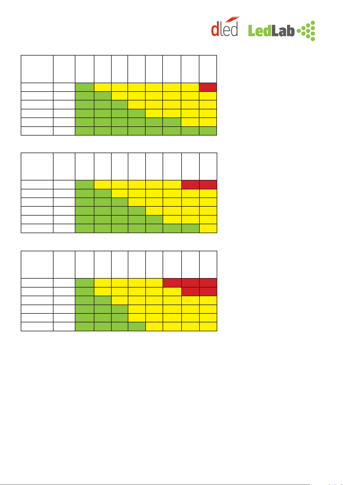
PSU selection table for High-Power LED xtures
The calculations were made assuming the following conditions:
- All 4 channels are equally loaded.
- 15% power was added to the nominal ratings as a minimal com-
pensation reserve for system eciency and drop voltage on the
output line.
The values presented in the tables of this section are general
guidelines only, and as such should be used with caution. Always
check the specications of the LED xtures used as a load and
conrm whether the conditions stated above satisfy the needed
requirements.
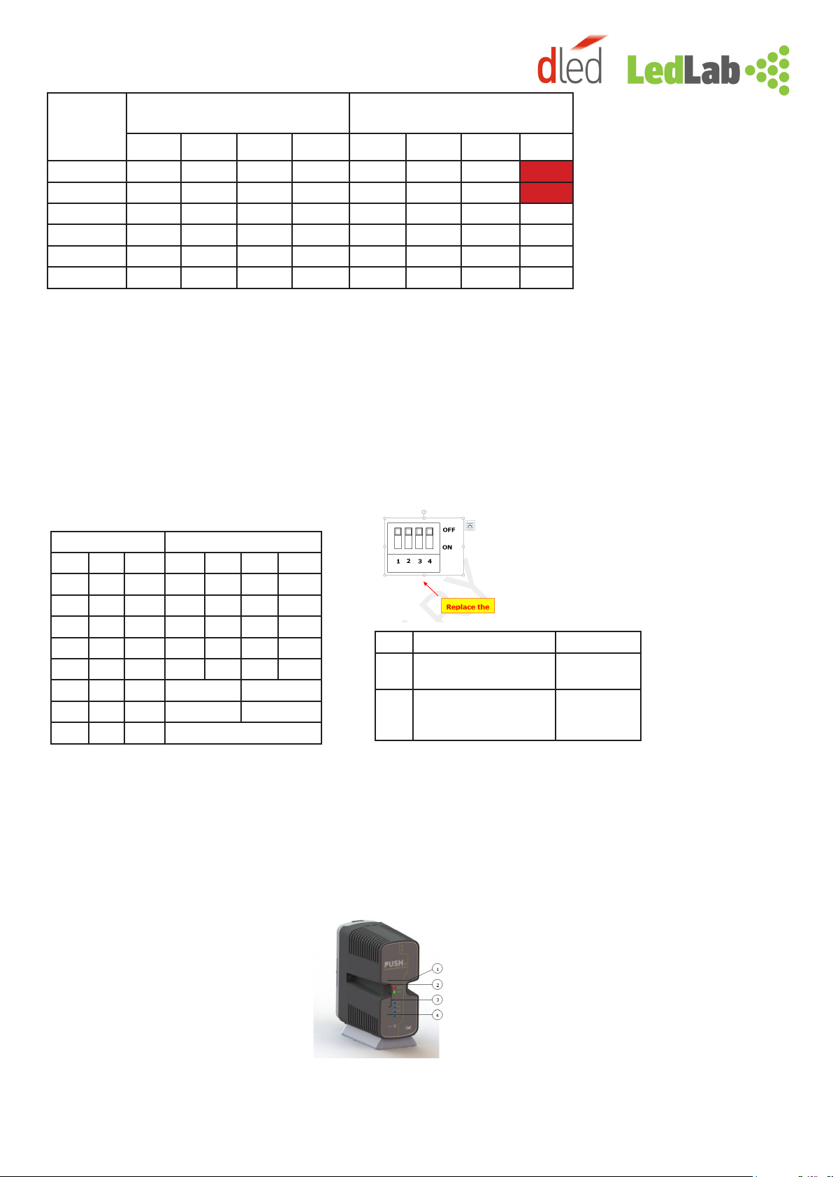
PSU selection table for COB LED xtures
The calculations were made assuming the following conditions:
- All 4 channels are equally loaded.
- 15% power was added to the nominal ratings as a minimal com-
pensation reserve for system eciency and drop voltage on the
output line.
- Red color means that the specied COB chain cannot be used
(due to high Vf).
The values presented in the tables of this section are general
guidelines only, and as such should be used with caution. Always
check the specications of the LED xtures used as a load and
conrm whether the conditions stated above satisfy the needed
requirements.
Numbers
of LEDs in
series per
channel
Total Vf
of LEDs
(typ.)
Recommen-
ded PSU
Voltage
Minimal PSU power
rating for PUSH
350mA 500mA 700mA
13,5V 24V 5,6W 8,1W 11,3W
2 7V 24V 11,3W 16,1W 22,5W
3 10,5V 24V 16,9W 24,2W 33,8W
6 21V 24V 33,8W 48,3W 67,6W
9 31,5V 48V 50,7W 72,5W 101,4W
12 42V 48V 67,6W 96,6W 135,2W
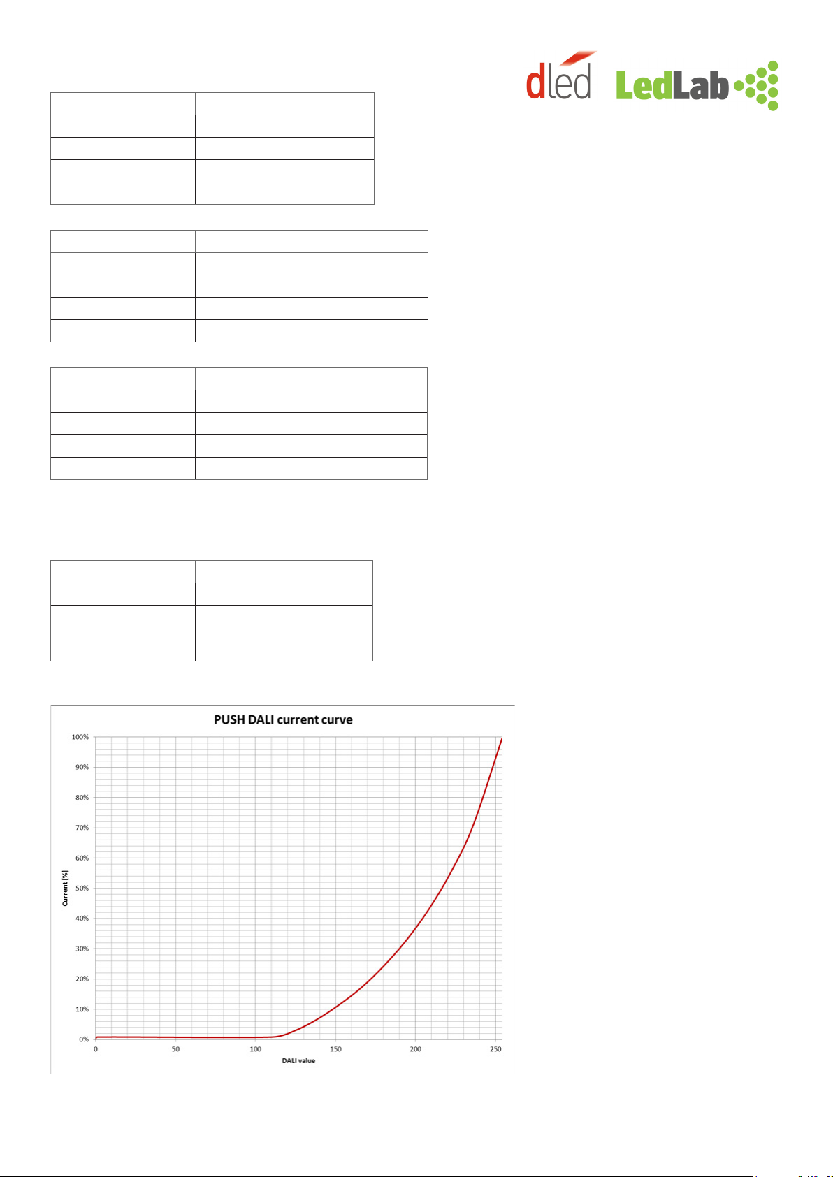
Numers
of COB
xtures in
series per
channel
Rated
power
of COB
Total Vf of COB Recommended
PSU Voltage
Minimal
PSU
power
rating for
PUSH
1050mA 1400mA 1050mA 1400mA
1
10W 9,5V 7,1V 24V 24V 23W
15W 14,3V 10,7V 24V 24V 35W
20W 19,0V 14,3V 24V 24V 46W
25W 23,8V 17,9V 48V 24V 58W
2
10W 19,0V 14,3V 24V 24V 46W
15W 28,6V 21,4V 48V 48V 69W
20W 38,1V 28,6V 48V 48V 92W
25W X 35,7V X 48V 115W
310W 28,6V 21,4V 48V 48V 69W
15W X 32,1V X 48V 104W

Cable type / length limitations for different LED loads:
At driving current 350mA
At driving current 500mA
AWG Copper Drop
voltage
(100m.
350mA
Max
LEDs
50 m
Max
LEDs
100m
Max
LEDs
150m
Max
LEDs
200m
Max
LEDs
250m
Max
LEDs
300m
Max
LEDs
400m
Max
LEDs
500m
26 9,6V 12 10 9 8 7 5 3 X
24 6,1V 12 12 11 10 9 8 6 5
22(0,34mm2)3,8V 12 12 12 11 11 10 9 8
20 (0,5mm2) 2,5V 12 12 12 12 11 11 10 10
18 (0,75mm2)1,6V 12 12 12 12 12 12 11 11
16 (1,5mm2)0,9V 12 12 12 12 12 12 12 12
AWG Copper Drop
voltage
(100m.
500mA
Max
LEDs
25 m
Max
LEDs
150m
Max
LEDs
100m
Max
LEDs
150m
Max
LEDs
200m
Max
LEDs
300m
Max
LEDs
400m
Max
LEDs
500m
26 13,8V 12 11 9 7 5 1 X X
24 8,7V 12 12 11 10 8 6 3 1
22(0,34mm2)5,4V 12 12 12 11 10 9 7 8
20 (0,5mm2)3,5V 12 12 12 12 11 10 9 8
18 (0,75mm2) 2,4V 12 12 12 12 12 11 11 10
16 (1,5mm2)1,4V 12 12 12 12 12 12 12 11
At driving current 700mA
AWG Copper Drop
voltage
(100m.
700mA
Max
LEDs
25 m
Max
LEDs
50m
Max
LEDs
100m
Max
LEDs
150m
Max
LEDs
200m
Max
LEDs
300m
Max
LEDs
400m
Max
LEDs
500m
26 19,3V 12 10 8 5 3 X X X
24 12,1V 12 11 10 8 7 3 X X
22(0,34mm2)7,6V 12 12 11 10 9 7 5 3
20 (0,5mm2) 5V 12 12 12 11 10 9 8 6
18 (0,75mm2)3,3V 12 12 12 11 11 11 10 10
16 (1,5mm2)1,9V 12 12 12 12 11 11 10 9
All max. LEDs’ values are per channel.
- Green color means that full load can be used at the specied cable type / length.
- Yellow color means that only a limited amount of load may be used at the specied cable type / length as stated in the relevant row /
column.
- Red color means that the specied cable type / length cannot be used.
- The calculations are true when 48V PSU is used.
The values presented in the tables of this section are general guidelines only, and as such should be used with caution. Always check
the specications of the LED xtures used as a load and conrm whether the conditions stated above satisfy the needed require-
ments.
* Wires thicker than 1.5mm2/16AWG cannot be inserted directly into the Unit’s output terminal blocks. Use additional intermediate
terminal blocks suited for a thicker wire cross section to extend the output line.

At driving currents 1050/1400mA
Red color means that the specied cable type / length cannot be used.
The calculations are true when 48V PSU is used. The values presented in the tables of this section are general guidelines only, and as
such should be used with caution. Always check the specications of the LED xtures used as a load and conrm whether the condi-
tions stated above satisfy the needed requirements.
* Wires thicker than 1.5mm2/16AWG cannot be inserted directly into the Unit’s output terminal blocks. Use additional intermediate
terminal blocks suited for a thicker wire cross section to extend the output line.
AWG
COPPER Drop voltage at 1050mA for a line length Drop voltage at 1400mA for a line lenght
25m 50m 100m 200m 25m 50m 100m 200m
26 7,2V 14,4V 28,9V X 9,6V 19,3V 38,5V X
24 4,5V 9,1V 18,1V 36,4V 6,1V 12,1V 24,2V X
22 (0,34mm2) 2,9V 5,7V 11,4V 22,9V 3,8V 7,6V 15,2V 30,5V
20 (0,5mm2)1,9V 3,7V 7,4V 14,9V 2,5V 5V 9,9V 19,8V
18 (0,75mm2) 1,2V 2,5V 5V 9,9V 1,7V 3,3V 6,6V 13,2V
16 (0,1,5mm2)0,7V 1,4V 2,8V 5,7V 1V 1,9V 3,8V 7,6V
UNIT SETUP AND OPERATION
Dip-Swith settings
IMPORTANT!
DO NOT HOT PLUG THE MAIN UNIT TO THE BASE!
Upon power up (at any mode) the Unit shall perform a short self-test sequence:
Channels 1-4 shall briey ash.
DEVICE OVERVIEW
1 . Power status indication LED
2 . Communication status indication LED
3 . Output channels status indication LEDs
4. Mode Button
DIP SW MODE Rated Current (mA)
DP1 DP2 DP3 CH1 CH2 CH3 CH4
OFF OFF OFF 350 350 350 350
ON OFF OFF 500 500 500 500
OFF ON OFF 700 700 700 700
ON ON OFF 350 500 500 500
OFF OFF ON 500 700 700 700
ON OFF ON 1050 1050
OFF ON ON 1400 1400
ON ON ON 700 (one channel)
DP4 DALI 1-10V
OFF Upon Loss of DALI signal -
all channels at 100%
N/A
ON Upon Loss of DALI signal -
all channels at 0
Enable Ex-
ternal Analog
0-10V

LEDs INDICATION
CH1-CH4 LEDs Description
OFF Channel dimmer value = 0
ON Channel dimmer value > 0
Pulse Channel open-circuit
Fast blink Channel short-circuit
Power LED Description
ON Power is on, normal operation
Fast blink PSU voltage is out of range
Pulse Unit overheat
Double Pulse Fixture Overheat (External VTC sensor)
Communication LED Description
OFF No DMX512 signal detected
Blink DMX512 signal present
Fast blink No DALI signal detected
Fast blink - freeze blink DALI signal present, recieved new data
RESET BUTTON
Press duration Function
Short press Software reset (0-1 sec.)
Long press Short self-test, each channel
briey fades in and out one
after another (>1sec)
DALI CURRENT CURVE
The DALI current curve of Push is optimized
to accommodate proper function with most
standard DALI systems (such as Lutron),
meaning it responds as a ballast would:
- At DALI value ‘0’ the LEDs are OFF.
- At values ‘1~110’ the output shall be at mini-
mal level (around 1% of the nominal current).
- At values >110 the output shall be according
to current curve chart.
The current curve may be altered upon
special request.

ELECTRICAL
Specication Notes/conditions Value
Input Voltage Via external stabilized power supply 24~48VDC
Rated output power 48V
24V
Max. 120W total
Max. 60W total
Output voltage Depends on PSU 2~48VDC
Driving current Per channel (350, 500, 700)mA x 4 channels
(1050, 1400)mA x 2 channels
Output channels
conguration
1-4 channels
Channel driving
Capabilities (Hi-Power LEDs)
Dependant on Input Voltage and Vf
of the LEDs
Min. 1 LED per channel
Max. 12 LEDs per channel
Total driving
Capabilities (COB LEDs)
At 48V/1050mA
At 48V/1400mA
Max. 6x10W or 4x20W COB LEDs total
Max. 6x15W or 4x25W COB LEDs total
INTERFACE
Specication Option 1 Option 2
Control Method Analog 0-10V (controller must provi-
de current source)
DALI
Working Mode 0-10V (4 channels work as a single
channel)
DALI (1, 2 or 4 channels work syncroniously or sepa-
rately)
Loss of Input Signal All channels OFF Preserves previous state on all outputs, failure indi-
cation on front LEDs
CONNECTIONS
Specication Value
Power In Connection Type Screw terminal block, 4 contacts, pitch 5mm
Wire range: 22-14AWG/2.5mm2
DALI/0-10V Connection Type Screw terminal block, 2 contacts, pitch 3.5mm
Wire range: 26-16AWG/1.5mm2
Output Connection Type Screw terminal block, 10 contacts, pitch 3.5mm
Wire range: 26-16AWG/1.5mm2
PROTECTION
Specication Value
Fixture Protection Open line
Short line
Fixture Protection Active Thermal Protection*, triggered at >75°C on NTC, regulates output current according
to xture temperature
Device Thermal Protection Intrenal circuitry overheat protection:
- thermal protection under poor ventilation conditions (internal circuitry temperature
>70°C), regulates output current according to internal temperature
- lowers current on all channels to 10% at extreme thermal conditions (internal circuitry
temperature >85°C), resets after power cycle
* If the NTC sensor is not connected, thermal protection for the xture will be disabled

ENVIRONMENT
Specication Value
Ingress Protection IP20
Operating Ambient temp. Range: -18°C ~ +40°C , (0°F ~ +104°F)
Storage temp. Range: -18°C ~ +60°C (0°F ~ +140°F)
TROUBLESHOOTING
The following table provides corrective actions for possible trouble situations. If further assistance is reqired, please contact a d-led
costomer service representative.
PUSH DALI/0-10V Troubleshooting table
Trouble Possible cause(s) Corrective action
Device does not function,
power LED is OFF
Unit is not receiving power from the
external DC Power Supply
Verify POWER IN connections.
Ensure PSU’s AC circuit breaker is not tripped.
Device not responding to 0-10V
input signal (COM LED on devi-
ce’s front is blinking constantly)
Unit is not in 0-10V Mode Check DIP-Switch settings, make sure switch #4 is set
to ON (down) position
Bad 0-10V wiring or 0-10V signal is
missing
Check 0-10V wiring, make sure it’s wired to 0-10V (and
not DALI) input and the polarity is correct.
When Unit is receiving correct 0-10V signal the green
COM LED on the device will be lit on.
The 0-10V controller is of incompati-
ble (current sink) type
Check the specications of your 0-10V controller. Push
DALI/0-10V is compatible with current source control-
ler types only!
Device not responding to DALI
input signal
Bad DALI wiring or DALI signal is
missing
Check DALI wiring, make sure it’s wired to DALI (and
not 0-10V) input.
When Unit is receiving correct DALI signal the green
COM LED on the device will briey ash each time a
DALI command is received.
The device is standalone (no
DALI/0-10V signal connected),
but all channels are OFF
Wrong DIP-Switch settings Check DIP-Switch settings, make sure switch #4 is set
to OFF (up) position
CH(X) LED is blinking Possible wiring problem with the X
channel (X can be 1, 2, 3 or 4).
Check the load connection for possible short-circuit or
open line.
Power LED blinking Wrong power supply voltage Check the power supply voltage; make sure it’s in the
correct range: 24-48VDC.
Power LED pulsing Unit overheat Verify proper ventilation conditions for the Unit
Power LED double-pulsing
LED xture overheat Verify proper ventilation conditions for the connected
LED xture
Short-circuit on NTC line Check the load connection for possible short-circuit.
Vi säljer och konsulterar Ledbelysning
Utebelysning | Innebelysning | Led-strip | RGB | Drivdon
HUVUDKONTOR
Kungegårdsgatan 7
441 57 Alingsås
SÄLJKONTOR
Torstensviksvägen 6
439 62 Frillesås
0322-30 30 10
order@ledlab.se
www.ledlab.se Rev.Date: August 13, 2014
CERTIFICATIONS
Certication Standards
EU Safety IEC/EN 61347-1, IEC/EN 61347-1
EMI EN 55015, EN 61547, IEC 61000-3-2/3, CFR
47 FCC Class B
US/CA Safety (Pending) ANSI/UL 1598, CSA C22.2 NO. 250.0-08
Table of contents
Popular Lighting Equipment manuals by other brands

Stahl
Stahl 6470/2 Series manual

IOTA
IOTA P-40 instruction manual

HUBBELL LIGHTING
HUBBELL LIGHTING DualLite CCEL Series quick start guide

Chauvet Professional
Chauvet Professional PVP S5 user manual

Godox
Godox KNOWLED M600 Bi instruction manual

Lightolier
Lightolier Lighting Systems Baselyte-BSL3 Specification sheet