manuals.online logo
Brands
  1. Home
  2. •
  3. Brands
  4. •
  5. IOTA
  6. •
  7. Lighting Equipment
  8. •
  9. IOTA P-40 User manual

IOTA P-40 User manual

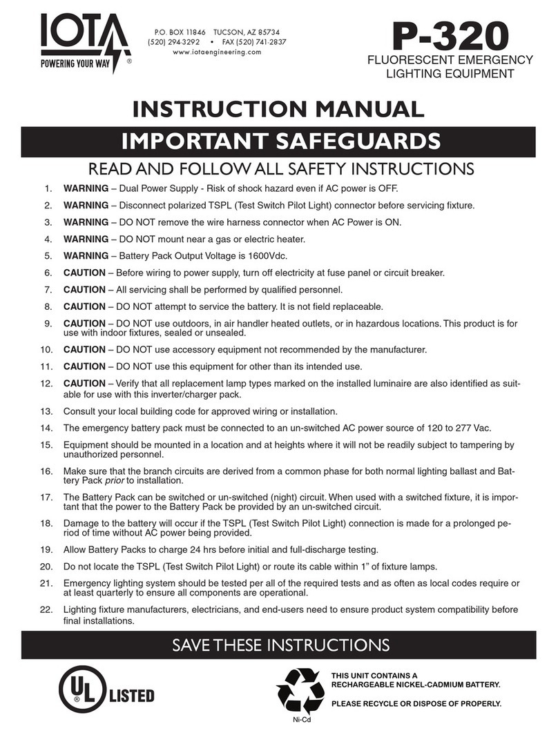
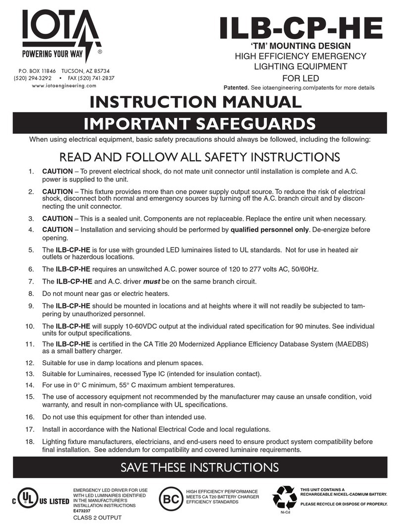
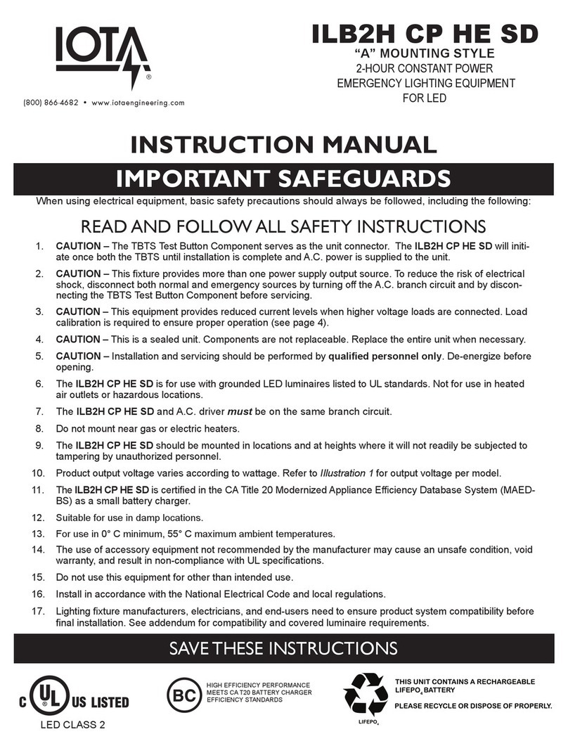
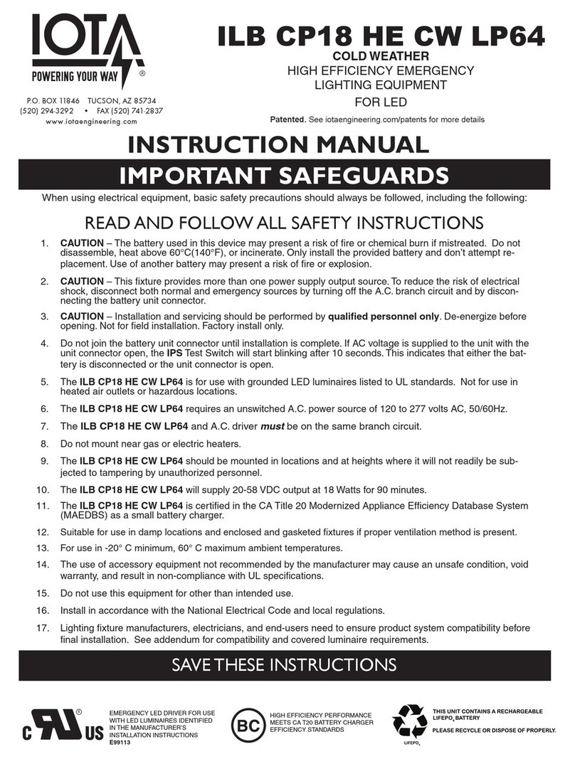
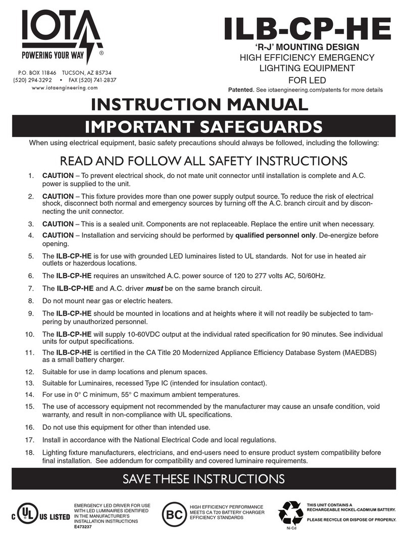
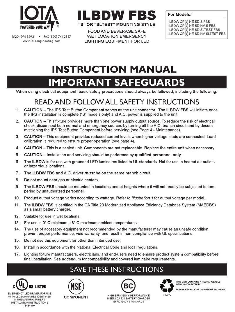
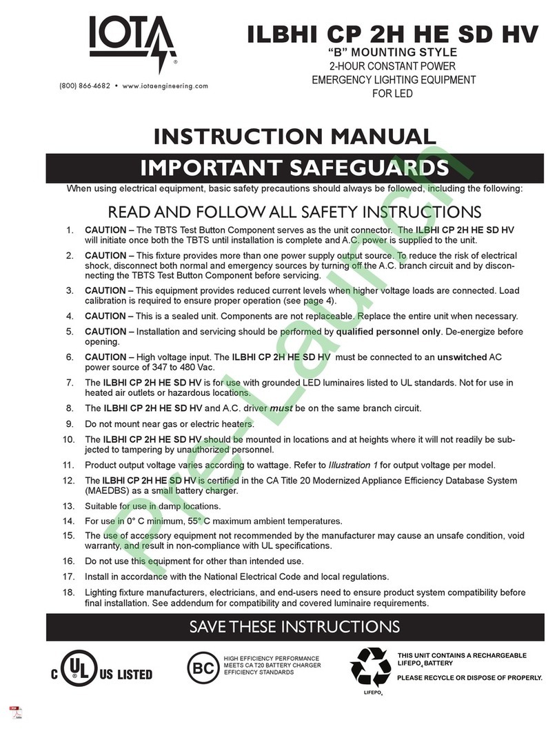
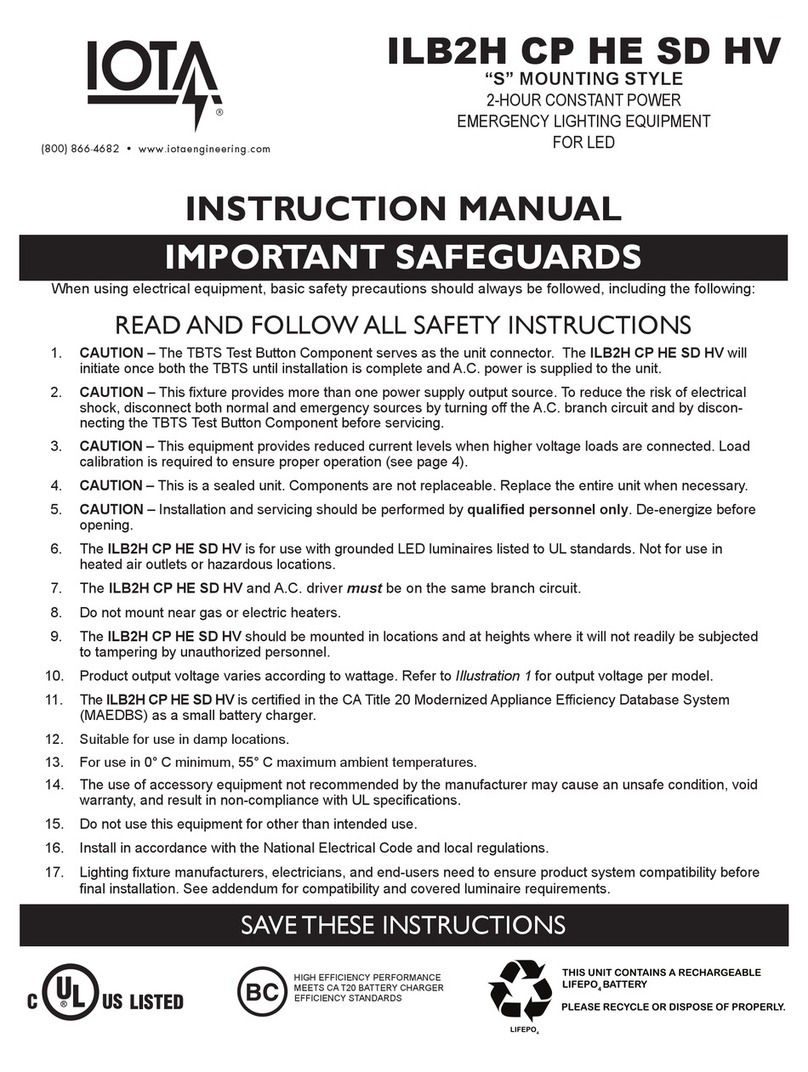
IMPORTANT SAFEGUARDS
READ AND FOLLOW ALL SAFETY INSTRUCTIONS
1. WARNING – Dual Power Supply - Risk of shock hazard even if AC power is OFF.
2. WARNING –Disconnect polarized TSPL (Test Switch Pilot Light) connector before servicing fixture.
3. WARNING –DO NOT remove the wire harness connector when AC Power is ON.
4. WARNING –DO NOT mount near a gas or electric heater.
5. WARNING –Battery Pack Output Voltage is 1600Vdc.
6. CAUTION – Before wiring to power supply, turn off electricity at fuse panel or circuit breaker.
7. CAUTION – All servicing shall be performed by qualified personnel.
8. CAUTION – DO NOT attempt to service the battery. It is not field replaceable.
9. CAUTION – DO NOT use outdoors, in air handler heated outlets, or in hazardous locations. This product is for
use with indoor fixtures, sealed or unsealed.
10. CAUTION – DO NOT use accessory equipment not recommended by the manufacturer.
11. CAUTION – DO NOT use this equipment for other than its intended use.
12. CAUTION – Verify that all replacement lamp types marked on the installed luminaire are also identified as suit-
able for use with this inverter/charger pack.
13. Consult your local building code for approved wiring or installation.
14. The emergency battery pack must be connected to an un-switched AC power source of 120 to 277 Vac.
15. Equipment should be mounted in a location and at heights where it will not be readily subject to tampering by
unauthorized personnel.
16. Make sure that the branch circuits are derived from a common phase for both normal lighting ballast and Bat-
tery Pack prior to installation.
17. The Battery Pack can be switched or un-switched (night) circuit. When used with a switched fixture, it is impor-
tant that the power to the Battery Pack be provided by an un-switched circuit.
18. Damage to the battery will occur if the TSPL (Test Switch Pilot Light) connection is made for a prolonged pe-
riod of time without AC power being provided.
19. Allow Battery Packs to charge 24 hrs before initial and full-discharge testing.
20. Do not locate the TSPL (Test Switch Pilot Light) or route its cable within 1” of fixture lamps.
21. Emergency lighting system should be tested per all of the required tests and as often as local codes require or
at least quarterly to ensure all components are operational.
22. Lighting fixture manufacturers, electricians, and end-users need to ensure product system compatibility before
final installations.
SAVE THESE INSTRUCTIONS
P-40
FLUORESCENT EMERGENCY
LIGHTING EQUIPMENT
INSTRUCTION MANUAL
P.O. BOX 11846 TUCSON, AZ 85734
(520) 294-3292 • FAX (520) 741-2837
www.iotaengineering.com
Page 2
CAUTION: Before installing, make certain A.C. power is off and the Test Switch Pilot Light (TSPL) is disconnected.
COMPONENTS
STEP 1 - WIRING TO THE LAMP AND NORMAL BALLAST
INSTALLATION INSTRUCTIONS
P-40
Quick Disconnect
Harness
Test Switch / Pilot
Light (TSPL)
If you are replacing a P-40, the wiring connections should already be made, and you can proceed to Step 2 (Mounting).
Refer to the appropriate wiring diagram below. Connect the Quick Disconnect Harness to the AC ballast and lamps as
indicated. For additional diagrams not present, contact Customer Service.
1. ONE LAMP RAPID START BALLAST
1. TWO LAMP RAPID START BALLAST
1. THREE LAMP RAPID START BALLAST
4. FOUR LAMP RAPID START BALLAST
1. ONE LAMP INSTANT START BALLAST
1. TWO LAMP INSTANT START BALLAST
1. THREE LAMP INSTANT START BALLAST
1. FOUR LAMP INSTANT START BALLAST
RED
YELLOW
YEL/BLK
RED
RED
WHITE
BLU/WHT
BLUE
WHT/RED
1LRSB
ONE LAMP RAPID START BALLAST
EMERGENCY
BALLAST
AC
BALLAST
LAMP*
BLUE
BLUE
*EMERGENCY LAMP
RED
YELLOW
YEL/BLK
BLUE
WHITE
BLU/WHT
BLUE
WHT/RED
1LISB_OUTPUT- ONLY
ONE LAMP INSTANT START BALLAST - OUTPUT ONLY
EMERGENCY
BALLAST
AC
BALLAST
LAMP*
RED
*EMERGENCY LAMP
RED
YELLOW
YEL/BLK
RED
RED
WHITE
BLU/WHT
BLUE
WHT/RED
2LRSB_OUTPUT- ONLY
TWO LAMP RAPID START BALLAST - OUTPUT ONLY
EMERGENCY
BALLAST
AC
BALLAST
LAMP*
LAMP
YELLOW
YELLOW
BLUE
BLUE
*EMERGENCY LAMP
RED
YELLOWBLUE
YEL/BLK
BLUE
WHITE
BLU/WHT
BLUE
WHT/RED
2LISB_OUTPUT- ONLY
TWO LAMP INSTANT START BALLAST - OUTPUT ONLY
EMERGENCY
BALLAST
AC
BALLAST
LAMP*
LAMP
RED
*EMERGENCY LAMP
RED
YELLOW
YEL/BLK
BLUE
BLUE
WHITE
BLU/WHT
BLUE
WHT/RED
3LRSB_OUTPUT- ONLY
THREE LAMP RAPID START BALLAST - OUTPUT ONLY
EMERGENCY
BALLAST
AC
BALLAST
LAMP
LAMP*
LAMP
RED
RED
BLU/WHT
BLU/WHT
YELLOW
YELLOW
*EMERGENCY LAMP
RED
YELLOWBLUE
BLUE
YEL/BLK
BLUE
WHITE
BLU/WHT
BLUE
WHT/RED
3LISB_OUTPUT- ONLY
THREE LAMP INSTANT START BALLAST - OUTPUT ONLY
EMERGENCY
BALLAST
AC
BALLAST
LAMP
LAMP*
LAMP
RED
*EMERGENCY LAMP
CONNECT BLACK AND ORANGE LEADS
TOGETHER IF ORANGE WIRE IS PRESENT
RED
YELLOW
YEL/BLK
RED
RED
BLU/WHT
BLU/WHT
BLUE
BLUE
WHITE
BLU/WHT
BLUE
WHT/RED
4LRSB
FOUR LAMP RAPID START BALLAST
AC
BALLAST
LAMP
LAMP
LAMP
LAMP*
YELLOW
YELLOW
BROWN
BROWN
*EMERGENCY LAMP
EMERGENCY
BALLAST
RED
YELLOW
YEL/BLK
BLUE
WHITE
BLU/WHT
BLUE
WHT/RED
4LISB_OUTPUT- ONLY
FOUR LAMP INSTANT START BALLAST - OUTPUT ONLY
EMERGENCY
BALLAST
AC
BALLAST
LAMP
LAMP
LAMP*
LAMP
YELLOW
YELLOW
*EMERGENCY LAMP
RED
RED
BLUE
LAMP COMPATIBILITY TABLE
Lamp Type Lamp Wattage Emergency Operation
T5
T8
T9
T12
PL
2’ - 4’
U LAMP
2’ - 4’
5’ - 8’
HO - 8’
16 - 31W
17 - 32W
40 - 59W
86W
One or Two Lamp
One or Two Lamp
One Lamp
One Lamp
One Lamp
One Lamp
One Lamp
One Lamp
One Lamp
One Lamp
CIRCLINE
U LAMP
2’ - 4’
5’ - 8’
HO 2’ - 4’
HO 5’ - 8’
VHO 2’ - 4’
VHO 5’ - 8’
Long Compact
(2G11)
20 - 40W One Lamp
One or Two Lamp
One or Two Lamp
14 - 28W
24 - 54W
50 - 75W
35 - 60W
70 - 110W
74 - 115W
135 - 215W
18 - 40W
34 - 40W
20 - 40W
One Lamp
One Lamp
Page 3
FIXTURE
TSPL
LUMINAIRE HOUSING
STEP 2 - MOUNTING THE P-40
STEP 3 - INSTALLING THE TEST SWITCH PILOT LIGHT (TSPL)
RED
WHITE NEUTRAL
120/277 LINE
UNSWITCHED
BLACK
YELLO
W
YEL/BL
K
BLU/WHT
BLU
E
W
HT
/
RED
EMERGENCY
BALLAST
A. Position the P-40 in the fixture wireway and fasten securely through the Mounting Slots. If necessary, drill holes and
mount with sheet metal cutting screws (not provided).
B. Fully plug the Quick Disconnect Harness into the P-40 Quick Disconnect Port. Inspect that the Harness is squarely
seated against the P-40 housing.
C. Attach the flat wire tie holder to the fixture channel. Insert a wire tie into the wire tie holder and pull the wire tie tight
around the wires extending from the Quick Disconnect Harness. This will help prevent the Quick Disconnect Harness
from being disengaged. Inspect that the Quick Disconnect Harness is still fully plugged in to the P-40 Port.
A. Locate a suitable location for the TSPL and cable that is at least 1” from the fixture lamps and is visible outside the fixture.
Drill or punch a 1/2” diameter hole in the fixture wall or wireway cover. Insert the TSPL into the hole so that the LED test
button/pilot light is located outside of the fixture.
B. Slide the TSPL Mounting Clip firmly to lock and secure the TSPL assembly.
DO NOT CONNECT THE TSPL PLUG AT THIS TIME
STEP 4 - WIRING THE AC INPUT
The P-40 requires an unswitched AC input of 120/277 volts. Connect the BLACK wire to the 120/277 Line, and the WHITE
wire to the Neutral.
COMPLETING INSTALLATION
A
A
B
B
C
P-40
Page 4
Rev. 1900
68340-000
TESTING & MAINTENANCE
Pressing the TSPL turns off the light on the TSPL and forces the unit into emergency mode, interrupting power to the designated
A.C. ballast. The emergency lamp is now being lit by the P-40 unit. After releasing the TSPL, the fixture returns to normal operation
after a momentary delay.
Initial Testing – Allow the unit to charge approximately 2 hours, then press the TSPL to conduct a short discharge test. Allow a 24
hour charge before conducting a one hour test.
The P-40 is a maintenance free unit, however, periodic inspection and testing is required. NFPA 101, Life Safety Code, outlines the
following schedule:
Monthly – Insure that the TSPL is illuminated. Conduct a 30 second discharge test by depressing the TSPL. One lamp should oper-
ate at reduced output.
Annually – Insure that the TSPL is illuminated. Conduct a full 1½ hour discharge test. The unit should operate as intended for the
duration of the test.
“Written records of testing shall be kept by the owner for inspection by the authority having jurisdiction.”
SERVICING SHOULD BE PERFORMED BY QUALIFIED PERSONNEL.
Consult Customer Service or visit www.iotaengineering.com for current warranty information.
OPERATION
Normal Mode – A.C. power is present. The A.C. ballast operates the fluorescent lamp(s) as intended. The P-40 is in the standby
charging mode. The TSPL will be lit providing a visual indication that the battery is being charged.
Emergency Mode – The A.C. power fails. The P-40 senses the A.C. power failure and automatically switches to the Emergency
Mode. One lamp is illuminated, at reduced output, for a minimum of 90 minutes. When the A.C. power is restored, the P-40 switches
the system back to the Normal Mode and resumes battery charging. See page 1 of the Instruction Manual.
TROUBLESHOOTING
Problem Possible Cause
Emergency Lamp does not op-
erate when the TSPL Button is
pressed.
TSPL Charging LED
not on
Fixture does not operate in the
Normal Mode
1. Wiring to the lamp(s) is incorrect.
2. Lamp(s) are not inserted correctly.
3. Battery has not been charged for at least 1 hour.
4. TSPL is not inserted properly into the unit.
1. AC Power is Off
2. TSPL not inserted properly into the unit.
3. The wrong test accessory is being used.
1. Battery is not fully charged.
2. Wrong type or number of lamps connected
3. Battery is at end of life.
1. Wiring to the lamp(s) or normal ballast is incorrect.
2. Lamp(s) are not inserted correctly.
3. Lamp(s) are at end of life
4. AC power is off to the normal ballast (uses fixture switch)
Emergency Ballast does not
operate lamps in the emergen-
cy mode for at least 90 minutes.
STEP 5 - APPLY AC POWER AND CONNECT THE TSPL
A. Apply continuous AC power to the P-40, then connect and fully engage the TSPL Connector to the P-40. Insure the
TSPL connector latch is properly seated in the recess slot on the P-40 housing. Ensure that continuous AC power
has been applied to the P-40 before connecting the TSPL, or you will begin to drain the P-40 batteries and may hinder
proper emergency operation.
B. Verify that the TSPL light is on, then mark the TSPL location on the fixture with the TSPL label.
Caution: fixture contains live wires during
this portion of installation. Use insulated
gloves and tools
Other IOTA Lighting Equipment manuals

IOTA ILBLP CP HE SD User manual

IOTA

IOTA ILBLP CP HE SD User manual

IOTA ILB CP07 HE User manual

IOTA

IOTA ILB CP07 HE User manual

IOTA ILB-CP20-HE-SD-S User manual

IOTA

IOTA ILB-CP20-HE-SD-S User manual

IOTA D Series User manual

IOTA

IOTA D Series User manual

IOTA P-320 User manual

IOTA

IOTA P-320 User manual

IOTA ILBHI CP 2H HE SD HV User manual

IOTA

IOTA ILBHI CP 2H HE SD HV User manual

IOTA ILBLP SP18 HE SD LC CW User manual

IOTA

IOTA ILBLP SP18 HE SD LC CW User manual

IOTA P-32 User manual

IOTA

IOTA P-32 User manual

IOTA ILB CP18 HE CW LP64 User manual

IOTA

IOTA ILB CP18 HE CW LP64 User manual

IOTA ILBHI CP HE SD HV User manual

IOTA

IOTA ILBHI CP HE SD HV User manual

IOTA ILB-LP-CP-HE-SD-HV User manual

IOTA

IOTA ILB-LP-CP-HE-SD-HV User manual

IOTA TBTS Series User manual

IOTA

IOTA TBTS Series User manual

IOTA ILB-CP-HE-SD-XB User manual

IOTA

IOTA ILB-CP-HE-SD-XB User manual

IOTA ILB CP20 HE AELR HV User manual

IOTA

IOTA ILB CP20 HE AELR HV User manual

IOTA ILBLP SP HE SD LC CW User manual

IOTA

IOTA ILBLP SP HE SD LC CW User manual

IOTA I-320 User manual

IOTA

IOTA I-320 User manual

IOTA ILBDW FBS User manual

IOTA

IOTA ILBDW FBS User manual

IOTA ILBLP CP HE SD LC CW User manual

IOTA

IOTA ILBLP CP HE SD LC CW User manual

IOTA ILB-CP Series User manual

IOTA

IOTA ILB-CP Series User manual

IOTA ILB2H CP HE SD User manual

IOTA

IOTA ILB2H CP HE SD User manual

IOTA ILBLP CP HE SD HV User manual

IOTA

IOTA ILBLP CP HE SD HV User manual

IOTA I-320-HE User manual

IOTA

IOTA I-320-HE User manual

IOTA I-42-EM-B User manual

IOTA

IOTA I-42-EM-B User manual

IOTA I-4PT-A User manual

IOTA

IOTA I-4PT-A User manual

Popular Lighting Equipment manuals by other brands

LIGMAN KWH-50002 installation manual

LIGMAN

LIGMAN KWH-50002 installation manual

Aritech DI530 Solitaire Expansion Unit MK3 installation manual

Aritech

Aritech DI530 Solitaire Expansion Unit MK3 installation manual

Dr. Mach Quintaflex R96 Directions for use

Dr. Mach

Dr. Mach Quintaflex R96 Directions for use

unios Vespa G2 Installation

unios

unios Vespa G2 Installation

Signal Mate 3NMMHDKW owner's manual

Signal Mate

Signal Mate 3NMMHDKW owner's manual

Dialog WLC-4150-C Field guide

Dialog

Dialog WLC-4150-C Field guide

Chauvet LED Mushroom user manual

Chauvet

Chauvet LED Mushroom user manual

MJ LED LIGHTNING MJ-1029A user manual

MJ LED LIGHTNING

MJ LED LIGHTNING MJ-1029A user manual

OBI Valero 205 263 quick start guide

OBI

OBI Valero 205 263 quick start guide

Commercial Electric 54263141 Use and care guide

Commercial Electric

Commercial Electric 54263141 Use and care guide

LIGMAN JET 48 installation manual

LIGMAN

LIGMAN JET 48 installation manual

Elumen8 Meteor 150 RGBW IP Pixel Batten user manual

Elumen8

Elumen8 Meteor 150 RGBW IP Pixel Batten user manual

Moda Light FLATFLEX HCRI INTERIOR Installation

Moda Light

Moda Light FLATFLEX HCRI INTERIOR Installation

Chauvet Intimidator wave irc user manual

Chauvet

Chauvet Intimidator wave irc user manual

SloanLED BendLUX 701960-6WS241 installation guide

SloanLED

SloanLED BendLUX 701960-6WS241 installation guide

LUMEN CENTER ITALIA VENDOME Assembly instructions

LUMEN CENTER ITALIA

LUMEN CENTER ITALIA VENDOME Assembly instructions

Jinbei EF-300Bi manual

Jinbei

Jinbei EF-300Bi manual

V-TAC VT-559 Installation instruction

V-TAC

V-TAC VT-559 Installation instruction

manuals.online logo
manuals.online logoBrands
  • About & Mission
  • Contact us
  • Privacy Policy
  • Terms and Conditions

Copyright 2025 Manuals.Online. All Rights Reserved.