201606 Version
INSTALLATION INSTRUCTIONS
(continued)
1. Separate the mounting bracket from the fixture
2. Line up the mounting bracket and EVA gasket in desired location and mount securely. (EVA gaskets will
provide weather-tight seal. Step 1)
3. Bring the fixture up to the mounting bracket and hook the bottom of the fixture onto the key hole slot at a
45 degree angle on the mounting bracket for hands free wiring. (Step 2)
4. Complete the wiring to the power source and ground. ( Fig .2 & 3 )
5. Bring the fixture onto an upright position and make sure the clips on the fixture slide into the key hole on
the mounting bracket. (Step 3)
6. Slide down the fixture, tighten the set screw, and make sure the fixture is securely mounted on the bracket.
(Step 4& Step 5)
PHOTOEYE INSTALLATION (IF COMING WITH PHOTOEYE)
Photocell may be installed in the field. Apply weatherproof silicone sealant to all plugs, around photocell and unused
conduit entries.
1. Remove close up plug on top of the wall mounting box.
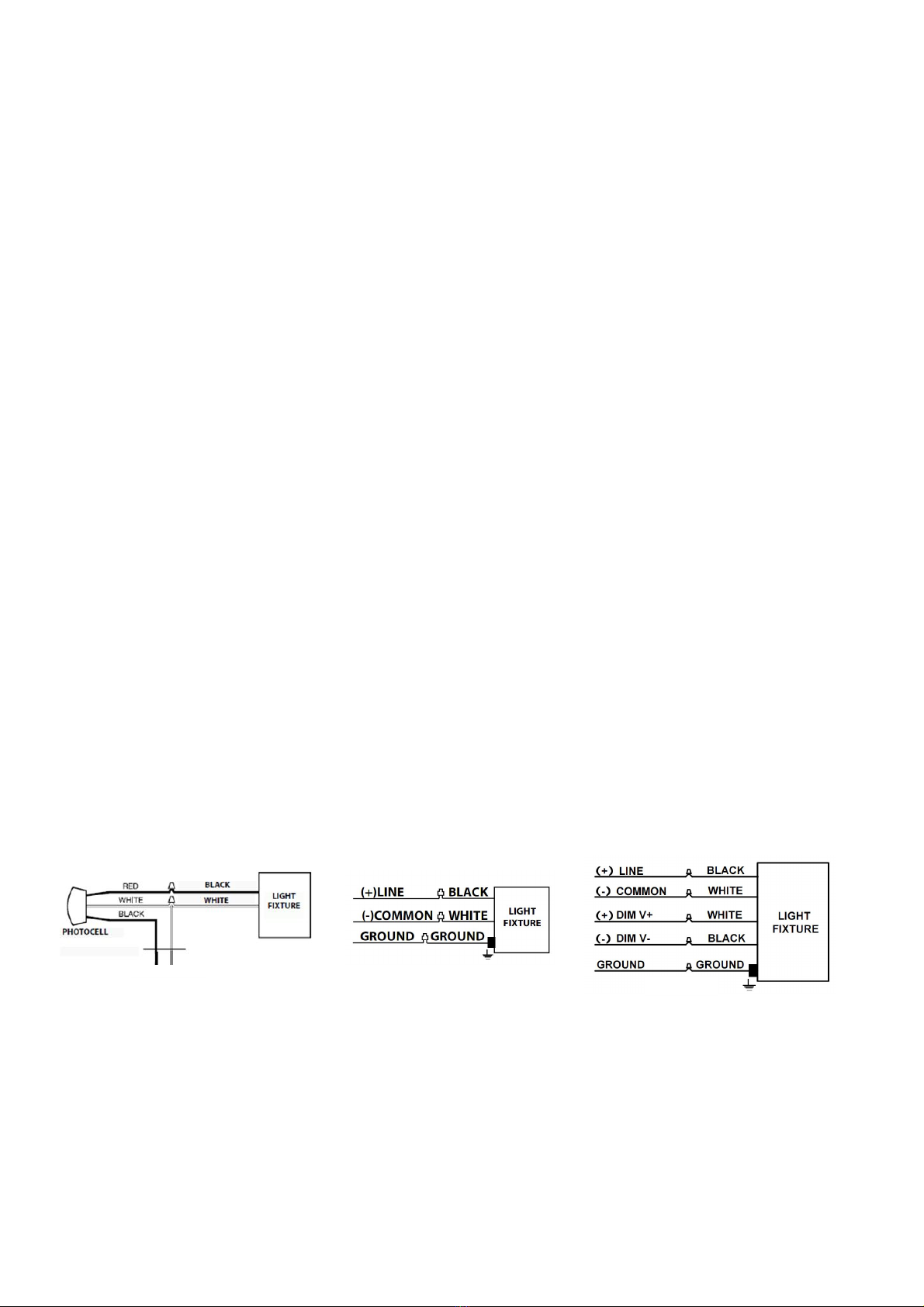
2. Install photocell and wire as per diagram Fig.1.
3. Use photocell rated for your supply voltage.
ON-OFF WIRING
Universal voltage driver permits operation at 120V thru 277V, 50 or 60 Hz. Units ordered with (/480V) suffix are 480V,
60Hz. For Non-Dimming, follow the wiring directions as in Fig. 2.
1. Connect the black fixture lead to the (+) LINE supply lead.
2. Connect the white fixture lead to the (-) COMMON supply lead.
3. Connect the GROUND wire from fixture to supply ground.
0-10V DIMMABLE WIRING
Universal voltage driver permits operation at 120V thru 277V, 50 or 60 Hz. For 0-10V Dimming, follow the wiring
directions as in Fig.3.
1. Connect the black fixture lead to the (+) LINE supply lead.
2. Connect the white fixture lead to the (-) COMMON supply lead.
3. Connect the GROUND wire from fixture to supply ground. DO NOT connect the GROUND of the dimming fixture to
the output.
4. Connect the white fixture lead to the(V+) DIM lead.
5. Connect the black fixture lead to the(V-) DIM lead.
6. The driver is coming with dimmable leads, if it is unused, make sure the leads are properly capped (If applicable).
CLEANING & MAINTENANCE
CAUTION: Be sure fixture temperature is cool enough to touch. Do not clean or maintain while
Fixture is energized.
1. Clean glass lens with non-abrasive glass cleaning solution.
2. Do not open fixture to clean the LED. Do not touch the LED
Note: These instructions do not cover all details or variations in equipment nor do they provide for every possible
situation during installation, operation or maintenance.
Fig.1 Fig.2 Fig.3


