Legend HS-808 User manual

www.legendhydronics.com
1-866-752-2055
300 N. Opdyke Rd.
Auburn Hills, MI 48326
www.legendhydronics.com
866-752-2055
HS-808
HYDRAULIC SEPARATOR
Installation Guide
Advantages of the HS-808
- Provides hydraulic separation between the primary & secondary sides of the system.
- Allows for variable system ow and xed or variable boiler ow, without pump interference between
the two sides.
- Includes a high capacity automatic air vent with service check for the removal of air from the system.
- Includes a drain valve with ¾” garden hose threads for the purging of collected dirt from the system.
- Available in up to 6 different connection types, in multiple sizes.
- Has a ½” plugged port where you could mount a thermometer and / or pressure gauge.
- Includes an aluminum embossed insulation shell and aluminum tape.
Pictured:
HS-808 with LegendConnect™
Adaptors
Pictured:
Sample System
To & From Zones
(e.g. Radiant Manifolds)
High
Eciency
Boiler
Hydraulic
Separator
w/Air Vent
and Purge
Boiler
Circulato
r
Zone
Circulators
Introduction
The HS-808 Hydraulic Separator is a multi-function device that provides hydraulic separation, air elimination
and dirt removal in a single, compact device that requires little maintenance. The HS-808 functions as a
“Bridge and a Disconnect” between a heating/cooling systems power generating unit(s) and the distribution
system. The ow pattern through the HS-808 depends on the ow rates of the primary and secondary sides
of the system. (See ow diagrams in the Size Section) The various mixing patterns internal to a hydraulic
separator create a blending of the primary and secondary ows and temperatures, thus creating a “Bridge”
between the two sides. Modern hydronic systems, especially those that contain low mass, water tube
boilers, like a Mod-Con, generally have a relatively high ow / high head pumping requirement to operate at
peak efciency on the Primary side. In contrast, the Secondary, distribution side of the system, often has a
relatively low, even variable ow, with very little pumping head. The HS-808 Hydraulic Separator provides
a “Disconnect” between these very distinct requirements on the primary and secondary sides of the system,
so that they do not interfere with each other. Hence, the “Bridge and Disconnect” benet of a hydraulic
separator.
Additional features of the HS-808 Hydraulic Separator include: Air & Debris Removal - The ows of both the
primary and secondary sides of the system go into the HS-808 where the uid velocities slow down allowing
air to rise and be vented out through a serviceable automatic air vent, and dirt particles to fall out and collect
at the bottom, ready to be purged out through the Purge Valve with standard ¾” garden hose connection.

www.legendhydronics.com
1-866-752-2055
300 N. Opdyke Rd.
Auburn Hills, MI 48326
www.legendhydronics.com
866-752-2055
HS-808
HYDRAULIC SEPARATOR
Installation Guide
Installation / Assembly
1. To install the HS-808 Hydraulic Separator, remove the Union Nut (13) and EPDM Gasket (12) from
all four connection ports and set them aside.
2. Install the adhesive insulation rings, (5) & (6) around the stub pipes of the HS-808, to prepare
for the use of the insulating shell. Remove the adhesive backing and attach each piece around the
corresponding connection size.
3. Install the system piping into the selected LegendConnect™ adaptor using standard piping
practices. (For more detailed instructions on installing the LegendConnect™adaptors, please review
the LegendConnect™ Installation Manual.)
4. After the system piping is connected to the LegendConnect™ adaptor, take the union nut (13) that
was removed in step 1, and slide it over the system pipe.
5. Insert the EPDM gasket (12) that was removed in step 1 into the union nut, and hand tighten it to
one of the HS-808 ports.
6. Repeat steps 3 thru 5 for the other three ports.
7. After all four of the LegendConnect™ adaptors have been attached, position the HS-808 in the
desired position in the system and use a wrench to tighten the union nuts. Typically no more than a ¼
turn past hand tight is needed to create a seal.
SIZING CHART
Connection Size Maximum Flow Rate Cv
1” 11 gpm *
1-1/4” 18 gpm *
1-1/2” 25 gpm *
*The pressure drop through the HS-808 is so low, the Cv is not
measurable.
1
2
6
8
4
511
10
12
13
9
3
7
HS-808 Size Selection
To select the proper size HS-808 for the project, determine the maximum ow rate for both the primary (f1) and secondary (f2) circuits, considering each of the
possible ow conditions for the system as shown in the diagrams below. Select the HS-808 connection size from the Sizing Chart below that can handle the
highest of (f1) and (f2).

www.legendhydronics.com
1-866-752-2055
300 N. Opdyke Rd.
Auburn Hills, MI 48326
www.legendhydronics.com
866-752-2055
HS-808
HYDRAULIC SEPARATOR
Installation Guide
Installation / Assembly-continued
8. The Air Vent (2) should always be installed onto the 1/4” x 1/2” Service Check Adapter (included
with the Automatic Air Vent). Thread the male end of the Service Check Adapter into the top 1/2”
port on the HS-808. Thread the 1/4” male threads of the Air Vent into the Service Check Adapter
hand tight¹ only.
9. Thread the male end of the Fill/Purge Valve (3) into a lower 1/2” port of the HS-808 until tight¹.
Orient the Fill/Purge Valve so that the handle can be operated comfortably once the HS-808 is
installed. The opposite end of the Fill/Purge Valve has a 3/4” male garden hose thread (GHT) port
and includes a brass cap with plastic tether. The plastic tether should slide over the end of the GHT
port end of the Fill / Purge Valve. The brass cap, with EPDM gasket included, should be threaded on
to the GHT port of Fill / Purge Valve until ready to use.
10. Install the insulation shell, (7) & (8) on the back side rst, then on the front side. Push the two
halves together and then use the aluminum tape (9) to seal the seams and keep the two halves of
the insulation shell together.
Note: These parts seal together and to the manifold with an EPDM gasket (o-ring). One quarter (1/4) turn beyond
“hand-tight” is normally sufcient to seal properly. If turning beyond 1/4 turn is required to align gauges and
handles then do so, up to one (1) full turn beyond “hand-tight”.
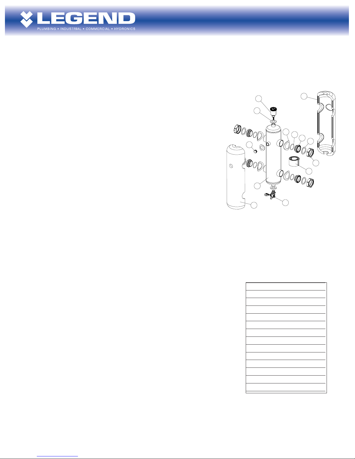
PART
1 Body
2Automatic Air Vent w/ Check
3Drain Valve w/ GHT
4 Temp. / Pressure Port Plug
5Adhesive Insulation Ring Lg (x4)
6Adhesive Insulation Ring Sm (x3)
7Insulation Shell, front
8Insulation Shell, back
9 Insulation Tape
10 O-Ring
11 MPT body adapter
12 Adapter gasket
13 Union nut
1
2
6
8
4
511
10
12
13
9
3
7
Maintenance
A. Air Vent cleaning (as recommended by system designer, typically once per year minimum) – Remove the
air vent from the 1/4” x 1/2” service check adapter by un-threading counter-clock wise, as quickly as possible.
While un-threading the air vent from the check valve, a small amount of system uid may leak (drip) out, but
should stop upon nal removal from the check valve. This is normal as the check valve mechanism does not
complete close off until the air vent is fully removed. Un-thread the cap on the air vent, counter-clock wise
and remove the internal plastic components. Rinse the plastic components with clean water to wash off any
debris. Check and rinse, as needed, any debris from within the brass air vent body prior to reinserting the plastic
components. Re-attached the air vent cap by tightly threading clock-wise onto the air vent body. Replace the air
vent back into the 1/4” female threads of the check valve, hand tight only.
B. Debris blow out (as recommend by system designer, typically within 1 week of system start-up and a
minimum of once per year thereafter) – If possible, close the isolation valves for the HS-808 to isolate it from
system pressure. If isolation valves have not been installed, the following instructions can still be followed;
however special care should be used when opening the drain valve as excessive loss of system uid may occur.
Remove the brass cap from the GHT on the drain valve. Attach a drain hose with GHT female connection to
the end of the drain valve and locate the open end of the hose in a bucket or suitable drain location. Open the
drain valve (no more than 2 seconds at a time if the HS-808 has not been isolated) to allow the debris collected
at the bottom of the HS-808 to blow out through the hose and into the bucket or suitable drain location. Once
completed, remove the hose from the drain valve and re-install the cap.
C. Check system pressure into the HS-808, slowly reapply system pressure and check for leaks. Once it’s
conrmed that there are no leaks, the system can be put back into operation. Especially if no isolation valves were
used, you may need to repeat the ll/purge procedures recommended by the system designer to replace lost uid
and repressurize the system.
Table of contents
Popular Water Filtration System manuals by other brands

Veolia
Veolia Hydrotech Drumfilter HDF - 16/20V- Value... Operation and maintenance manual

FSA
FSA GT1-23LS manual

Watts
Watts PWDWUV3 Installation, operation and maintenance manual

Danfoss
Danfoss VLT AAF006 Service manual

Pentair
Pentair OMNIFILTER OT32 installation instructions

Axeon
Axeon Hydrogen user manual