Leggett & Platt Vertex Fasteners Prostick VA0318 User manual

PROSTICK TOOL VA0318
OPERATING MANUAL
VERTEX FASTENERS
A DIV. OF Leggett & Platt
1798 SHERWIN AVE
DES PLAINES, IL. 60018 U.S.A.
PHONE: 847-768-6139
FAX: 847-769-7192
WEB: WWW.VERTEXFASTENERS.COM

1
Rev. A
Operational Instructions for Vertex Prostick Tool VA0318
Vertex Fasteners is committed to providing our customers with world-class customer
service and support. Our dedicated regional sales/service technicians are Vertex employees.
They know the product, the business, and their customers, and are there to serve you. Vertex
also has a well-trained staff of customer service, production and engineering professionals that
are ready and able to assist you.
This and other manuals are available on our website: WWW.VERTEXFASTENERS.COM
MAINTENANCE
Most problems with tools are a result of:
1. Normal wear and tear to components due to high usage.
2. Lack of proper lubrication.
3. Incorrect air pressure or air volume.
4. Dirt or water that may enter the tool via air lines.
5. Defective fasteners.
LUBRICATION
1. Vertex tools are designed for long, trouble free use with minimal in-line lubrication. (If
an in-line lubricator is used, it should be set at a minimal rate of flow.)
2. When lubricating tool, Pneumatic Fastening Tool Oil, Vertex part number VC0340 is
recommended. When oiling, a couple of drops of oil should be placed through the
airline fitting. Excess oil in tool will attract dirt, lint, preventing smooth operation. Cycle
tool to expel excess oil. Oil daily.
3. When servicing or repairing tool high grade lithium grease, Vertex part number
VH0214 is recommended.
AIR FILTER AND REGULATOR
1. The airline should always contain a filter and regulator unit to provide tool with a
constant flow of clean, dry air. Moisture and contaminates entering tool will decrease
the serviceable life of tool.
2. The regulator should be set between 70 and 90 psi (4.8 to 6.2 bar). Never operate
tool over 100 psi (7 bar).
TIPS ON EXTENDING TOOL LIFE
1. Always use Vertex brand fasteners and always use Vertex genuine parts when
replacing worn or broken parts. Generic fasteners, and parts may shorten tool life
and will void your tool warranty.
2. It’s best to use the lowest pressure (PSI) that the tool requires to drive the fastener
correctly and use this setting. Excess air pressure will reduce the life of tool.
3. Keep tool clean and dry and always use clean dry air.
4. Avoid dropping tool, a primary reason for parts replacement.

2
Rev. A
Helpful hints for field servicing tool jams
A jam is usually a fastener that has lodged between the driving blade and the nose.
SAFETY FIRST – Always disconnect tool from air supply before attempting to clear a jam or
servicing.
NOTE: refer to correct tool schematic for location of parts and correct part numbers.
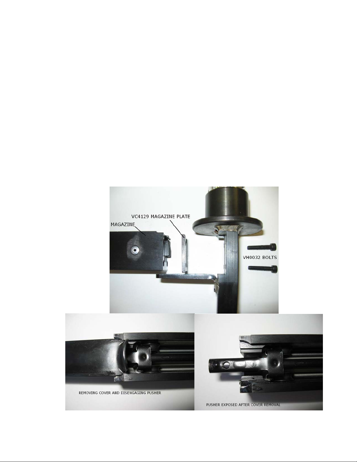
Open the magazine and remove the remaining fasteners. Some jammed fasteners may be
removed from the magazine side of the tool. Try to remove fastener with a pair of pliers.
Depending on the severity of the jam, the driver blade must be pushed back up into the tool to
allow the jammed fastener to be removed. Push the driver upwards and past the jammed
fastener. As a last resort push driver up by placing a punch at the tip of the driver and tapping
a hammer against the punch. Only strike the driver, it is the hardest part in the tool. The
driver is the only part of the tool that moves in this area. If you strike the jammed fastener, you
may cause it to jam worse in tool.
TROUBLESHOOTING
Water inside tools.
•Water inside tools is a result of natural condensation, settling in tanks and hoses. Drain
tanks and hoses daily, if possible use condensate separators in line with tools.
•Tools that have had water in them for an extended time tend to have internal
contamination and will perform poorly. Tool should be cleaned and lubricated
Tool does not fully drive fasteners.
•Air pressure too low, tools should be operated between 70 to 90 psi. (4.8-6.2 bar)
Never over 100 psi (7 bar).
•Tool not perpendicular to work surface, staples driving at angle.
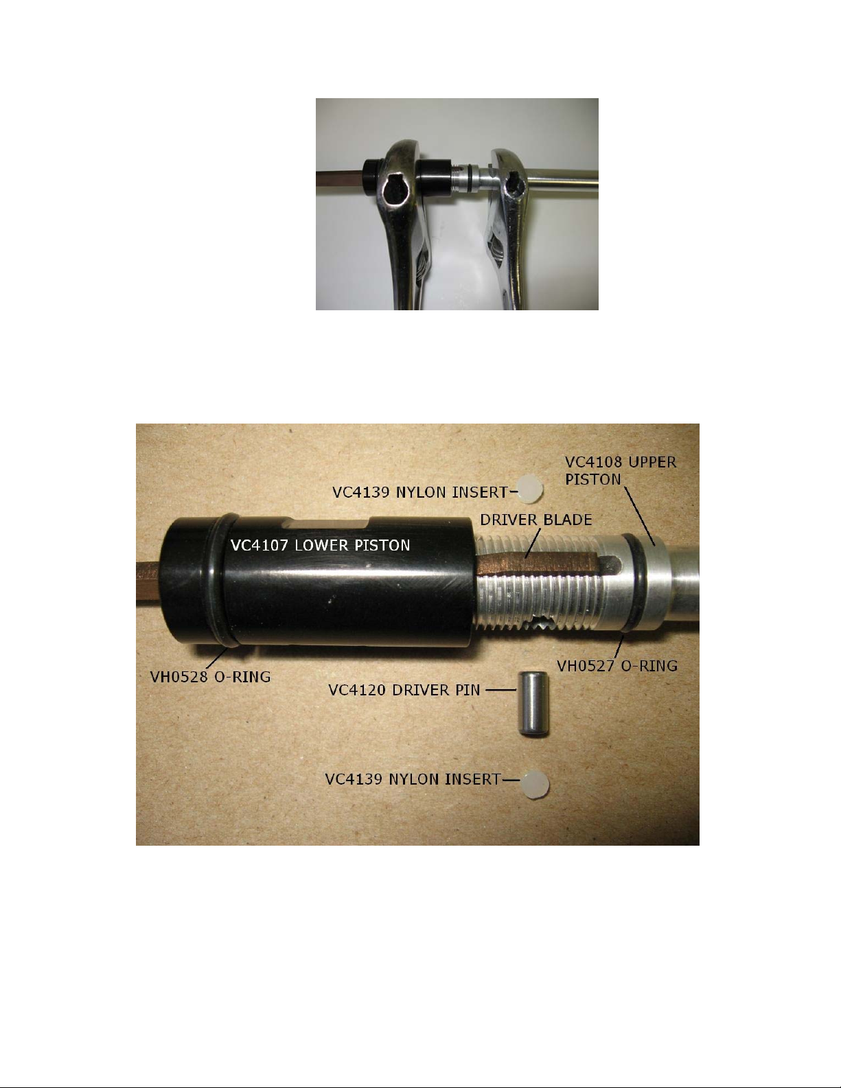
•Driver blade worn at tip. Replace driver blade VC4101.
•Piston o-rings worn or damaged. Replace o-rings upper o-ring VH0525, lower o-ring
VH0528.
•Air exhaust clogged with dirt or built up old lubricant. Clean exhaust or replace muffler
VH0545.
•Worn bumper. Replace bumper VC4119.
•Worn piston plug. Replace piston plug VC4122.
•Valve assembly worn/leaks. Replace valve assembly or components and o-rings.
•Dirt/tar build up on driver. Disassemble and clean nose/driver.
•Valve dry or dirty. Disassemble clean and lubricate.
•Air volume insufficient. Check fittings and hoses for restrictions. Restrictions can be
moisture, dirt, or hoses and fittings too small for tool volume requirements.
•Wood not fully supported under area to be stapled.
Piston/driver does not return fully.
•Bumper cracked or damaged. Replace bumper VC4119.
•Piston plug cracked or damaged. Replace piston plug VC4122.

3
Rev. A
•Piston or cylinder damaged. Replace damaged part.
•Piston o-rings worn or damaged. Replace o-rings upper o-ring VH0525, lower o-ring
VH0528.
•Air pressure too low or restricted. Check air lines/compressor. Restrictions can be
moisture, dirt, or hoses and fittings too small for tool volume requirements.
•Driver blade bent or damaged at driving end. Replace driver blade VC4101.
•Dirt/tar build up on driver. Disassemble and clean nose/driver.
•Air exhaust clogged with dirt or built up old lubricant.
•Lack of lubrication. Clean and lubricate tool, replace worn o-rings.
Tool leaks air from nose.
•Piston o-ring worn or damaged. Replace lower o-ring VH0528.
•Internal lower piston o-ring damaged. Replace o-ring VH0527.
Tool leaks air from exhaust area.
•Valve stem seal worn out. Replace valve stem seal VC4131.
•O-ring on the outside of the head valve piston worn or damaged. Replace o-ring
VH0529.
Air leak near top of tool.
•Check to make sure valve body is sealing. O-ring VH0529 must be in body enough to
seal.
•Seal on valve damaged or worn. Replace valve stem seal VC4131.
•Valve plug is loose and/or worn o-ring. Tighten or replace valve plug VC4130 and/or
replace worn o-ring VH0541.
Tool misfires.
•Firing tool too fast. Exhaust muffler may be too restrictive for operator speed. Remove
muffler VH0545.
•Pusher damaged. Replace damaged pusher VC4135.
•Pusher spring(s) weak, damaged or broken. Replace spring(s) VC4132.
•Magazine obstructed by dirt. Clean magazine, replace if worn.
•Worn bumper. Replace bumper VC4119.
•Worn piston plug. Replace piston plug VC4122
Sluggish operation.
•Lack of lubrication. Add a few drops of tool oil, Vertex part number VC0340 to air inlet
of tool. Oil daily.
•Air exhaust clogged with dirt or built up old lubricant. Clean or replace muffler VH0545.

4
Rev. A
Tool jamming.
•Burr on end of driver blade, buff burr off driver blade.
•Magazine obstructed by dirt. Clean magazine, replace if worn.
•Magazine loose. Tighten bolts VH0032.
•Pusher damaged. Replace damaged pusher VC4135.
•Pusher spring(s) weak, damaged or broken. Replace spring(s) VC4132.
•Damaged driver blade. Replace driver blade VC4101.
•Worn bumper. Replace bumper VC4119.
•Worn piston plug. Replace piston plug VC4122.
•Check fasteners are correct for tool.
Tool fails to cycle.
•Air supply restriction. Check air lines/compressor. Restrictions can be moisture, dirt, or
hoses and fittings too small for tool volume requirements.
•Tool dry, lack of lubrication. Use VERTEX air tool oil.
•Worn valve seal. Replace valve stem seal VC4131.
•Valve stuck. Disassemble/clean/check/lubricate.
Valve body loosens.
•Valve body loosens and will not stay in place. Lower bumper has taken a set and
rotates valve body. Replace bumper VC4119.
REPAIR
NOTE: Mineral spirits is recommended for cleaning tool and parts. Wipe off
immediately, dry parts thoroughly before reassembly, use adequate ventilation.
SAFETY FIRST – Always disconnect tool from air supply before attempting to clear a jam or
servicing.
NOTE: Refer to tool schematic and pictures for location of parts and correct part
numbers.

5
Rev. A
To Disassemble Valve
1. Remove valve plug VC4130 by unscrewing from valve housing. Remove spring
VH0539 and valve assembly.
2. Hold valve stem VC4123 with pliers on the small diameter area to avoid marring stem.
Unscrew flex nut VH0533 and remove washer VH0534 and VC4131 valve stem seal.
To Reassemble Valve
1. Push valve steam seal VC4131 onto valve stem followed by the washer VH0534.
2. Hold valve stem VC4123 with pliers on small diameter to avoid marring stem. Screw
flex nut VH0533 onto valve stem VC4123. Do not over tighten to point of deforming
the seal! Seal should be able to turn with effort on valve stem.
3. Insert valve stem assembly into valve housing VC4126.
4. Place spring VH0539 onto end of the valve stem assembly.
5. Replace valve plug VC4130 by screwing into valve housing VC4126 and tighten.
To Disassemble Driver Assembly
1. Remove valve housing VC4126 by unscrewing from body of tool.
2. Remove cylinder sleeve VC4105 by pulling upwards and out of body.
3. Remove piston driver assembly by pulling upwards and out of body.
4. Unscrew lower piston VC4107 from upper piston VC4108 using two wrenches as
shown.

6
Rev. A
5. Pull piston plug VC4122 out of lower piston VC4107 and off driver blade.
6. Pull lower piston VC4107 off driver blade.
7. Remove nylon inserts VC4139 and remove pin VC4120.
8. Pull Driver blade VC4101 out of upper piston.
To Reassemble Driver Assembly
1. Push driver blade VC4101 into upper piston VC4108.
2. Center Driver Pin VC4120 into hole in upper piston and driver blade followed by nylon
insert VC4139 on each side.

7
Rev. A
3. Push lower piston VC4107 onto blade and screw onto upper piston using two wrenches
until tight.
4. Push piston plug VC4122 slotted end towards piston, down blade and into lower piston
VC4107 until seated.
5. Insert the piston/driver assembly into body making sure the blade goes into the nose
and is free to move up and down.
6. Insert cylinder sleeve VC4105 into body.
7. Screw valve housing VC4126 back into body of the tool.
To Disassemble Magazine
1. Remove four (4) bolts VH0032 (5/32” Allen wrench) to remove magazine VC4136 and
magazine plate VC4129.
2. Push magazine slide VC4134 towards mounting end of magazine and remove. This
disengages the slide from the pusher VC4135.
3. Remove the springs VC4132 by unhooking them from the pusher.
4. Drive pin VH0538 from magazine (3/32” pin punch) and remove the springs VC4132.
5. Remove pin VC4133 and spring VH0537.

8
Rev. A
To Reassemble Magazine
1. Insert pin VH0538 into magazine VC4136 and thru eyelet of springs VC4132.
2. Pull springs around pulleys in magazine and attach each eyelet to pusher
VC4135. Place pusher into track of magazine.
3. Insert pin VC4133 and spring VH0537 into pocket in magazine.

9
Rev. A
4. Slide cover VC4134 into magazine, thumb hold first into mounting end as shown.
Push down on pin VC4133 compress fully to allow cover to clear. Pin will
engage into notch of cover in closed position.
5. Place magazine plate VC4128 onto end of magazine. Plate can only go on in
one direction with guide pin.
6. Place magazine assembly into nose of tool and attach with four (4) bolts
VH0032.

10
Rev. A
To Disassemble Nose
1. Remove magazine assembly as outlined above.
2. Unscrew nose VC4109 from body VC4102.
3. Remove bumper VC4119.
To Reassemble Nose
1. Replace bumper VC4119 narrow end towards blade. Blade should slide easily
into opening of bumper.
2. Orient blade so it lines up with slot of nose VC4109 and screw nose into body
VC4102.
3. Reassemble magazine to nose as outlined previously.

11
Rev. A
RECOMMENDED SPARE PARTS LIST
PART#DESCRIPTIONNOOFTOOLS
15ORMORE
VC4109DOUBLESTAPLEHEAD01
VC4119DRIVERBUMPER26
VC4120DRIVERPIN02
VC4122PISTONPLUG26
VC4124RETURNBUMPER26
VC4131VALVESTEMSEAL13
VC4132SPRING28
VC4133PIN12
VC4135PUSHER12
VC4101DOUBLESTAPLEBLADE12
VC4139NYLONINSERT26
VH0525O‐RING#11728
VH0527O‐RING#01416
VH0528O‐RING#11528
VH0529O‐RING#02404
VH0537SPRING12

VC4101 100828 DOUBLE STAPLE BLADE 1
VC4102 BC1527A BODY - STANDARD 1
VC4105 BC1530 CYLINDER SLEEVE 1
VC4107 BC1477 LOWER PISTON 1
VC4108 BC1529 UPPER PISTON 1
VC4109 100346 DOUBLE STAPLE HEAD 1
VC4119 BC1572 DRIVER BUMPER 1
VC4120 BC1478 DRIVER PIN 1
VC4122 101608 PISTON PLUG 1
VC4123 BC367 VALVE STEM 1
VC4124 BC1474 RETURN BUMPER 1
VC4125 BC283 TRIGGER 1
VC4126 BC1602A VALVE HOUSING 1
VC4129 BC1545 MAGAZINE PLATE 1
VC4130 BC156 VALVE PLUG 1
VC4131 BC442 VALVE STEM SEAL 1
VC4132 BC1260 SPRING 2
VC4133 BC34 PIN 1
VC4134 BC1537 MAGAZINE SLIDE 1
VC4135 BC694 PUSHER 1
VC4136 BC1535A MAGAZINE 1
VC4139 T34233 NYLON INSERT 2
VC4142 TRIGGER GUARD 1
VH0032 UA3816.4 SHCS, 10 - 24 x 1 4
VH0145 UA3820 SHCS, 10 - 32 x 1 1/4 1
VH0525 87137 O-RING, #117 -
VH0527 86458 O-RING, #014 -
VH0528 88998 O-RING, #115 -
VH0529 88705 O-RING, #024 -
VH0533 HN1032.5 NUT, FLEX, 10 - 32 2
VH0534 PW10.5 WASHER, #10 1
VH0537 BC41 SPRING, DETENT PIN 1
VH0538 UB2820 PIN, SPRING, 3/32 x 1 1/4 1
VH0539 T36135 SPRING, VALVE 1
VH0541 105502 O-RING, #020 -
VH0545 MUFFLER 1
VH0574 GROMMET -
VH0619 UB2808.2 PIN, ROLL, 1/8 x 1/2 -
VERTEX # BOSTITCH REF # DESCRIPTION QTY
THISDOCUMENTANDTHEDATADISCLOSEDHEREINORHEREWITHISNOTTOBEREPRODUCED,USED,OR
DISCLOSEDINWHOLEORINPARTTOANYONEWITHOUTTHEPERMISSIONOFVERTEXFASTENERSINC.
VA0318
REV DESCRIPTION BY
APPD
DATE VERTEX FASTENERS INC.
3714 JARVIS AVENUE
SKOKIE, IL 60076 U.S.A.
DWG. NO.
SCALE
DATE
APPD
DWN BY
2004
C
ECN
INVENTOR
2-25-04
A
DOUBLE SHOT
STANDARD WEIGHT
VA0318
JMW
A
NAME CHANGE
JMW 7-15-04
387
B
ADDED VC4142
JMW 5-2-05
484
C
ADDED/EDITED
NUMBERS
JMW 3-2-06
654 DA
PROSTICK
DA
VC4134
VH0538
VC4136
VH0032 VC4133
VH0537
VC4135
VC4129
VC4130
VH0539
VH0533
VH0534
VC4131
VC4123
VC4126
VC4125
VC4132
VC4105
VC4124
VC4119
VC4139
VC4120
VC4122
VC4101
VC4107
VC4108
VH0525
VH0528
VH0527
VH0529
VH0541
VC4102
VC4109
VH0533 VH0545
VH0145
VC4142
VH0574
DA
VH0619
DA
Table of contents
Other Leggett & Platt Power Tools manuals