N.KO UZ 18 Hardworker Manual

1
Bevelling Machine with Variable Angle and
Automatic Feed
NKO MACHINES
UZ 18 Hardworker
Operating and Maintenance Instructions

2
Contents
1 General information
Introduction 3
Testing 3
Guarantee 3
Identification data 4
Reference standards 5
2 Safety
Safety recommendations 6
Safety labels 7
Qualification and protection of operators 7
Safety devices 8
Residual risks 9
3 Technical specifications
Machine description 9
Technical data 10
Noise level 10
Working conditions 11
4 Installation
Transport and lifting 11
Setting and connection 12
Checking before use 13
Dismantling and disposal 14
5 Usage
Correct usage 14
Description of control devices 15
Preliminary settings 15
Bevelling 21
6 Maintenance and adjustment
Recommendations 24
Lubrication 24
Exchange of tools 25
7 Technical diagrams
Wiring diagram 28
8 Spare parts
How to order spare parts 29
Wear parts 29
Schematic drawings of spare parts and spare parts list 30 - 36

3
General information
1.1 Introduction
Thank you for purchasing one of our machines. We hope you will be fully satisfied with it.
This manual contains all the instructions for installation, adjustment, operation and
maintenance of the UZ18 Hardworker machine in conformity with valid safety standards.
The information and data in this manual are subject to change as a result of further
development of the machines. If in any doubt, please contact N.KO if you find any
deviations.
Never carry out any operations on the machine until you have read and understood the
instructions in this manual. Most accidents occurring in the workplace result from not
observing instructions and recommendations in manuals.
Graphic symbols are used in the manual to highlight important information regarding machine
safety and operation.
Attention:
Important information for the operating personnel’s safety
Important:
Instruction which must be observed to ensure correct operation of the machine
1.2 Testing
The bevelling machine is tested in our technical test room.
During the test, correct functioning of the electric system, and correct functioning of the
bevelling plates and profiles of different types and sizes are checked.
1.3 Guarantee
The Seller provides a guarantee for fault free material and workmanship of the
UZ 18 Hardworker bevelling system for a period of 5 years from the delivery date of the
goods.
A guarantee for correct functioning of the goods and materials used is provided for a period of
5 years from the delivery date of the goods.
The Seller undertakes to remove all possible defects covered by the guarantee, free of charge
and without undue delay, so that the Purchaser can use the goods appropriately. Should the
Purchaser make a claim based on a liability for defects not covered by the guarantee, s/he
shall cover the expenses incurred by the Seller.

4
The guarantee period is suspended on the day when the Purchaser notifies the Seller of a
defect covered by this guarantee, due to which the Purchaser is unable to use the goods and
makes a claim based on the liability for defects covered by the guarantee granted, until the
date when the defect is removed by the Seller.
The guarantee does not cover natural and normal wear of the goods and defects caused by
incorrect use of the goods contrary to the training and documentation provided. Further, the
guarantee does not cover defects due to overloading of the goods or those resulting from
incompetent interference in the goods or incompetent repair or modification. Incompetent
interference, repair or modification means any interference, repair or modification executed
contrary to the training or documentation provided, or executed by any person other than the
Seller or a person authorized or approved by the Seller.
Claims based on liability for defects under the guarantee granted must be made at the Seller
without undue delay after the Purchaser has found the defect; at the latest, by the end of the
guarantee period, however, otherwise these claims expire.
To make a claim based on liability for defects under the guarantee granted, the guarantee
certificate must be submitted; otherwise, the Purchaser’s claims cannot be allowed.
The Seller’s liability for defects covered by the guarantee does not arise if the defects have
been caused by passage of the risk of damage to the goods by external events. Particularly,
external events include natural disasters, force majeure, or third persons’ acts.
N.KO. considers the guarantee invalid in the event of:
- improper use of the machine;
- use contrary to national or international standards;
- incorrect installation;
- defective electrical power supply;
- serious maintenance shortcomings;
- incompetent modifications and/or interferences;
- usage of unoriginal or incorrect spare parts and equipment for the given model;
- full or partial infringement of instructions;
- exceptional events, natural or other disasters.
1.4 Identification data
The identification data of the bevelling machine are indicated on the aluminium CE label
attached to the top of the bearing housing.

5
1.5 Reference standards (CE Declaration of Conformity)

6
SAFETY
2.1 Safety recommendations
Attention:
Read the following instructions carefully to prevent personal injuries and/or property
damage.
- Never try to operate the machine unless you have carefully acquainted yourself with its
functions. If after having read this manual carefully and fully you are still in doubt, contact
the N.KO company.
- Make sure that all technical workers entrusted with operation and maintenance of the
machine are fully acquainted with all the relevant safety recommendations.
- Transport and installation of the machine can only be done by specialized workers in
conformity with the instructions in this manual.
- Before starting the machine, the operator must check that all safety devices are functional
and all safety guards are in place.
- Never use the machine for any purposes not indicated in this manual. Never process
products other than what is indicated here.
- If you want to use the machine for purposes other than those defined, ask the N.KO
company for approval.
- The machine supply voltage values are dangerous; check whether all connections are
executed correctly. Never perform any maintenance of the machine or replacement of its parts
if the machine is connected to the electrical power supply. Never install any branches on the
electrical connections.
- Replace defective parts with those recommended by the manufacturer. Never use non-
original spare parts.
- Never wear clothing or jewellery which may get caught in the moving parts. It is
recommended to use protective clothing, non-slip shoes, and protective goggles.
Important:
If during the machine lifetime any defects occur which cannot be removed with the help
of this manual, it is advisable to ask the N.KO company to resolve the problem as soon
as possible.

7
2.2 Safety labels
Safety labels are placed on the bevelling machine to protect the operators.
Meaning of the labels:
This label is placed on the electrical panel of the bevelling machine, and indicates the
presence of high voltage.
Do not remove the label from the machine.
2.3 Qualification and protection of operators
The employer is obliged to inform the operators about safety standards; moreover, he must
ensure their observance and make sure that the working area is large enough and well lit.
The term “operator” means any person who carries out installation, operation, adjustment,
maintenance, cleaning or repairs of the machine.
Attention:
Before starting work with the machine, make sure that the operator understood the
content of the operator manual.
Attention:
The operator must always:
1. Check that all safety guards are in place and safety devices are functioning before
starting the machine.
2. Avoid wearing clothes or jewellery which may get caught in moving parts.
3. Wear approved protective clothing, such as non-slip shoes, ear protectors and
protective goggles.
4. Apply safety standards; see that they are observed at all times; and, if in doubt, consult
this manual again before taking any measures.
5. Contact the machine supplier if unable to remove defects causing its malfunction, if
there are defective parts or the running is abnormal.
8
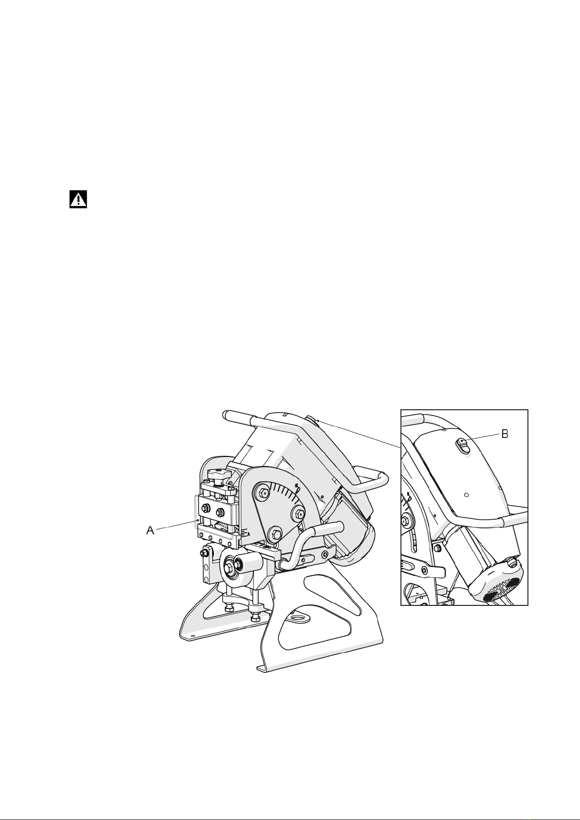
2.4 Safety devices
The machine is equipped with safety guards to isolate the zones potentially dangerous to the
operators. The guards are attached to the frame or screwed to with the machine housing. They
can be dismounted with suitable tools. This operation may be necessary during certain
maintenance activities. An acrylic glass guard is mounted in front of the cutting tool
(position A. Fig. 2.4.1) to protect the operator during bevelling.
Attention:
The guard can only be removed if the machine is at standstill, with the power supply
plug disconnected. Never use the machine without the safety guards in place.
The machine is equipped with a mushroom emergency button. This red button overrides all
other operations and stops the machine immediately (position B, Fig. 2.4.1).
Use the emergency button:
- in case of immediate danger or mechanical accident;
- for short interventions, if the machine is switched off, to perform maintenance in this state;
- the button is also equipped with a lock to prevent start of the machine by an unauthorized
person.
Fig. 2.4.1

9
2.5 Residual risks
The machine has been designed and manufactured with all devices and equipment for health
protection and the safety of operators.
The machine is fully covered to minimize the risk of contact with movable parts.
There is, however, one risk remaining:
As mentioned above, the working zone is protected as much as possible; however, it has to
remain open partly to enable feeding of the material to be bevelled.
Therefore, there is a risk of the operator putting his/her fingers into the zone in which both the
cutting tool and the work piece holder are.
Attention:
Always keep your hands as far from the cutting zone as possible.
Attention:
Always apply the safety regulations contained in this manual and ensure their
observation and the elimination of all residual risks.
TECHNICAL SPECIFICATIONS
3.1 Machine description
The bevelling machine model UZ 18 Hardworker has compact dimensions. One of its main
features is the adjustable bevel angle and automatic material feed.
The machine is equipped with a hardened cutting tool, sturdy work piece holder, direct-
reading scale used for setting values (bevel size and angle), and a special guide facilitating the
loading of material.
These characteristics enable easy setting of the working angle without exchange of the lower
cylinder, and precise regulation of the bevel angle.
The UZ 18 Hardworker bevelling machine is reliable and requires minimum maintenance.

10
3.2 Technical data
Voltage 400/480/220 V*
Frequency 50/60 Hz*
Motor power 750W,
Sheet thickness 6 ÷ 40 mm / 0.23 ÷ 1.57 in
Max. bevel width 18 mm/0.71 in (600 MPa/87 022 PSI)
Bevel angle range 15° ÷ 50°
Feed 1,9 m/min./6.23 ft/min
Dimensions 450 x 800 x 400 mm
Weight 110 kg / 242.5 lb
(*) Exact voltage and frequency values are indicated on the motor identification label.
3.3 Noise level
The machine has been designed and manufactured so that it emits the minimum noise
possible.
Measurements done at the operator’s workplace, when the machine is running in the
automatic cycle mode, ascertained these values:
- during cutting: LpA m. = 74.9 dB
LwA = 84.1 dB

11
- during unloaded operation: LpA m. = 64.5 dB
LwA = 76.4 dB
3.4 Working conditions
The work environment of the machine must satisfy these values:
Temperature: 0 °C - 50 °C
Humidity: 10 % - 90 % (without condensation)
The machine must be placed in a covered room protected from rain.
Working conditions different from the above-mentioned ones might result in serious damage
to the machine, particularly its electrical equipment.
If the machine is not used, you can store it in a place with temperatures ranging between:
-10o C and 70o C.
All the other values remain unaltered.
INSTALLATION
4.1 Transport and lifting
Important:
Activities described in this section must be performed by qualified personnel only.
Suitable unloading and setting means (cranes, forklift trucks, etc.) must be provided at the
destination.
When delivered to the destination, check (in the presence of the forwarding firm) whether the
machine conforms to the order specifications and has not been damaged during transport.
Should you find any damage or parts missing, immediately send a detailed message to N.KO
and the forwarding firm.
Attention:
Observe the following rules to ensure safe handling of the machine:
- Keep your distance from suspended loads and check that the lifting equipment and
pertinent tools are in perfect condition, and suitable for the loads stated in paragraph
3.2.
- During handling of the machine, wear protective clothing, such as work gloves, non-
slip shoes and helmet.
- If the machine is in the transport packaging, remove it and dispose in conformity with
valid regulations of the pertinent country.

12
- Lift the bevelling machine. To do that, use the band attached to the upper handle. See
Fig. 4.1.1.
Fig. 4.1.1
4.2 Setting and connection
Important:
Activities described in this section must be performed by qualified personnel only.
If you use the machine for processing small pieces, you must fix it to a level surface by means
of the holes at the bottom of the stand (Fig. 4.2.1, position A).

13
Fig. 4.2.1.
If you use the machine for processing large pieces, you must place it on the work piece, on
which it will move itself. When approaching the material and leaving the work piece at the
end, it is advisable to suspend the machine on the belt, as illustrated in Fig. 4.1.1.
During electrical installation, proceed as follows:
- Check the frequency and voltage values on the motor identification label;
- Fit the end of the cable to the power supply with the plug according to your local power
supply network.
4.3 Checking before use
Important:
Never start the UZ 18 Hardworker without carrying out the checks described in this
section.
Before starting the machine, check whether it is in working order by means of the following
checks and inspections in order to ensure the highest possible efficiency and to meet safety
regulations:
- Check whether there are no loose screws or other parts.
- Make sure that all electrical connections are correct and the electrical cable is fixed in place
with a cable gland.
- To start the machine, proceed as follows:
Green button (position B, Fig. 2.4.1). Press the button to turn on the engine. BE CAREFUL
of the direction of rotation of the tool. Working direction is only clockwise.
To shut down the machine, proceed as follows:
Red button (position B, Fig. 2.4.1). Press this button to disconnect the power supply. When
you press this button, the machine immediately stops prior to other commands.

14
4.4 Dismantling and disposal
When dismantling the UZ18 Hardworker machine, keep in mind it is made of safe materials.
They involve in particular:
- enamelled and plated ferritic steel;
- stainless steel, series 300/400;
- plastic materials of various characteristics;
- hydraulic oil;
- electric motor;
- electrical cables with corresponding sheaths;
- electrical monitoring and exciting equipment.
Follow this procedure:
- Observe the regulation concerning work environment safety valid in your country.
- Disconnect the machine from the power supply.
- Dismount the machine; classify the parts according to their chemical characteristics.
- Scrap the machine parts in conformity with the regulations valid in your country.
- During dismantling, strictly follow valid work safety regulations.
USAGE
5.1 Correct usage
The bevelling machine model UZ 18 Hardworker has been designed, manufactured and sold
for the purpose of bevelling the following kinds of metal parts and rolled metals: iron, steel
up to R=60kg/mm2, stainless steel, brass, copper and aluminium.
The maximum bevel dimensions and processed material thickness are indicated in detail in
chapter 3, paragraph 3.2, “Technical specifications”.
Usage other than that described above is forbidden. Strictly speaking, it is forbidden to:
- process products different to those for which the machine has been designed and sold;
- modify operation of the machine;
- replace parts with non-original ones;
- modify electrical connections and bypass internal safety devices in this way;
- remove or modify protective guards;
- operate the machine in places with aggressive environment.
Attention:
It is strictly forbidden to bevel materials other than those indicated, since their
processing may pose a risk to the operators and damage the machine.
Before making any modifications, you must ask the N.KO company for the corresponding
approval. If you fail to do so, the N.KO company will reject any responsibility.

15
5.2 Description of control elements
The bevelling machine is operated by means of control devices located on the distributing
box.
- Green button Press the button to turn on the engine. BE CAREFUL of the direction
of rotation of the tool. Working direction is only clockwise.
- Red button. Press this button to disconnect the power supply. When you press this
button, the machine immediately stops prior to other commands.
5.3 Preliminary settings
Attention:
During setting, use working gloves. The operations must be done on a stopped machine,
disconnected from the power supply.
Before starting work, you must execute some settings according to the material thickness and
bevel angle.
Setting the bevel angle
The bevel angle can be set from 15° to 50°.Perform the setting as follows:
- Loose sufficiently the 3 and 3 screws (position A, Fig. 5.3.1) located on both sides of
the machine.
- Grip the upper handle and lower handle and pull it to set the entire cutting unit to the
required angle.
- You can view the set angle value on the graduated scale located on the side of the
machine (position B, Fig. 5.3.1).
- To complete the operation, properly again tighten the 3 and 3 side screws (position A,
Fig. 5.3.1).
Important:
If you have problems setting the angle, the screws may not be loose enough (position A,
Fig. 5.3.1).
Important:
The machine offers a range of operating angles from 15-50 deg. In practice, it is very
difficult to achieve these limits. The condition for the attainment of these limit angles is
the perfectly prepared the edges of the material. However, the edges before bevelling
usually does not have 90 deg and there is no place to keep the machine on the material.

16
Fig. 5.3.1
Adjusting the lower cylinders (bottom support):
By adjusting the lower cylinders (bottom suport), you can set the size of the bevel.
Proceed as follows:
- Loosen the central cylinder screw sufficiently (position A, Fig. 5.3.2).
- Raise or lower the bottom support by means of the lower right adjustable screw
(position B, Fig. 5.3.2). If the left-hand support screw hampers lowering the bottom
support, loosen it.

17
- Meanwhile, check the graduated scale (position D, Fig. 5.3.2), making sure the desired
value has been reached.
(The scale indicator C is formed by the horizontal joint of the two parts of the assembly,
the bottom support.)
- After setting of value of size of bevel, you have to adjust also the left screw as follow.
Turn the left screw, until it touches body of bottom support and the rotate about one half
to whole rev so that left side of the lower support should be at same height as the right
side.
During this operation the right adjustable screw has to be constantly in contact with the
body of bottom support. It means that the right side of support must not be lifted up.
- After adjusting the bottom support, firmly tighten the central cylinder screw
(position A, Fig. 5.3.2). Secure both the left and right-hand support screw with the
locknuts included (position C, Fig. 5.3.2)
- Finally, check whether the main central cylinder is loose and can rotate freely.
Otherwise, it is necessary to clean the space behind the cylinder or to replace bearings
of the cylinder.
Important:
The scale value C (position D, Fig. 5.3.2) corresponds to the difference between
the bevel height (dimension A in Fig. 5.3.1.0) and the total material thickness.
So you set the so-called root face (feather, butt) on the scale (dimension C,
Fig. 5.3.1.0).
In other words, to adjust a bevel size of 8x8x45º on 10-mm-thick material, you must
set a scale value of 2 mm.
It is necessary to realize that when setting the facet height, you cannot set a value
at which the hypotenuse length of the bevel created (dimension P, Fig. 5.3.1.0)
exceeds 18 mm (maximum performance of the machine). You can check that in
the table (Fig.5.3.1.1).

18
Fig.5.3.1.0 Fig.5.3.1.1
Important:
Table of maximum material removal.
On the scale C (position D, Fig. 5.3.2.), it is FORBIDDEN to set a value lower than that
indicated in the right-hand column of the table. Otherwise, the machine may become
overloaded.
Note: The data is valid only for strength of steel to 45 kg/mm².
It is forbidden to set value C lower than indicated in the table – the machine may
become overloaded.
All of bevels where is the width of bevel (hypotenuse - position P Fig.5.3.1.0) bigger than
10mm, is necessary to bevel in two steps. For first step, set value C = C+1/2 A
It may be necessary to proceed the bevel in more than two steps for bevelling maximum
bevel.

19
Example No. 1:
Can you create a bevel of 15x15x45° on 20mm thick material?
For correct setting, you must set the difference between the desired bevel height and the
material thickness on the graduated scale C (position D, Fig. 5.3.2); that is, 20-15=5; so the
scale C should read 5 mm. The table indicates that the graduated scale minimum value can be
7,5 mm. This means the bevel cannot be made because 5 mm is less than 7,5 mm; at this
setting, the total bevel hypotenuse (dimension P, Fig. 5.3.1.0) exceeds the permissible 18 mm.
So the machine may be damaged.
Example No. 2:
Can you create a bevel of 10x10x45° on 15mm thick material?
For correct setting, you must set the difference between the desired bevel height and the
material thickness on the graduated scale C (position D, Fig. 5.3.2); that is, 15-10=5; so the
scale should read 5 mm.
The table indicates that the graded scale C minimum value can be 2.5 mm. That means the
bevel can be made because 5 mm is more than 2.5 mm; at this setting, the total bevel
hypotenuse (dimension P, Fig. 5.3.1.0) does not exceed the permissible 18 mm.
Example No. 3:
Can you create a bevel of 8x8x45° on 10-mm-thick material?
For correct setting, you must set the difference between the desired bevel height and the
material thickness on the graduated scale C (position D, Fig. 5.3.2); that is, 10-8=2 so the
scale should read 2 mm.
The table indicates that there are no setting limits for materials up to a thickness of 12 mm.
That means that the bevel can be made because even if you set 0 mm on the scale and create a
so-called sharp bevel on the plate, the total hypotenuse of the bevel (dimension P, Fig.
5.3.1.0) will not exceed the permissible 18 mm.

20
Adjusting work piece holder cylinders
To ensure correct functioning of the machine, the work piece holder cylinders must slightly
push on the work piece. Carry out their adjustment as follows:
- Turn the hand wheel in the upper part of the work piece holder (position F, Fig. 5.3.2)
to adjust the holder cylinder height. Adjust the setting of the machine, so cylinders can
press on the work piece lightly, check if their position is correct – adjust the bevel
height (dimension A, Fig. 5.3.1.0) on the relevant scale A (position E, Fig. 5.3.2.)
Indicator is the top of the cylinder bar.
- To ensure correct operation of the machine, it is important to check whether the
settings are correct. None of the illustrated situations (Fig.5.3.3.) can occur: the
position of the work piece machined in relation to the lower and holder cylinders must
be as illustrated in situations 1 and 4 in (Fig. 5.3.3.)
Fig. 5.3.2
Table of contents
Other N.KO Power Tools manuals


Popular Power Tools manuals by other brands

Huskie Tools
Huskie Tools REC-BCN658 Operation manual

Meister
Meister PS600M Translation of the original instructions

Tohnichi
Tohnichi WQL Series operating manual

Wacker Neuson
Wacker Neuson DPU 6055 Operator's manual

Chicago Electric
Chicago Electric 57226 Owner's manual & safety instructions

Avdel
Avdel Avbolt 07220 instruction manual


