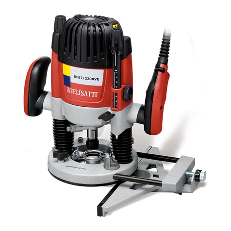
Felisatti RF67/2200 Assembly instructions

1
Operating/Safety Instructions
Consignes de fonctionnement/sécurité
Instrucciones de funcionamiento y seguridad
RF67/2200 Electric Router /
Fraiseuse électrique /
Fresadora eléctrica
Consumer Information
Renseignement des consommateurs
Información para el consumidor
WARNING: To reduce the risk of injury, the user must read and understand the
operating instructions before using this product.
AVERTISSEMENT: Pour réduire les risques de blessure, l’utilisateur doit lire et comprendre
les consignes d’utilisation avant d’utiliser ce produit.
ADVERTENCIA: para reducir el riesgo de lesiones, el usuario debe leer y entender las
instrucciones de operación antes de usar esta herramienta.
www.felisatti.es

2
TABLE OF CONTENTS
SAFETY.............................................................................................................................................5
General power tool safety warnings ..............................................................................................5
Additional safety rules for routers..................................................................................................7
Double insulation...........................................................................................................................7
DESCRIPTIONS & SPECIFICATIONS ..............................................................................................8
Functional description...................................................................................................................8
Symbols........................................................................................................................................9
Specifications................................................................................................................................9
ASSEMBLY & OPERATION............................................................................................................10
Adjusting depth of cut.................................................................................................................. 13
Mounting template guides........................................................................................................... 16
OPERATING INSTRUCTIONS.........................................................................................................16
Powering the Tool On and Off.....................................................................................................16
Variable Speed Control...............................................................................................................17
Cutting applications.....................................................................................................................18
MAINTENANCE & INSPECTION.....................................................................................................19
Service........................................................................................................................................19
Power Cord.................................................................................................................................19
Tool Lubrication ..........................................................................................................................19
Ventilation Openings................................................................................................................... 19
Bearings......................................................................................................................................19
Inspect Accessories....................................................................................................................19
Inspect Screws............................................................................................................................19
ACCESSORIES............................................................................................................................... 20
Standard Accessories.................................................................................................................20
SERVICE LOCATIONS.................................................................................................................... 20

3
TABLE DES MATIÈRES
SÉCURITÉ.......................................................................................................................................21
Règles générales de sécurité...................................................................................................... 21
Règles additionnelles de sécurité pour les fraiseuses .................................................................23
Double isolation ..........................................................................................................................23
DESCRIPTIONS & SPÉCIFICATIONS ............................................................................................ 24
Description fonctionnelle.............................................................................................................24
Symboles....................................................................................................................................25
Specifications.............................................................................................................................. 25
ASSEMBLAGE & UTILISATION ..................................................................................................... 26
Avant l'utilisation .........................................................................................................................26
Installation et désinstallation de la fraise (2 options)....................................................................26
Sélection et installation de l'outil à fraiser....................................................................................26
Réglage de la profondeur de coupe ............................................................................................29
Montage des guides pour gabarit................................................................................................32
INSTRUCTIONS D'UTILISATION....................................................................................................32
Mise en marche et arrêt de la machine........................................................................................32
Réglage de la vitesse de rotation................................................................................................33
Applications de coupe.................................................................................................................34
MAINTENANCE & INSPECTION.....................................................................................................35
Service........................................................................................................................................35
Cordon d’alimentation.................................................................................................................35
Lubrification de la machine..........................................................................................................35
Conduits d'aération.....................................................................................................................35
Roulements................................................................................................................................. 35
Inspection des accessoires ......................................................................................................... 35
Inspection des vis........................................................................................................................35
ACCESSOIRES............................................................................................................................... 36
Accessoires standard..................................................................................................................36
POINTS DE SERVICE ..................................................................................................................... 36

4
TABLA DE CONTENIDO
SEGURIDAD....................................................................................................................................37
Advertencias de seguridad generales para las herramientas eléctricas.......................................37
Normas de seguridad adicionales para fresadoras......................................................................39
Doble aislamiento........................................................................................................................39
DESCRIPCIONES Y ESPECIFICACIONES.....................................................................................40
Descripción funcional..................................................................................................................40
Símbolos.....................................................................................................................................41
Especificaciones.........................................................................................................................41
MONTAJE Y FUNCIONAMIENTO...................................................................................................42
Antes de utilizar la herramienta...................................................................................................42
Instalar y retirar la broca (2 opciones)......................................................................................... 42
Ajustar la profundidad del corte...................................................................................................45
Plantillas guía de montaje...........................................................................................................48
INSTRUCCIONES DE FUNCIONAMIENTO..................................................................................... 48
Activar y desactivar la herramienta..............................................................................................48
Control de velocidad variable......................................................................................................49
Aplicaciones de corte..................................................................................................................50
MANTENIMIENTO E INSPECCIÓN................................................................................................. 51
Servicio.......................................................................................................................................51
Cable de alimentación.................................................................................................................51
Lubricación de la herramienta.....................................................................................................51
Aberturas de ventilación..............................................................................................................51
Rodamientos............................................................................................................................... 51
Inspeccione los accesorios .........................................................................................................51
Inspeccione los tornillos..............................................................................................................51
ACCESORIOS.................................................................................................................................52
Accesorios de serie.....................................................................................................................52
CENTROS DE SERVICIO................................................................................................................ 52

5
SAFETY
GENERAL POWER TOOL SAFETY WARNINGS
WARNING Read all safety warnings and all instructions. Failure to follow the warnings and
instructions may result in electric shock, fire and/or serious injury.
Save all warnings and instructions for future reference.
The term “power tool” in the warnings refers to your mains-operated (corded) power tool or battery-
operated (cordless) power tool.
1) Work area safety
a) Keep work area clean and well lit. Cluttered or dark areas invite accidents.
b) Do not operate power tools in explosive atmospheres, such as in the presence of
flammable liquids, gases or dust. Power tools create sparks which may ignite the dust or
fumes.
c) Keep children and bystanders away while operating a power tool. Distractions can cause
you to lose control.
2) Electrical safety
a) Power tool plugs must match the outlet. Never modify the plug in any way. Do not use
any adapter plugs with earthed (grounded) power tools. Unmodified plugs and matching
outlets will reduce risk of electric shock.
b) Avoid body contact with earthed or grounded surfaces, such as pipes, radiators,
ranges and refrigerators. There is an increased risk of electric shock if your body is earthed
or grounded.
c) Do not expose power tools to rain or wet conditions. Water entering a power tool will
increase the risk of electric shock.
d) Do not abuse the cord. Never use the cord for carrying, pulling or unplugging the
power tool. Keep cord away from heat, oil, sharp edges or moving parts. Damaged or
entangled cords increase the risk of electric shock.
e) When operating a power tool outdoors, use an extension cord suitable for outdoor use.
Use of a cord suitable for outdoor use reduces the risk of electric shock.
f) If operating a power tool in a damp location is unavoidable, use a ground fault circuit
interrupter (GFCI) protected supply. Use of an GFCI reduces the risk of electric shock.
3) Personal safety
a) Stay alert, watch what you are doing and use common sense when operating a power
tool. Do not use a power tool while you are tired or
under the influence of drugs,
alcohol
or medication. A moment of inattention while operating power tools may result in
serious personal injury.
b) Use personal protective equipment. Always wear eye protection. Protective equipment
such as dust mask, non-skid safety shoes, hard hat, or hearing protection used for
appropriate conditions will reduce personal injuries.
c) Prevent unintentional starting. Ensure the switch is in the off-position before
connecting to power source and/or battery pack, picking up or carrying the tool.
Carrying power tools with your finger on the switch or energising power tools that have the
switch on invites accidents.
d) Remove any adjusting key or wrench before turning the power tool on. A wrench or a
key left attached to a rotating part of the power tool may result in personal injury.
6
e) Do not overreach. Keep proper footing and balance at all times. This enables better
control of the power tool in unexpected situations.
f) Dress properly. Do not wear loose clothing or jewellery. Keep your hair, clothing and
gloves away from moving parts. Loose clothes, jewellery or long hair can be caught in
moving parts.
g) If devices are provided for the connection of dust extraction and collection facilities,
ensure these are connected and properly used. Use of dust collection can reduce dust-
related hazards.
4) Power tool use and care
a) Do not force the power tool. Use the correct power tool for your application. The correct
power tool will do the job better and safer at the rate for which it was designed.
b) Do not use the power tool if the switch does not turn it on and off. Any power tool that
cannot be controlled with the switch is dangerous and must be repaired.
c) Disconnect the plug from the power source and/or the battery pack from the power
tool before making any adjustments, changing accessories, or storing power tools.
Such preventive safety measures reduce the risk of starting the power tool accidentally.
d) Store idle power tools out of the reach of children and do not allow persons unfamiliar
with the power tool or these instructions to operate the power tool. Power tools are
dangerous in the hands of untrained users.
e) Maintain power tools. Check for misalignment or binding of moving parts, breakage of
parts and any other condition that may affect the power tool’s operation. If damaged,
have the power tool repaired before use. Many accidents are caused by poorly maintained
power tools.
f) Keep cutting tools sharp and clean. Properly maintained cutting tools with sharp cutting
edges are less likely to bind and are easier to control.
g) Use the power tool, accessories and tool bits etc., in accordance with these
instructions, taking into account the working conditions and the work to be performed.
Use of the power tool for operations different from intended could result in a hazardous
situation.
5) Service
a) Have your power tool serviced by a qualified repair person using only identical
replacement parts. This will ensure that the safety of the power tool is maintained.

7
ADDITIONAL SAFETY RULES FOR ROUTERS
Hold power tool by insulated gripping surfaces, because the cutter may contact its
own cord. Cutting a “live” wire may make exposed metal parts of the power tool “live” and
shock the operator.
Use clamps or another practical way to secure and support the workpiece to a stable
platform. Holding the work by your hand or against the body leaves it unstable and may
lead to loss of control.
DOUBLE INSULATION
To ensure safer operation of this tool, Felisatti has adopted a double insulation design. “Double
Insulation” means that two physically separated insulation systems have been used to insulate the
electrically conductive materials connected to the power supply from the outer frame handled by
the operator.
To keep the double insulation system effective, follow these precautions:
• Be careful not to pierce the motor housing as this could damage the efficiency of the double
insulation system.
• Only Felisatti Authorized Service Centers should disassemble or assemble this power tool, and
only genuine Felisatti replacement parts should be installed.

8
DESCRIPTIONS & SPECIFICATIONS
WARNING: Disconnect the plug from the power source before making any assembly,
adjustments or changing accessories. Such preventive safety measures
reduce the risk of starting the tool accidentally.
FUNCTIONAL DESCRIPTION
A- Depth Adjustment Knob
B- Variable Speed Control
C- Micro Adjustment Knob
D- Turret Stop Rod
E- Side Handles
F- Coarse Adjustment Knob
G- Arrow Indicator
H- Turret Stop Rod Locking
Screw
I- Depth Stop Turret
J – Spindle
K – Spindle Lock (Shaft Lock)

9
SYMBOLS
Some of the following symbols may be used on your tool. Please study them and learn their
meaning. Proper interpretation of these symbols will allow you to operate the tool better and safer.
Symbol Name Designation/Explanation
V Volts Voltage (potential)
A Amperes Current
Hz Hertz Frequency (cycles per second)
W Watt Power
(n0) No load speed Rotational speed, at no load
.../min Revolutions or reciprocation per minute Revolutions, strokes, surface speed,
orbits, etc. per minute
Class II construction Designates double insulated construction
tools
Alternating current Type or a characteristic of current
Safety Alert Precautions that involve your safety
SPECIFICATIONS
Power Source Single-Phase, 120V ~ 60Hz
Amps 15
No-Load Speed 12000-21000 RPM
Collet 1/4 Inch & 1/2 inch (8mm &12mm)
Max Bit Diameter* 3-1/2 inch (88.9 mm)
Weight 13.1 lbs
*Router bits over 1-1/2” diameter should be used only with the router mounted in a router table. The router base
plate must be removed to to accept bits larger 21/2” diameter. Consult the router table’s user manual for maximum
bit diameter that can be used in the router table
Indicates that the product was tested and has met the certification requirements for
electrical products.

10
ASSEMBLY & OPERATION
PRIOR TO OPERATION
1. Check Power Supply
Ensure that the power source to be utilized conforms to the power source requirements
specified on the tool nameplate. Ensure the receptacle being used accepts the plug tightly. If
a faulty receptacle is used, it may cause overheating, resulting in a serious hazard.
2. Check Work Area
Confirm that the work site is placed under appropriate conditions conforming to precautions
prescribed in the safety section of this manual.
3. Before Plugging in the Tool
Ensure that the power tool switch is in the OFF position to prevent the tool from accidental
start up, which could cause serious injury.
INSTALLING AND REMOVING THE ROUTER BIT ( 2 options)
WARNING: Disconnect tool from power source. Make sure the correct collet is selected to
match the bit shank diameter and that the collet is securely “snapped” into the collet nut before
proceeding.
MILLING HEAD SELECTION AND INSTALLATION
(Option 1)
a) Insert the Depth Adjustment Wrench (M) into the Height Adjustment Access (L) and turn
counter clockwise until the collet and collet nut (N) extend fully through the base.– Fig 1
(It may be necessary to rotate the Depth Stop Turret to the flat surface without any stops
(see area marked with “X”- Fig. 11) to allow the collet to fully extend through the base.)
b) Insert the Depth Adjustment Wrench (M) into the Above Table Spindle Lock Access ® and
rotate clockwise until it stops turning. Rotate Spindle (J) until the Spindle Lock (K) pin
engages. When the Spindle Lock pin is correctly engaged, you will not be able to rotate the
spindle. – Fig 2
c) Using the included 22mm Collet Nut Wrench (Q), turn the collet nut counter clockwise to
loosen the collet. If a bit is already in the collet the collet nut will loosen for approximately 1
turn and then become tight again. Continue turning the nut counter clockwise with the
wrench until the nut is loose again. At this point the bit should be released and easy to
remove from the collet– Fig 3
d) Insert the router bit and rotate the collet nut with the 22mm wrench clockwise to tighten the
collet. Always be sure that at least 80% of the router bit shank is inserted in the collet but
never allow the bit shank to “bottom out” in the collet. – Fig 4
e) Insert the Depth Adjustment Wrench (M) into the Above Table Spindle Lock Access ® and
rotate counter clockwise until it stops turning. – Fig 5a
f) Turn the height adjustment knob clockwise until the router bit returns fully inside the base. –
Fig 5b
g) Before operating the router, follow directions in the section in this manual titled “Adjusting
Depth of Cut” to properly set the depth of cut.
h) To remove a router bit from the collet, follow steps a, b, and c and then remove the router bit.
WARNING: Failure to disengage the spindle lock or remove the wrench before operating this
power tool could result in injury or damage to the tool.

11

12
(Option 2)
a) Release the plunge lock lever (P) and turn
the depth adjustment knob (A) counter
clockwise to raise the router motor to its
highest position. – Fig. 6
b) Next, position the router on its side or
stand it upside down on its cap before
continuing.
c) While pressing the spindle lock button (K),
rotate the spindle (J) until the spindle lock
pin engages the spindle. When the spindle
lock pin engages, you will not be able to
turn the spindle.
d) While pressing the spindle lock button,
use the 22 mm wrench to rotate the collet
(N) counter clockwise to loosen the collet.
If a bit is already in the collet the collet nut
will loosen for approximately 1 turn and
then become tight again. Continue turning
the nut counter clockwise with the wrench
until the nut is loose again. At this point
the bit should be released and easy to
remove from the collet – Fig. 7
e) Insert the router bit inside the collet
making sure that at least 80% of the
router bit shank is inside the collet but
never allow the bit shank to “bottom out”
in the collet.
f) While pressing the spindle lock button (H),
rotate the spindle (J) until the spindle lock
pin engages the spindle. Using the 22 mm
wrench, turn the collet clockwise until the
collet is tight. – Fig. 8
g) Before operating the router, follow the
directions in the section of this manual
titled "Adjusting Depth of Cut" to properly
set your depth of cut.
h) To remove a router bit, follow steps a, b,
c, and d and then remove the router bit.
WARNING: Failure to disengage the spindle
lock or remove the wrench before operating this
power tool could result in injury or damage to the
tool.
Fig. 6
Fig. 7
Fig.8

13
ADJUSTING DEPTH OF CUT
WARNING! Disconnect tool from power source
There are two methods for adjusting the depth of
cut on the RF67/2200 Router. The Depth
Adjustment Knob (A) is best for non plunging
operations. The Depth Stop Turret (I) and Turret
Stop Rod (D) is best for operations where there
are repeatable depth settings or two or more
depth settings may be needed.
1) Depth Adjustment Knob: –Fig 9.
When Plunge Locking Lever (P) is released,
the Depth Adjustment Knob (A) may be used
to raise and lower the router motor. Turn the
knob clockwise to increase the depth of cut
and counter-clockwise to reduce the depth
of cut. Once the desired depth of cut is
reached, push up on the Plunge Locking
Lever (P) to lock the setting. Always
be sure that the Plunge Locking Lever (P)
has been released and the Turret Stop Rod
(D) cannot hit a stop on the Turret (I) before
using the Depth Adjustment Knob (A). If
router is mounted in a router table, insert the
Depth Adjustment Wrench (M) into the Above
Table Height Adjustment Access (L) to raise
and lower the router motor. Turn the wrench
counter-clockwise to increase the depth of
cut and clockwise to reduce the depth of
cut.
Note: The Depth Adjustment Wrench (M) can
be inserted into the Depth Adjustment Knob
(A) and used to adjust the depth of cut.
2) Depth Stop Turret and Turret Stop Rod:
–Fig 10. The Depth Stop Turret (I) and Turret
Stop Rod (D) allow you to preset up to three
cut depths. For maximum plunge action, the
Depth Adjustment Knob (A) must be turned
counter-clockwise until the motor is at the
top of the rods. For fine adjustment of the
cutting depth, there are three stops attached
to the Depth Stop Turret (I) on the Base of
the RF67/2200. The Depth Stop Turret turns
so that each of the three stops can be
positioned under the Turret Stop Rod (D).
The Turret Stop Rod (D) has a Course
Adjustment Knob (F) that raises or lowers
the Turret Stop Rod to make large
Fig. 9
Fig. 10

14
adjustments quickly. The icro Adjustment
knob (C) allows for fine adjustment of the
Turret Stop Rod. You can set three different
depths of cut for the same bit using the
Turret and stops –Fig 11. Adjust the height of
the three stop screws as necessary so that
the difference in height is equal to the amount
of material to be removed with each cut.
3) Setting the Router to Zero Plunge Depth:
Rotate the turret (I) so that stop 3 is directly
under the Turret stop Rod – Fig 12. Loosen
turret stop rod locking screw (H) and raise
turret stop rod (D) to its highest position
using the course Adjustment Knob (F) – Fig
13. Release plunge locking lever (P) and
gently plunge the router motor until the router
bit barely touches the work surface. Lock the
plunge locking lever – Fig 14. Rotate the
coarse adjustment knob (F) to move the turret
rod downward until it contacts stop 3. Raise
the Turret Stop Rod until the arrow indicator
is aligned with the closest large increment on
the scale (i.e.,
1
⁄
4
",
1
⁄
2
",
3
⁄
4
", 1", etc.) – Fig 15.
Turn the micro adjustment knob (C) until the
turret stop rod contacts the stop screw.
Tighten the stop rod locking screw – Fig 16.
Your router is now set to zero plunge depth.
Release the plunge locking level to allow the
router’s motor to return to its maximum
height. To adjust the router to your required
cutting depth, rotate the coarse Adjustment
screw to raise the Turret Stop Rod until the
measurement on the scale is equal to the
amount required for your final depth of cut.
Fig. 11
Fig. 12
Fig. 13

15

16
MOUNTING TEMPLATE GUIDES
WARNING! Disconnect tool from power source.
For template routing the Felisatti RF67/2200 accepts
standard template guides which are available
separately. To use template guides an optional
adapter ring must be attached to the base plate
using the two slotted screws provided. Remove the
slotted screws from the base plate, insert the
adapter ring with the flat side toward the router body.
Install and tighten the screws to secure the adapter
ring. - Fig. 17
The base plate has been centered at the
factory, however, if the base plate has been
removed and remounted some adjustment may
be necessary to center the template guides to
the router bit. To adjust, loosen the four base
plate screws that secure the base plate to the
router, reposition the base plate and tighten the
screws.
Fig. 17
OPERATING INSTRUCTIONS
WARNING! Make sure that the voltage from
the power supply matches the voltage specified
on the tool. Before plugging in the tool ensure
that the bit is properly inserted and tightened
and that it spins freely.
1. Powering the Tool On and Off
a) Plug in the tool with the Trigger Switch in the OFF
position and the lock button released.
b) Hold the router firmly by both handles with the bit
away from you and positioned so that the bit is
not in contact with the wood or any part of your
body or clothing.
c) Start the tool by depressing the Trigger Switch.
Fig 18
d) Lock the tool in the run position by depressing
the Locking Button with your thumb while the
Trigger Switch is on. Release the Locking Button
by momentarily depressing the Trigger Switch
and releasing.
e) Turn off the tool by releasing the Trigger Switch.
Fig. 18

17
2. Variable Speed Control
WARNING: Always unplug the router before
making any speed adjustment.
The Felisatti RF67/2200 is equipped with an
electronic variable speed control feature.
ElectronicVariable Speed Control
This speed control has an infinite number of
speeds from 12000 to 21000 RPM. The speed
is adjusted by turning the speed control knob
(B)- Fig 19. Consult the router bit manufacturer
for recommended bit speed.
Constant Speed
The electronic speed control keeps constant
speed at all levels. If the motor speed decreases
in use you may be exceeding the load capacity
of the tool. This could cause damage to the
motor by overheating. Reducing the depth of cut
so that more passes are required and/or slowing
the rate of feed will reduce the power
requirements on the router.
Soft Start Feature
Electronic feedback control minimizes torque
twist customary in larger routers by limiting the
speed at which motor starts.
Overload Protection
Automatic disconnect in order to keep save the
machine when an overload is produced
Fig. 19
RF67/2200 Router Speed Dial Settings
RPM
Dial Settings
Recommended Maximum Speeds for Felisatti router bits
Bit Diameter Max RPM
1" 24000
1-1/4" 18000
2-1/4" 16000
3-1/2" 12000

18
CUTTING APPLICATIONS
WARNING! Always clamp your work piece
securely before making any cuts.
1) Edge Cutting - Fig. 20 & Fig. 21
Consider the material that you are cutting and
the amount of material that will be removed
before using the tool. Make sample cuts on
scrap wood before cutting the actual work
piece. The router bit rotates in a clockwise
direction when viewed from the top of the
router. On external edge treatments move the
router counter clockwise from left to right. For
internal cutting move the router clockwise
from right to left.
WARNING! Avoid climb cutting (moving the
router clockwise with the rotation of the bit).
Climb cutting increases the potential of losing
control of the router and the risk of possible
injury. - Fig. 22
2) Plunge Cutting-Fig. 9 & Fig. 10
To make a plunge cut, grasp the router by
both handles (E), position the router over the
area to be routed, turn the power on, release
the Plunge Locking Lever (P) and push down
on the Router Handles (E). When the Turret
Stop Rod (D) contacts stop 1 on the Depth
Stop Turret (I), tighten the Plunge Locking
Lever (P), and begin routing. Always allow
the router to reach full speed before you
begin the plunge. After the first cut is
complete, release the Plunge Locking Lever
(P), allow the Router Motor to return to the
top of the rods, TURN THE POWER OFF
AND WAIT FOR THE BIT TO COME TO A
COMPLETE STOP, and move the Turret to
stop 2, Repeat the plunge operation as you
did for the first cut. The third cut is
completed using the same steps with stop 3.
Table Mouting
The Felisatti RF67/2200 can also be mounted to
a router table. To mount the router, please follow
the instruction included with the router table.
The RF67/2200 includes a pattern for drilling the
mounting screw holes and for drilling the Above
Table Height Adjustment Access hole.
Fig.20
Fig. 21

19
MAINTENANCE & INSPECTION
MAINTENANCE
Service
It is recommended that all service on your Felisatti tool be performed by an
Authorized Felisatti service center. Service by unauthorized service personnel
may result in misplaced internal components resulting in risk of tool
malfunction and personal injury to the tool user.
Power Cord
Check that the power cord is in good condition. If it is not, have it replaced
immediately at a Felisatti Authorized service center.
Tool Lubrication
All power tools require care and attention. Every couple of years, we
recommend leaving the tool with an authorized Felisatti service center for a
general cleaning and lubrication.
Ventilation Openings
Make sure the air vents are always kept clean and free of obstacles. If
clogged, vacuum out obstruction. It is recommended that you blow off the
entire tool with compressed air after each use.
Bearings
We recommend that at every couple of years, or when needed, the bearings
be inspected by an authorized Felisatti service technician. Bearings that
become very noisy should be replaced at once to avoid overheating or motor
failure.
Inspect Accessories
Regularly inspect your router bits. Using worn accessories with diminish the
efficiency of the work and could damage the tool's motor.
Inspect Screws
Regularly inspect all screws in your power tool and make sure they are
properly tightened. Loose screws should be retightened immediately.

20
ACCESSORIES
ACCESSORIES
Standard Accessories
• 22 mm Collet Nut Wrench
• Depth Adjustment Wrench
• 1/4" and 1/2" Collets
• Vacuum Adapter
SERVICE LOCATIONS
SERVICE
To locate a Felisatti Authorized Service Center near you, visit our web site at: www.felisatti.es
Table of contents
Languages:
Other Felisatti Power Tools manuals

Felisatti
Felisatti SD230/2200 User manual

Felisatti
Felisatti RF100/710 User manual

Felisatti
Felisatti RF55/1000E User manual

Felisatti
Felisatti RF30/430 User manual

Felisatti
Felisatti JS85/701 User manual

Felisatti
Felisatti RF62/1500VE User manual

Felisatti
Felisatti RF67/2200VE User manual

Felisatti
Felisatti HF25/1500 User manual

Felisatti
Felisatti RSF120/1010E User manual

Felisatti
Felisatti HF12,5/1050 User manual