LEGRAND WattStopper BZ-150 User manual

Installation Instructions
BZ-150
Power Pack
SPECIFICATIONS
Voltages........................................... 120/230/277VAC. 50/60Hz
Load Requirements
Ballast............................................... 20amp @120/277VAC
Incandescent............................................ 20amp @120VAC
Motor...................................................... 1HP @120/240VAC
Output .......................225mA @24VDC (with relay connected)
Low Voltage Input
Control ON ......................................................... 12-24VDC
Hold ON .............................................................. 12-24VDC
Hold OFF ............................................................ 12-24VDC
Manual ON (momentary switch required) .......... 12-24VDC
Operating Temperature..............................32°-104°F (0-40°C)
Santa Clara, CA 95050

Call 800.879.8585 for Technical Support
DESCRIPTION
The BZ-150 power pack is the foundation for any low voltage lighting control
system. The BZ-150 supplies low voltage power to occupancy sensors and other
control devices, switching line voltage in response to signals from control devices.
The BZ-150 power pack is attached to existing junction boxes or mounted into
fixture wiring trays.
Low voltage wiring should use at least 22-gauge wire. High voltage connections
should use at least 14-gauge. Always check local building codes. After initial
wiring is complete, check wiring diagrams to verify the power pack is wired
correctly. Improper wiring can cause damage to the power pack, lighting system,
occupancy sensor and other control devices.
INSTALLATION
WARNING
TURN POWER OFF AT CIRCUIT
BREAKER BEFORE INSTALLING
POWER PACKS.
WIRING
Low
Voltage
High
Voltage
+24VDC
Common
Red
White
Neut. Power Pack
Blue
Black
Red
Dry
Contact
Lighting
Load
277VAC
Black
120VAC
+12-24VDC In
Hold OFF
+12-24VDC In
Hold ON
Any 3-Wire
24VDC
Sensor
Hot Red
Brown
Orange
Grey
Control
Momentary Switch (optional)
Low Voltage Wires
1. Make sure power has been turned off
at the circuit breaker.
2. Connect wires as shown in the wiring
diagram below, or as shown in the
BI-LEVEL CONTROL section.

Installation Notes
1. Power packs should be installed in
accordance with state, local and national
electrical codes and requirements.
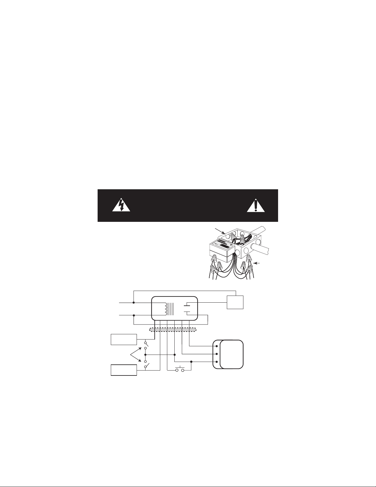
2. Power packs are designed to attach to
existing or new electrical enclosures with 1/2
inch knockouts.
3. Most applications require UL listed, 18-22
AWG, 3-conductor, Class 2 cable for low voltage wiring. For plenum return
ceilings, use UL listed plenum-approved cables.
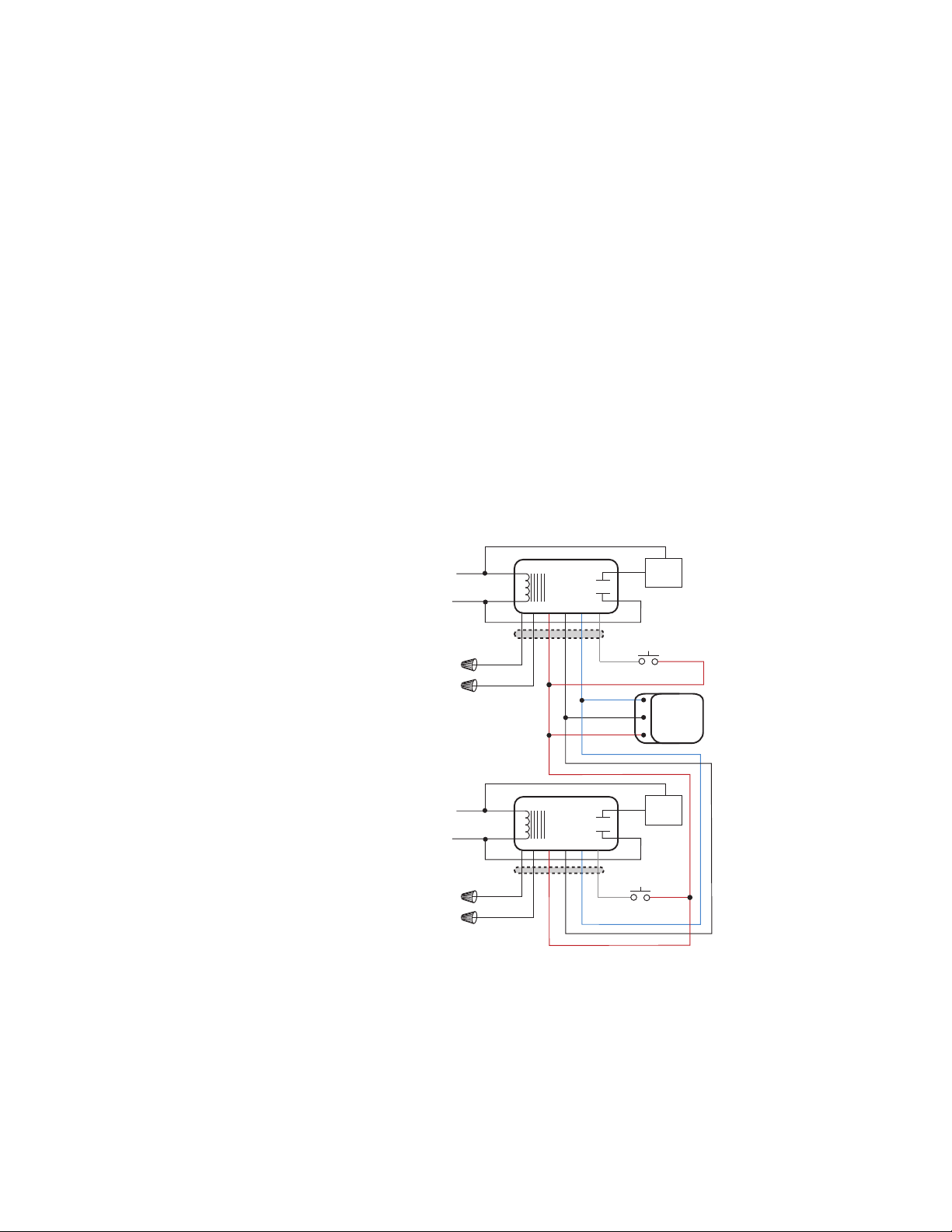
4. The BZ-150 is a Class 2 Output Power Supply, suitable for parallel
interconnection of up to 10 units maximum. This power pack is UL Listed for
Interconnection of Power Sources in accordance with National Electric Code.
OPERATION
With the BZ-150, the load can be turned ON and OFF automatically using an
occupancy sensor input, a timer, panel or BAS input, and manually from an
optional low voltage momentary switch. Use the Mode Switch to select either the
Auto ON mode, or the Manual ON mode. Remove power from the BZ-150 when
changing the switch setting, or cycle power to it after changing the setting.
Auto ON (Mode Switch LEFT - default)
The occupancy sensor input, Hold ON input and the optional momentary switch
input can all be used turn ON the load.
When the load is turned OFF using the momentary switch, the BZ-150 does not
turn it ON automatically until after the sensor time delay expires (e.g., as might
be required for a presentation). Pressing the momentary switch before the sensor
time delay expires turns ON the load.
When the occupancy sensor’s time delay expires, the BZ-150 reverts to Auto ON
mode and it turns ON the load with the next input from the occupancy sensor.
Manual ON (Mode Switch RIGHT)
Occupants must press the low voltage momentary switch to turn ON the load.
When the occupancy sensor is the only input keeping the load ON, the load turns
OFF when the sensor’s time delay expires. If the sensor input re-triggers within
30 seconds after the load turns OFF, the load turns ON again. After 30 seconds
expire with no sensor input, press the momentary switch to turn ON the load.
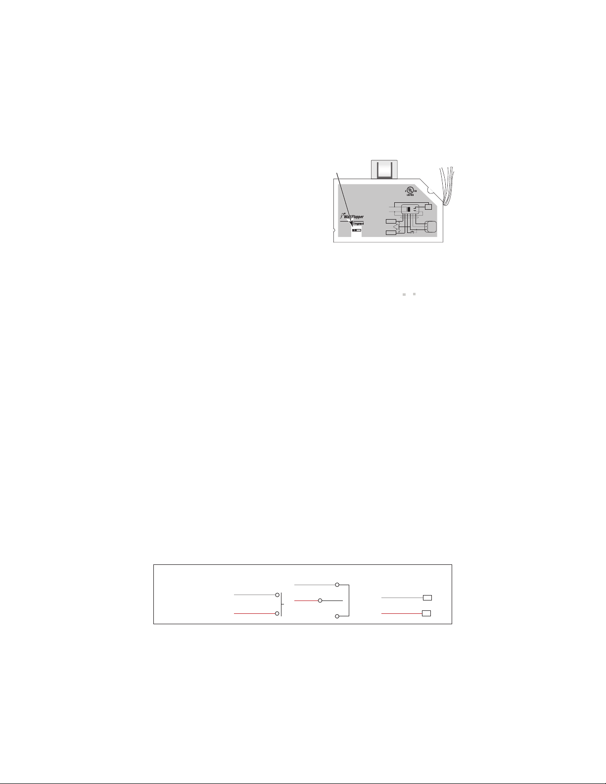
Mode
Switch
UL 2043 Plenum Rated
Santa Clara, CA
800.879.8585
APPLIANCE
CONTROL
88T9
Auto
ON
Manual
ON
120/230/277VAC, 50/60Hz, 225mA output
20A ballast or incandescent load
Motor load: 1HP@120/240VAC
Class 2 power supply
Model #:
BZ-150 Power Pack
08405r1
Low Voltage
Inputs
+24VDC
Common
Red
White
Neut. Power Pack
Blue
Black
Red
Dry
Contact
Lighting
Load
277VAC
Black
120VAC
+12-24VDC In
Hold OFF
+12-24VDC In
Hold ON
Any 3-Wire
24VDC
Sensor
Hot Red
Brown
Orange
Grey
Control
Momentary Switch (optional)
Low Voltage Wires
2-wire Push Button
Red
24VDC
Grey
Manual ON
3-wire Momentary, LVS-1
Red
24VDC
Grey
Manual ON
Install
Jumper
Wire
Multi-button Switch, L(x)S
Do not use pilot or locator
light connections
Red
24VDC
Grey
Manual ON S(x)
Com
Low Voltage
Momentary
Switch Option
Wiring

LOW VOLTAGE INPUTS
Four +12-24VDC input wires are provided to control the load relay. The inputs may
be used in combination or individually, depending on the needs of the application.
See the WIRING section for wiring information.
Maintained Inputs:
Control ON (Blue) – This input is intended for occupancy sensor input.
Applying 12-24VDC closes the relay.
Remove the voltage and the relay opens if no other input is holding it closed.
Hold ON (Orange) – This input is intended for timer or panel input.
Applying 12-24VDC closes the relay.
Remove the voltage and the relay opens if no other input is holding it closed.
It overrides Control ON input.
Hold OFF (Brown) – This input is used for timer, panel, BAS or load shed input.
Applying 12-24VDC opens the relay.
Remove the voltage and the relay can accept any other input.
It overrides Control ON and Hold ON inputs.
Momentary Input:
Manual ON/OFF (Grey) – This
input is for a low voltage
momentary switch. Applying
12-24VDC momentary input
changes the relay to the
opposite state.
It overrides Control ON, Hold
ON and Hold OFF inputs.
BILEVEL CONTROL
WITH MANUAL ON
The diagram to the right shows
how to configure BZ-150s to
provide bi-level lighting control
with both Automatic ON and
Manual ON features.
As shown, upon occupancy
detection load A turns ON
automatically. To turn ON load B
the user must press momentary
switch B. Both loads turn OFF
automatically when the sensor
time delay expires, or manually
using switch A and B.
+24VDC
Common
Red
White
Neut. BZ-150
(A)
AUTO ON
Blue
Black
Red
Lighting
Load (A)
277VAC
Black
120VAC
Any 3-Wire
24VDC
Sensor
Hot Red
Brown
Orange
Control
Low Voltage Wires
Red
White
Neut. BZ-150
(B)
MANUAL ON
Blue
Black
Red
Lighting
Load (B)
277VAC
Black
120VAC
Hot Red
Brown
Orange
Grey
Momentary Switch (B)
Low Voltage Wires
Grey
Momentary Switch (A)
Parallel interconnect for bi-level load control
from a single sensor with manual ON

Over Current Protection:
The BZ-150 contains built-in short circuit and thermal protection circuitry that
shuts down the +24VDC output (low voltage red wire) to prevent permanent
damage to the power pack. Removing the excess load from the output restores
the BZ-150 to proper operation. Connect the excess load to another power pack.
LED Indicator
The LED on the reverse side of the BZ-150 indicates the following conditions:
• LED OFF: no power to the BZ-150, or the +24VDC output is shorted.
• LED blinking continuously: current output limit is exceeded (too many
sensors are connected to the power pack); +24VDC output shut down.
• LED ON, blinks once every 4 or 5 seconds: the relay is closed (load ON).
• LED ON continuously: the relay is open (load OFF).
TROUBLESHOOTING
The lights came ON automatically after I deliberately turned them
OFF for a presentation.
• The BZ-150 is set for the Auto ON Mode and the occupancy sensor time delay
expired. The BZ-150 reverted to Auto ON and then motion was detected.
-- Consider increasing occupancy sensor sensitivity and/or time delay.
-- Generate more motion during presentations.
The load does not turn ON with occupancy detection.
• Mode Switch is set to Manual ON.
• Hold OFF input is active.
The load does not turn OFF after sensor time delay expires.
• Hold ON input is active.
The load does not respond when I press the momentary switch.
• Check wiring.
The load does not come on automatically although the Mode Switch is
set to Auto ON.
• Cycle power to the unit to reset operating mode to Auto ON. Mode Switch
location was changed while the power pack was was powered (line voltage).
The load comes on automatically with occupancy although the Mode
Switch is set to Manual ON.
• Cycle power to the unit to reset operating mode to Manual ON. Mode Switch
location was changed while the power pack was was powered (line voltage).

WARRANTY INFORMATION
Watt Stopper/Legrand warranties its products to be free of defects in materials
and workmanship for a period of five (5) years. There are no obligations or
liabilities on the part of Watt Stopper/Legrand for consequential damages arising
out of, or in connection with, the use or performance of this product or other
indirect damages with respect to loss of property, revenue or profit, or cost of
removal, installation or reinstallation.
2800 De La Cruz Boulevard, Santa Clara, CA 95050
Technical Support: 800.879.8585
www.wattstopper.com
08616r3 6/2009
ORDERING INFORMATION
Load Range
Catalog
No.
Description Input
Voltage
Ballast
(A)
Incan.
(A)
Motor
(hp)
Output
BZ-50 Power Pack 120/230/
277VAC,
50/60Hz
20 20 1 24VDC,
225mA
w/relay
connected
BZ-150 Power Pack,
Hold ON/OFF,
Manual ON
120/230/
277VAC,
50/60Hz
20 20 1 24VDC,
225mA
w/relay
connected
Please
Recycle
Table of contents
Other LEGRAND Power Pack manuals