1-1Piper 100/200Description of the System
1Description of the System
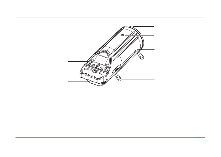
1.1 Features
Precision Engineered and designed to maintain its accuracy over time and temperature,
the Piper projects a beam up to 200 meters (650 feet).
Versatility Powered by a rechargeable Lithium-Ion battery, the Piper is the smallest,
professional pipe laser ever made. When sitting level the Piper can self-level
over its entire grade range, or can be placed inside the pipe for second day
setups. In the manhole, in the pipe, or over the top, the Piper can work for you.
Intelligence The cross-axis compensation function maintains the grade accuracy regardless
of the roll of the laser up to three degrees. The Alignmaster™ feature (Piper
200) seeks and locates the target automatically for easy second day setups.
Ruggedness Waterproof, shock and temperature tested, the Piper is built “construction
tough” with a metal housing and shock absorbing bumper around the front
window.
Models There are two models of the Piper pipe laser described in this manual:
• Piper 100 - Red beam pipe laser
• Piper 200 - Red beam pipe laser with the Alignmaster™ feature.