manuals.online logo
Brands
  1. Home
  2. •
  3. Brands
  4. •
  5. Leigh
  6. •
  7. Power Tools Accessories
  8. •
  9. Leigh VRS1200 User manual

Leigh VRS1200 User manual

IMPORTANT
Watch the Online
Instructional Video
in the Support Section
at www.leighjigs.com
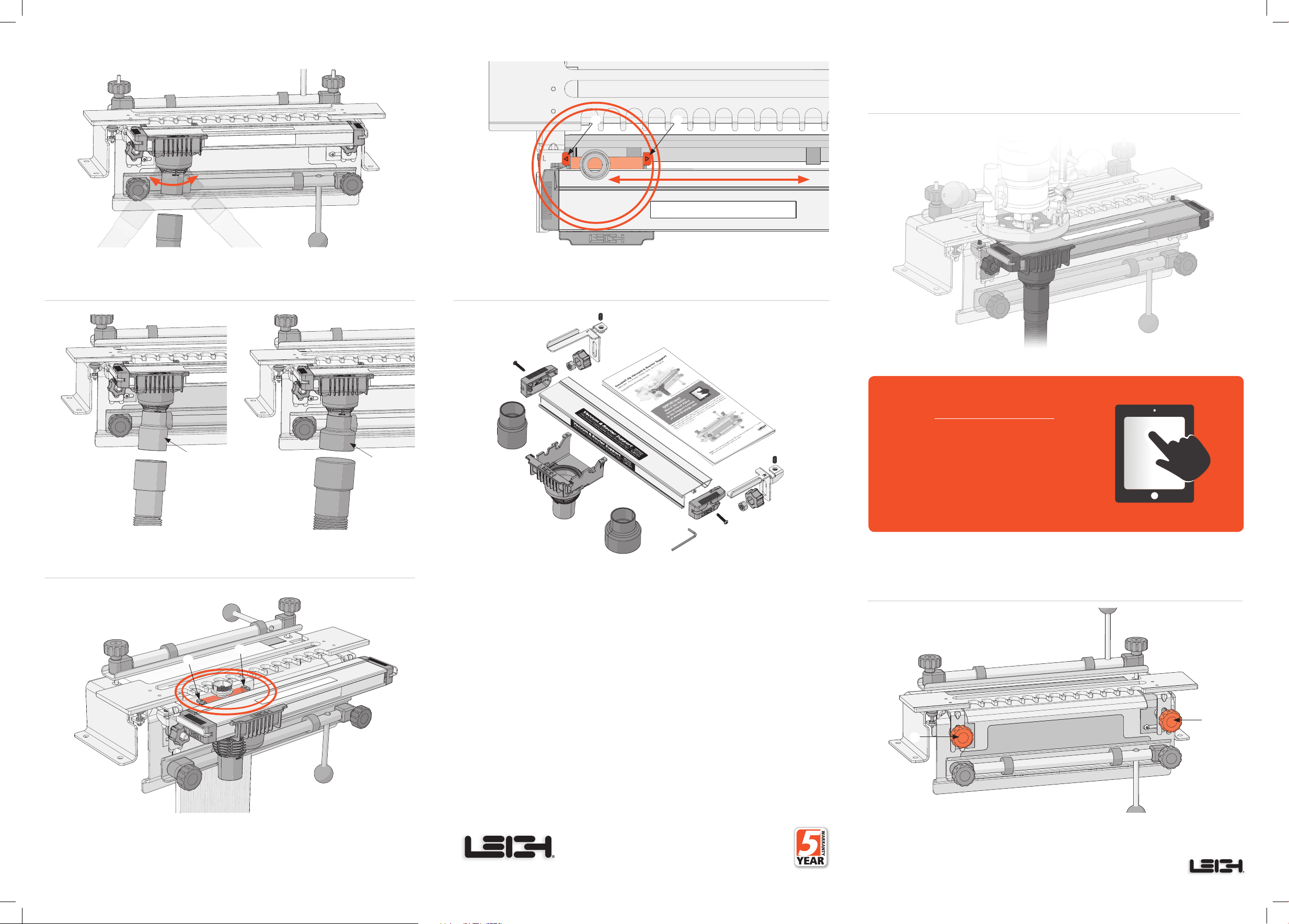
Step 13 Two hose adaptors, 2" (51mm) and 2 ½" (63.5mm), are included with the
VRS1200.
Step 14 When routing, the VRS1200 beam should be moved closer to the workpiece
for maximum chip collection. The tabs Aon either side of the vacuum box should be
close to, but not touching the workpiece. The guide bushing mounted to the router
base is positioned between the tabs of the dust collector.
Step 15 As the router moves across the beam, in and around the fingers, the guide bushing
attached to the router base contacts the vacuum box tabs
A
and moves it across the beam.
The vacuum box is always positioned for maximum dust collection.
Step 12 The swivel action vacuum port accepts a 1½"(38mm) diameter hose.Attach
your shop vacuum hose to the dust collection port on the vacuum box assembly.
Leigh Router Joinery Jigs
2" (51mm)
Adaptor 2-1/2" (63.5mm)
Adaptor
Step 2 To do the one-time setup, start by loosening the jigs template knobs Aand
raise the template about 1". Loosely tighten the knobs to hold the template in place.
A
A
Step 1 Watching the online video in addition to reading this user guide will reduce
your learning time dramatically. The video can be streamed to your smart phone or
tablet and used in your shop as a visual reference. Visit leighjigs.com and find the video
in the Support section.
A
A
Customer Support
1-800-663-8932 [email protected]
See Online Installation & Setup Video at www.leighjigs.com
Leigh Router Joinery Jigs
Printed in China
© 2018 Leigh Industries Ltd. All rights reserved.No part of this publication may be reproduced,
stored in a retrieval system,or transmitted in any form or by any means,electronic, mechanical,
recording, or otherwise, without the prior written permission of Leigh Industries Ltd.
Leigh Industries Ltd. is not an authorized dealer, distributor or service provider or otherwise
affiliated or associated with Porter Cable. 10/2018
Dovetail Jig Vacuum & Router Support
VRS1200 Fits Porter Cable 4210, 4212 & 4216
Installation & Setup Guide
For a list of Leigh dealers, visit www.leighjigs.com
US Patent No.7,507,060 B2 UK Patent No.GB2446909 Canada Patent No. 2,611,233
A A
PART DESCRIPTION PART NO. QUANTITY
A VRS1200 Beam Extrusion with Decals 426105 1
BLeft Support Bracket 426175 1
CRight Support Bracket 426180 1
D Support Bracket Set Screw 1/4"- 20 x 1/2” 426185 2
E Left End Cap with Spring 426220 1
F Right End Cap with Spring 426225 1
G End Housing Screw No.8 - 32 x 1" 426190 2
H Support Bracket Knob 426207 2
I Support Bracket Nut 3/8"-16 426208 2
J Vacuum Box Assembly 426230 1
K 2" (51mm) Vacuum Box Hose Adaptor 426150 1
L 2-1/2" (63.5mm) Vacuum Box Hose Adaptor 426155 1
M Hex Key 426216 1
NFully Illustrated Setup guide 426240 1
A
B
C
D
E
F
MG
H
I
J
K
L
D
GH
I
N
Step 7 Under light pressure, slide the VRS1200 beam onto the support brackets until
the end cap of the beam Ais even with the vertical portion of the bracket B. The beam is
held securely on the support brackets with an internal tension spring. This beam position
is used for the rest of the setup.
Step 10
If the VRS1200 beam is lower than the template, the straight edge will not
sit flat, as shown in the top drawing (exaggerated for clarity), and the beam must be
raised Ausing the set screw Bon each VRS1200 support bracket. If the VRS1200
beam is higher than the template, as shown in the bottom drawing, the beam must
be lowered Ausing the set screw Bon each VRS1200 support bracket. See next step
for adjustment procedure.
Step 11 To adjust the set screws, first remove the beam from the support brackets.
Loosen the left knob slightly and turn the support bracket Aoutwards. Using the
provided hex key B, turn the set screw
clockwise to raise
the beam, and
counter
clockwise to lower
the beam, as required. Next, adjust the right support bracket.
Place the beam back on the support brackets and check the height with the straight
edge (see Step 9). If necessary, repeat this one-time process until the template and the
ridge on the beam are at the same height.
Step 6 Raise the support bracket until the height adjusting screw A
touches the bottom
of the template bracket. Tighten the template knob
B.
Repeat Steps 5 and 6 at the right
end of the jig.
Step 5 Hold the VRS1200 left bracket Aoutwards at about a 45ºangle and slide
it over the template bolt Buntil it contacts the template bracket C. Turn the left
bracket clockwise until it’s in the vertical position, and loosely thread on an included
VRS1200 knob D.
Step 8 The high point on the VRS1200 beam Amust be level with the template B.
The support bracket set screws Care used to adjust the beam height.
Step 4 The Leigh VRS1200 Support Brackets are marked with an L (left side) and
an R (right side).
A
B
B
B
A
A
A
B
C
D
B
A
A
B
A
B
A
B
Side View
Step 9 The VRS1200 support brackets will be adjusted separately. Starting on the left-
hand side of the jig, place a straight board A, or other straight edge across the template
and beam to determine whether the beam needs to be lowered or raised. Then check the
right-hand side B.
Step 3 Place a flat board approximately 10"x 6" x 3/4"(254mm x 152mm x 19mm)
thick, under the rear clamp and template and secure in place with the rear clamp. The
board will hold the template flat during installation and setup. Remove the Porter Cable
template knobs Aand lower the template flat onto the board. Store the knobs in a safe
place; they are not needed with the VRS1200.
A
A
Top View
Side View
Beam too low
Beam too high
C
AB

Popular Power Tools Accessories manuals by other brands

Wolfcraft 6901 000 manual

Wolfcraft

Wolfcraft 6901 000 manual

DeWalt DWOAS6PS instruction manual

DeWalt

DeWalt DWOAS6PS instruction manual

Hilti X-PT 5 manual

Hilti

Hilti X-PT 5 manual

Dynabrade Lightweight Dynastraight 13101 Important operating, maintenance and safety instructions

Dynabrade

Dynabrade Lightweight Dynastraight 13101 Important operating, maintenance and safety instructions

MLCS 9098 General instructions

MLCS

MLCS 9098 General instructions

Woodhaven Micro Adjuster 3265 Assembly instructions

Woodhaven

Woodhaven Micro Adjuster 3265 Assembly instructions

Festool CMS-TS 75 Original operating manual

Festool

Festool CMS-TS 75 Original operating manual

Milwaukee 48-03-3035 Operator's manual

Milwaukee

Milwaukee 48-03-3035 Operator's manual

TILLOTSON TCT Adjusting instructions

TILLOTSON

TILLOTSON TCT Adjusting instructions

BLUM M35.X200.01 Series Safety, Set-Up, Operating and Maintenance Instructions

BLUM

BLUM M35.X200.01 Series Safety, Set-Up, Operating and Maintenance Instructions

Gude GUG 135 Original operating instructions

Gude

Gude GUG 135 Original operating instructions

Magnum Industrial MI-99265 Assembly and installation instructions

Magnum Industrial

Magnum Industrial MI-99265 Assembly and installation instructions

Bosch GCY 30-4 Original instructions

Bosch

Bosch GCY 30-4 Original instructions

Renishaw APCA-45 Installation and user guide

Renishaw

Renishaw APCA-45 Installation and user guide

Carat Dustcatch 125 operating instructions

Carat

Carat Dustcatch 125 operating instructions

Sherline Products 1010 quick start guide

Sherline Products

Sherline Products 1010 quick start guide

jbc N1738 instruction manual

jbc

jbc N1738 instruction manual

Evolution Metric Original instructions

Evolution

Evolution Metric Original instructions

manuals.online logo
manuals.online logoBrands
  • About & Mission
  • Contact us
  • Privacy Policy
  • Terms and Conditions

Copyright 2025 Manuals.Online. All Rights Reserved.