X75 Quick Start Guide 9
X75SD/X75HD Multiple Path Converters and Frame Synchronizers Quick Start Guide
Initial Power-Up and Control Steps
1. If you have an audio option module, ensure all jumper settings have been made (see
Chapter 3: “Module and Back Panel Descriptions” in your X75SD/X75HD Multiple
Path Converters and Frame Synchronizers Installation and Operation Manual for
details).
The AS-X75 audio module is shipped with the following jumper settings: 100 kΩ
for input impedance, and 66Ωfor output impedance. If 600Ωimpedance is
required, all input and output jumpers should be placed on pins 1 and 2.
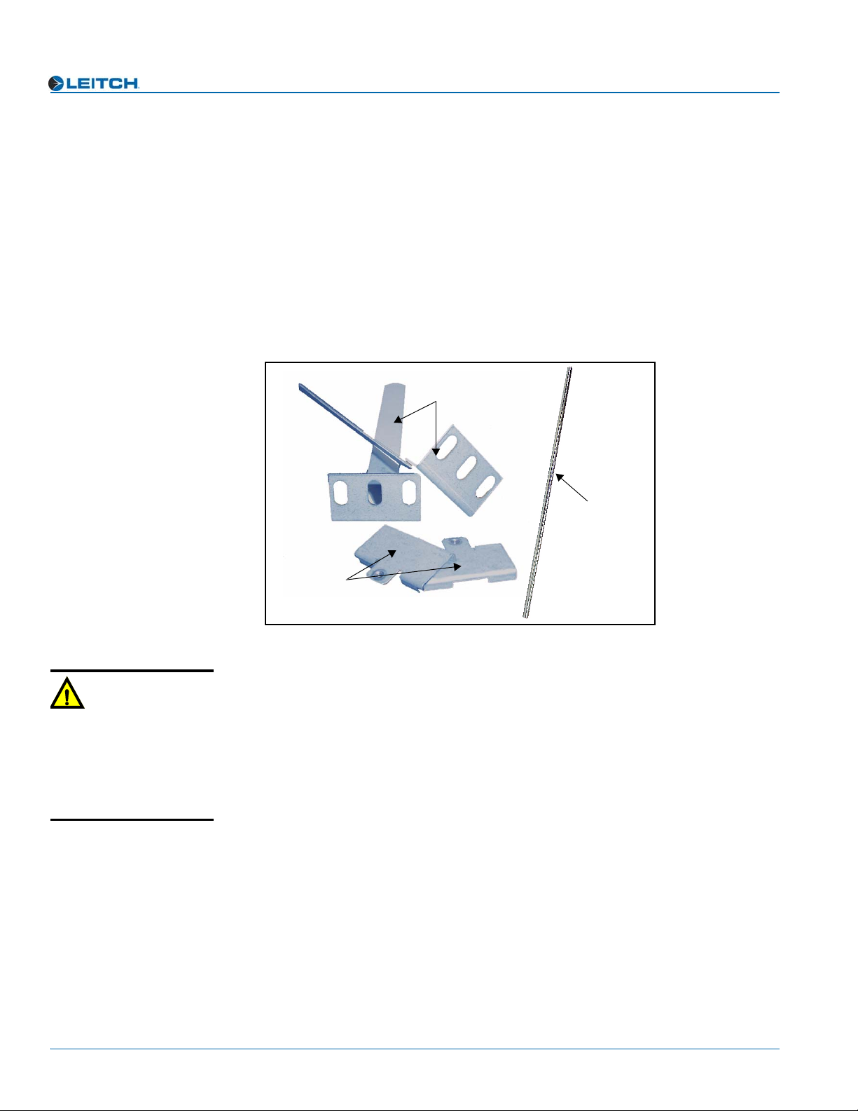
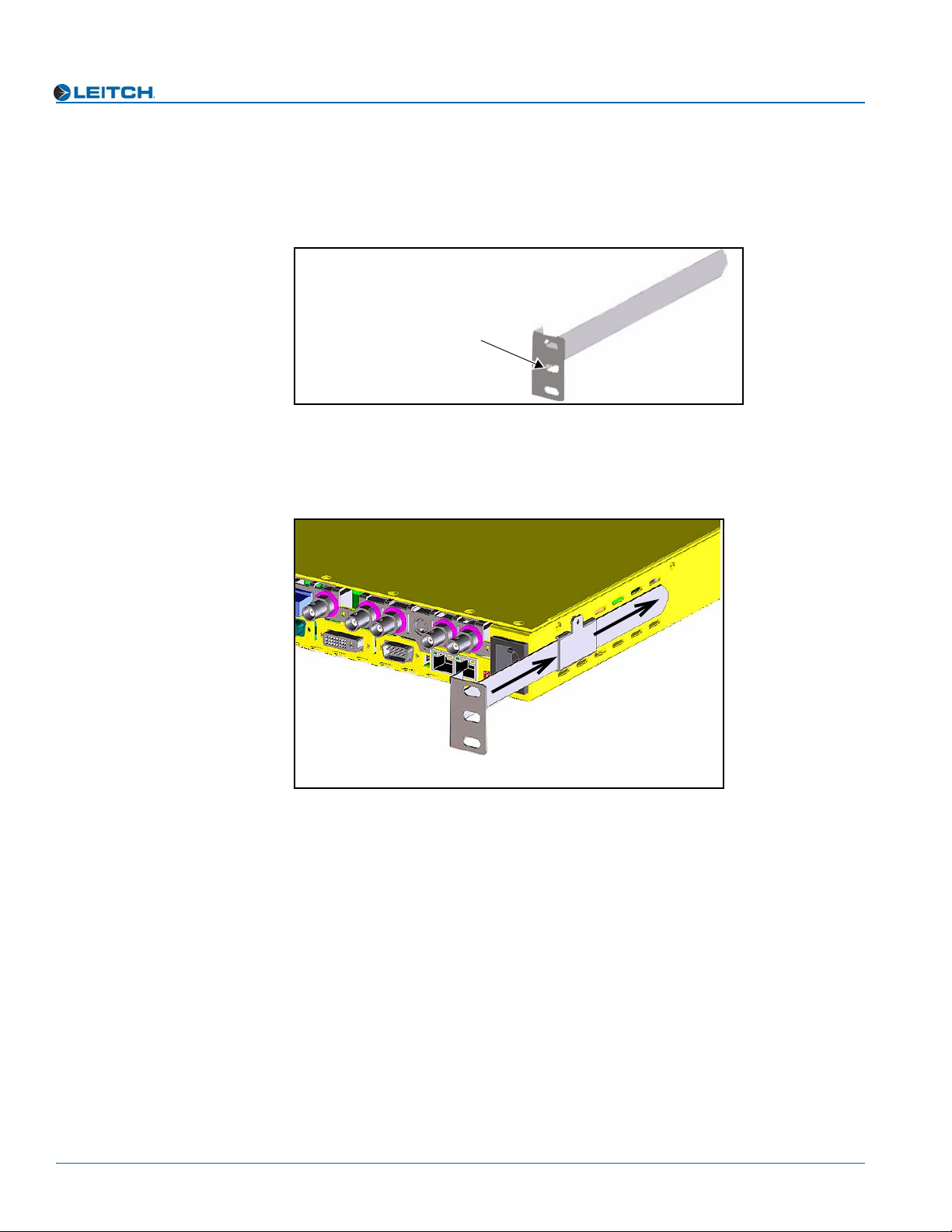
2. Install the X75 in a rack and make the required system connections (see Chapter 4:
“System Installation and Connections” in your X75SD/X75HD Multiple Path
Converters and Frame Synchronizers Installation and Operation Manual for
details).
3. Plug the unit into a grounded electrical source to turn it on.
The unit is factory configured with default settings, including the following network
settings:
• IP address of X75 system: 192.168.100.250
• Subnet mask: 255.255.255.0
• Gateway: 192.168.100.250
• Machine name: Leitch X75
(Upon request, Leitch can preconfigure X75 systems with specific IP addresses and
network settings. A request for factory configuration of network settings must be
placed at the time of order. Please contact your Leitch customer service
representative for more details.)
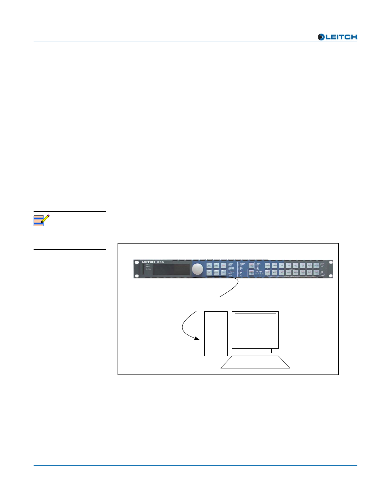
4. Using a frame-mounted local control panel (LCP), configure the network settings
for each system: assign a unique IP address to each unit, configure the subnet mask
to be the same for all units on a shared network, and change the gateway if required.
Network settings are done in within the Setup menu (see “Configuring Network
Settings” on page 10 for details).
5. If you are controlling the unit remotely via RCP, make the required Ethernet
connections (see “Remotely Controlling X75 Systems” on page 13 for details).
6. If you are controlling the unit via a third-party Web browser, launch the Web
browser (see “Configuring for HTTP Control (via Web Browser)” on page 15 for
details).
7. Configure your video (and audio) input settings prior to operation (see
“Configuring Video” on page 16 and “Configuring Audio” on page 17 for details).
Note
The current system IP address
and network settings can be
viewed on a local or remote
panel VFD screen.