E-5
PREFACE
This Operator’s Manual is meant for personnel that are operating the
machine and are responsible for its daily maintenance.
Kindly read this manual fully prior to starting work.
Such instructions as are related to your safety and/or that of
others are marked in the margin by a warning triangle with
exclamation mark. These instructions should be observed with
particular care and attention.
Instructions which may lead to serious material damage in case
of non-compliance or incorrect use are marked in the margin by
an exclamation mark.
The machine described in this manual may contain components
which do not form part of the standard equipment but are available
as optional extras.
This is not made clear in all cases, because standard specifications
may differ from country to country.
Furthermore, machines and optional extras may be adjusted to
specific regional conditions whilst they are also subject to
permanent research and innovation.
For this reason, the specifications of your machine may not be
consistent with the pictures in this manual.
WARRANTY CONDITIONS
For those parts which fail in normal operating conditions the factory
will make replacement parts available, free of charge, for a period of
12 (twelve) months from the date of purchase.
Warranty shall not apply if the instructions mentioned in this manual
have not been met, or if they have not been met completely or
correctly.
Neither shall warranty apply in case of modification of the machine
by you or third parties without our foreknowledge and/or
authorisation.
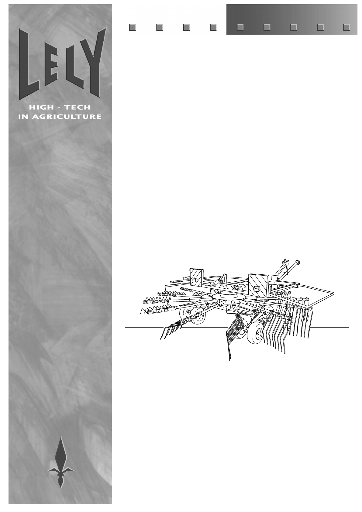
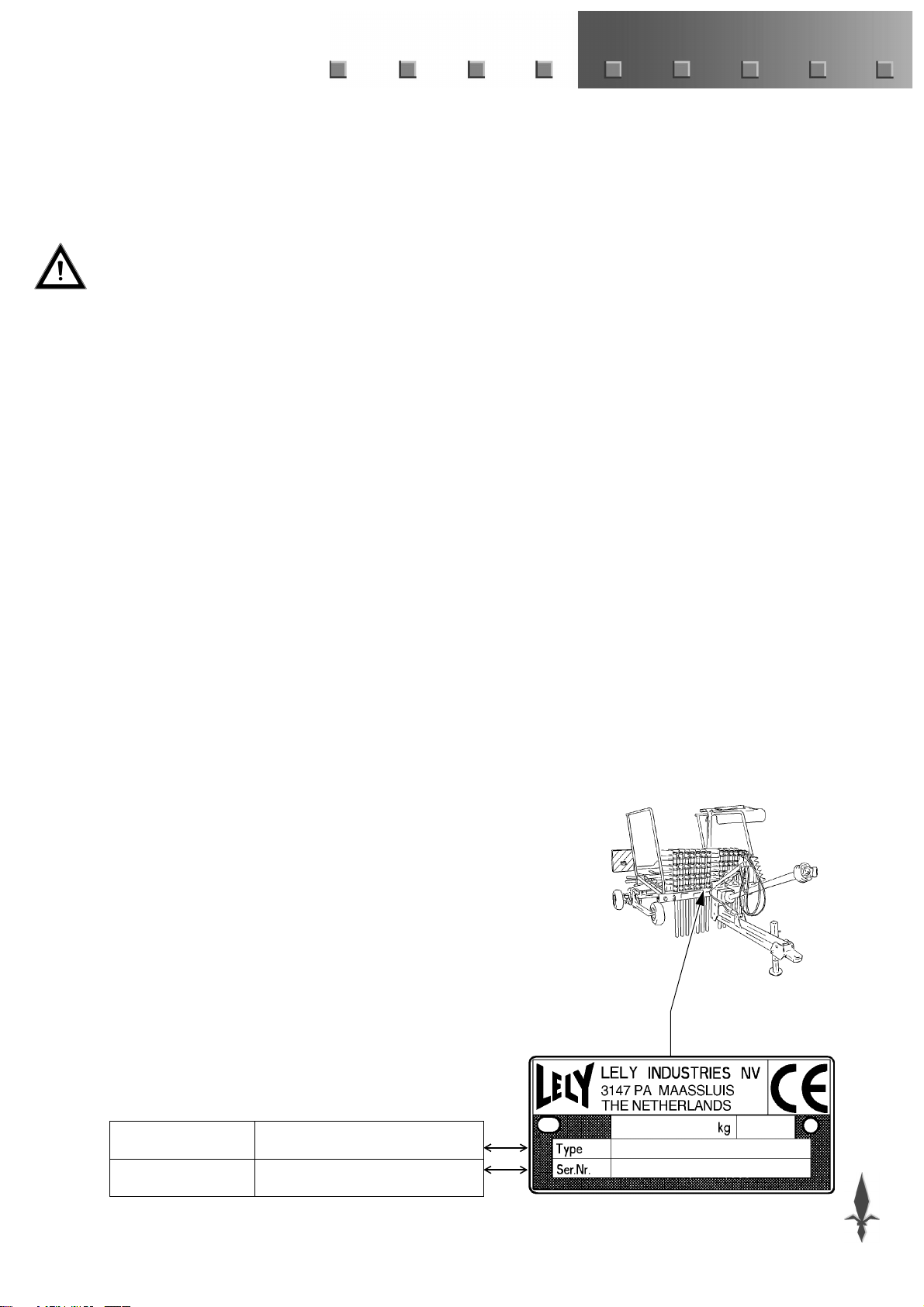
TYPE- AND SERIAL NUMBER OF YOUR
MACHINE
The type and serial number plate is fitted to the front of the storage
rack for the tine arms.
In case of correspondence and ordering of spare parts, kindly state
the type- and serial number of your machine.
Complete the box below with these numbers.
Type number
Serial number