LELY SPLENDIMO MC Series User manual

OPERATOR’S MANUAL
www.lely.com
SPLENDIMO MC
E-HV.014.0304
SPLENDIMO 320 MC


E-1
OPERATOR’S MANUAL
SPLENDIMO MC
Ehe014tp-d.fm
English
SPLENDIMO®is a registered trademark. The right of exclusive use belongs to the companies of the LELY Group.
©2004. All rights reserved. Nothing of this publication may be reproduced and/or published by printing, photocopying,
microfilm or any other way without the prior written permission of LELY INDUSTRIES N.V..


E-3
TABLE OF CONTENTS....................................................................................................page
PREFACE.......................................................................................................................5
WARRANTY CONDITIONS............................................................................................5
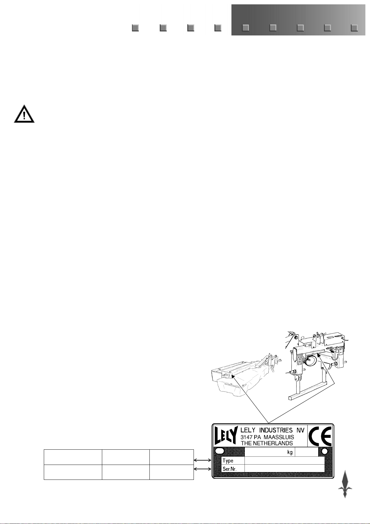
TYPE- AND SERIAL NUMBER OF YOUR MACHINE ...................................................5
SAFETY INSTRUCTIONS..............................................................................................6
EXPLANATION OF SAFETY DECALS ON THE MACHINE..........................................7
1 INTRODUCTION ............................................................................................................8
2 MOUNTING BEHIND THE TRACTOR ...........................................................................9
3 TRANSPORT.................................................................................................................10
4 MACHINE ADJUSTMENTS...........................................................................................11
4.1 Mowing height......................................................................................................11
4.2 Intensity of conditioning.......................................................................................11
4.3 Ground pressure..................................................................................................12
4.3.1 Mechanical ground pressure relief ............................................................12
4.3.2 Hydraulic ground pressure relief................................................................12
4.4 Swath width .........................................................................................................12
5 OPERATING THE SPLENDIMO® MC..........................................................................13
6 DISMOUNTING FROM THE TRACTOR.......................................................................14
7 MAINTENANCE.............................................................................................................15
7.1 Maintenance after operations ..............................................................................15
7.2 Lubrication...........................................................................................................15
7.3 Intermittent maintenance .....................................................................................16
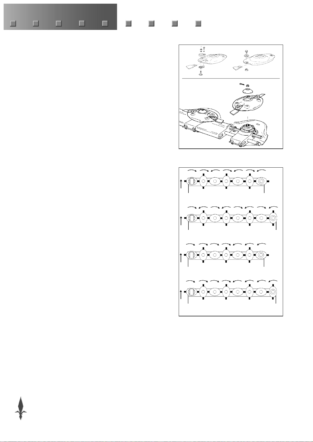
7.4 Replacement of knives ........................................................................................18
7.5 Change of oil in gearboxes..................................................................................18
7.6 Change of grease in mower elements.................................................................19
Supplements:
A REPAIRS TO THE CUTTER BAR.................................................................................20
A.1 Cutter bar assembly/disassembly........................................................................20
A.2 Replacement of the disc on the drive element.....................................................22
B CONDITIONER ADJUSTMENTS..................................................................................23
B.1 Position of top hood.............................................................................................23
B.2 Moving the conditioning rotor...............................................................................23
B.3 Rotor speed.........................................................................................................24
C HYDRAULIC GROUND PRESSURE RELIEF SYSTEM...............................................25
C.1 Scheme................................................................................................................25
C.2 Adjustment of minimum system pressure............................................................26
C.3 Trouble shouting..................................................................................................27
D OPTIONAL EXTRAS .....................................................................................................28
E TECHNICAL DETAILS...................................................................................................30


E-5
PREFACE
This Operator’s Manual is meant for personnel that are operating the
machine and are responsible for its daily maintenance.
Kindly read this manual fully prior to starting work.
Such instructions as are related to your safety and/or that of
others are marked in the margin by a warning triangle with
exclamation mark. These instructions should be observed with
particular care and attention.
Instructions which may lead to serious material damage in case
of non-compliance or incorrect use are marked in the margin by
an exclamation mark.
The machine described in this manual may contain components
which do not form part of the standard equipment but are available
as optional extras.
This is not made clear in all cases, because standard specifications
may differ from country to country.
Furthermore, machines and optional extras may be adjusted to
specific regional conditions whilst they are also subject to
permanent research and innovation.
For this reason, the specifications of your machine may not be
consistent with the pictures in this manual.
WARRANTY CONDITIONS
For those parts which fail in normal operating conditions the factory
will make replacement parts available, free of charge, for a period of
12 (twelve) months from the date of purchase.
Warranty shall not apply if the instructions mentioned in this manual
have not been met, or if they have not been met completely or
correctly.
Neither shall warranty apply in case of modification of the machine
by you or third parties without our foreknowledge and/or
authorisation.
TYPE- AND SERIAL NUMBER OF YOUR
MACHINE
The type/serial number plate is fitted to the arm of the break-back
device. The conditioning unit of the SPLENDIMO 320 MC mower
also has a separate type and serial number.
In case of correspondence and ordering of spare parts, kindly state
the type- and serial number of your machine.
Complete the box below with these numbers.
Type number
Serial number
!

E-6
SAFETY INSTRUCTIONS
- Use the machine only for the purpose for which it was designed.
- Follow all prevailing safety regulations, including those laid
down in this manual and occurring on the machine.
- Operate this machine in a safe way.
- The machine should be operated by authorised persons only.
- Be alert and observe all safety precautions.
- Make sure that all safety guards and protection devices are in
place.
- Keep out of reach of moving parts.
- Stop engine, PTO and moving parts before adjusting, cleaning or
lubricating the machine.
- Take care that nobody will be within the dangerous zone while the
machine is in operation and be sure that people are kept well away
from the machine. This is especially important when working
along roads and near or on fields that are accessible to the public.
- Use always a tractor with a cab.
- Clear the field of objects that could be thrown up by the machine.
- Observe the prevailing legislation for public road transport.
- Use flashing lights or other safety signs, when required.
- Don’t stand on the machine.
- Use genuine LELY parts only.
- Remove the pressure from hydraulic systems before starting work
on them and/or before coupling/ uncoupling hydraulic hoses.
- Use protective clothing, gloves and/or safety glasses if required.
- Clean the safety decals regularly so that they can be read at all
times.

E-7
EXPLANATION OF SAFETY DECALS ON
THE MACHINE
-Carefully read operator’s manual before handling the machine.
Observe instructions and safety rules when operating.
-Attention! Moving parts.
Stay clear of rotating machine parts.
-Danger of flying objects.
Maintain a sufficient, safe distance from the machine as long as
the tractor engine is running.
-Danger of mower knives.
Maintain a sufficient, safe distance from the machine as long as
the tractor engine is running.
-Danger of cutter bar dropping down.
Keep away from the cutter bar movement area.
- Never exceed the maximum PTO speed which is obligatory
for the machine.
-Danger of getting jammed by moving parts.
Keep out of reach of all parts as long as they have not yet been
blocked, or are otherwise prevented from moving.
-Danger of moving parts!
Read the operating instruction of the PTO shaft.
Never use a PTO shaft without protection.

E-8
1 INTRODUCTION
The LELY SPLENDIMO MC is a mower conditioner for mowing
on grasslands. A characteristic feature of the SPLENDIMO MC
mower conditioner is the central attachment of the conditioner unit
allowing optimum ground contour following.
Mowing on slopes up to approx. 20 up and 20 down is within the
machines capability.
The machine is built up of a cutter bar and a conditioner unit.
The cutter bar is fitted with type N or S discs (fig. 1). The cutter bar
is composed of cutting units according to the modular Lely system.
These elements as well as the intermediate spacers are torqued
together by a connecting rod.
The first cutting unit is driven from the top. A springsteel shaft,
which is driven from the first cutting unit, drives the other units of
the cutter bar.
Cutting units rotate either to the left or right. Standard
configurations are shown in fig. 2.
If required, the cutting units of the mowers with S model discs can
be fitted in a different configuration (depending upon the
combination of disc/ knife).
The conditioner unit comprises of a rotor fitted with fingers made of
an impact-resistant synthetic material, a metal hood with
swathboards as well as a crop inlet plate for adjustment of
conditioning intensity.
The conditioner unit operates over almost the full cutting width.
Crop treatment is such that patches of the waxy layer on the stem are
removed and that thick stems are broken. The crop is slightly turned
and laid down behind the machine in an airy, narrow swath. There
is a minimum contact between the crop and the moist field and there
is no need to drive on mown crops.
The SPLENDIMO MC mower can be controlled with just one
hydraulic ram. Ground pressure relief can be adjusted by altering the
stop pin of the spring set or by setting the pressure in the hydraulic
system to a different value or by setting the hydraulic system to a
different pressure level.
A breakback device prevents damage to the machine if an obstacle
is hit.
1
“N” “S”
2
SPLENDIMO 280 MCN
SPLENDIMO 320 MCN
SPLENDIMO 280 MCS
SPLENDIMO 320 MCS

E-9
2 MOUNTING BEHIND THE TRACTOR
The headstock is fitted with double linkage pins (categoryII) giving
two linkage possibilities (fig. 3) and allowing adjustment of the
offset position of the machine behind the tractor.
Depending on the method of mowing, the machine is positioned
directly next to the tractor tyres, or offset to a certain extent. When
combined with a front mower, the rear mower should be so adjusted
that a sufficient overlap is ensured. If the tractor has category III
linkage points, the linkage pins should be so fitted that the category
III sides are pointing outwards.
- Choose the position whereby the drive element is removed totally
beyond the tractor track. Take care that the tractor tyres do not
drive across the mown swaths during the following working
passes.
Always use position dwhen mowing down a descending slope
so that you can operate as far from the side as possible.
- Adjust the tractor 3 point hitch lower arms at equal height.
- Fit the lower arms to the linkage pins of the machines headstock.
- Fit the tractor top link to the machine by means of a category II or
III top link pin.
- Lift the headstock to such an extent that the pivot pin of the main
shaft (fig. 4) is approx. 70 cm over ground level.
- Place the parking jack in the raised position.
- Secure the tractor lever arms by means of stabilisation chains or
rods keeping the machine from making sideward movements.
- Check if the PTO shaft telescopes smoothly.
- Mount the PTO shaft to the tractor PTO.
At first assembly or use of another tractor: check the minimum
and maximum overlap of the PTO halves*.
- Fit the safety chain of the protection tube to a rigid part of the
tractor.
For mechanical ground pressure relief:
- Connect the hydraulic hoses to a double acting hydraulic tractor
valve with floating position.
Maximum allowed oil pressure: 21,0 MPa (210 bar).
For hydraulic ground pressure relief:
- Connect the hydraulic hoses with the blue mark to a double acting
hydraulic tractor valve.
Maximum allowed oil pressure: 21,0 MPa (210 bar).
- Connect the hydraulic hose with the white mark to a single acting
hydraulic tractor valve with floating position.
Maximum allowed oil pressure: 21,0 MPa (210 bar).
*. Consult the instruction supplied with the PTO shaft
3
d
c
4
70 cm
!

E-10
- Place the end of the control cord for locking the ram in the tractor
cab.
SPLENDIMO MC mower with mechanical ground pressure relief:
- Raise the machine with the lifting device of the tractor and the
hydraulic valve in the floating position until the retaining pin can
be removed from the sliding frame in front of the springs (fig. 5).
Place the retaining pin in the storage hole in the sliding frame.
- Check if the lever arms remain at an equal height when the cutter
bar is folded up.
3 TRANSPORT
The SPLENDIMO MC mower can be transported on the tractor’s 3-
point hitch.
Put the machine into the transport position as follows:
- Pull the operating cord of the cylinder lock to raise the lock hook
or to open the valve of the hydraulic system (fig. 6).
- Actuate the double acting tractor valve and retract the ram
completely.
When folding the machine from the headland position, the mower
conditioner may first descend before being lifted, which is due to
pressure fluctuations.
- While driving with the machine in transport position, the
transport lock should always be closed (fig. 7 by means of the
locking hook or the valve).
- Check if the ram is secured by the locking hook or close the valve.
- Use all such lighting and warning signals as are mandatory by
law (or other regulations prescribed by the authorities).
- For transport on public roads: make sure that the front axle
weight is sufficient (fit front weights, if necessary) and that the
rear axle weight allowed as a maximum is not needed.
The machine is now ready for transport.
Never allow the PTO shaft to rotate when the machine is in the
transport position.
5
6
7
!

E-11
4 MACHINE ADJUSTMENTS
Put the machine into the working position as follows:
- Open the valve on the ram (fig. 7).
- Pull the operating cord of the cylinder lock to raise the lock hook
or to open the valve of the hydraulic system (fig. 6).
- Actuate the double acting tractor valve and carefully extend the
machine fully.
- Use the hydraulic tractor lift to adjust the centre line of the pivot
pin of the main shaft at a height of 70 cm above ground level
(fig. 4). Take tractor wheelings into account.
If mowing on slopes is required, adjust the headstock higher to
ensure sufficient clearance around the central pivoting point of
the machine.
- Limit a downward movement with, for example, a stabilisation
chain if it is impossible to maintain the adjusted height of the
tractor hitch.
The machine is now ready for operating.
4.1 Mowing height
- Adjust the mowing height by adjusting the forward inclination of
the cutter bar with the aid of the top link (fig. 8).
4.2 Intensity of conditioning
The intensity of conditioning can be adjusted by means of the
conditioners crop inlet plate (fig. 9), the rotor speed and the position
of the conditioner and its top hood.
- Adjust the crop inlet plate.
Position A ensures the highest intensity of conditioning, whereas
it is lowest when the crop inlet plate is adjusted to the B position.
There are two intermediate positions.
If the adjustment of the conditioners crop inlet plate does not allow
sufficient possibilities to let the crop flow through, the position of
the rotor and plating may be adjusted. Please refer to supplement B
for a detailed description of this adjustment.
8
9
A
B

E-12
4.3 Ground pressure
The ground pressure of the SPLENDIMO MC mower is set either
with the mechanical ground pressure relief system using a spring
packet or with a hydraulic ground pressure relief system.
If, during operations, the cutter bar has a tendency to float which
inhibits proper ground contour following, then the pressure in the
relief system should be adjusted at a lower level.
4.3.1 Mechanical ground pressure relief
- Set the ground pressure using the stop pin (fig. 10). The
uppermost hole indicates the lowest ground pressure, the lower
hole the highest ground pressure.
4.3.2 Hydraulic ground pressure relief
- Follow the instructions below to set the ground pressure relief
system:
• Read the pressure on the gauge A (fig. 11);
• Pressurise the double acting tractor valve;
• Open and close the valve of the hydraulic system by means of
the cord until the required pressure has been achieved;
Should the pressure move the wrong way (up instead or down
or v.v.), then actuate the double acting valve in the opposite
direction.
The adjustment is not affected by lifting the machine on headlands.
The pressure within the system remains unchanged as long as the
valve is not opened.
On level fields, an adjustment at 7,0 MPa (70 bar) usually provides
an effective machine operation.
In the factory, minimum ground pressure of the machine is adjusted
at 5,0 MPa (50 bar). Under normal circumstances there is no need to
adjust this factory setting. Should the need for adjustment arise all
the same, please refer to supplement C.2 for an explanation.
Descending speed
The speed of descending for operating the machine on headlands
can be adjusted.
- Adjust this descending speed by turning the blue button B
(fig. 11) on the back of the protection cover.
turn right = descending slower.
turn left = descending faster.
4.4 Swath width
Swath width of the SPLENDIMO 280 MC mower is adjustable from
1,2 up to 2,8m; for the 320 MC model it can be varied between 1,4
and 3,0 m.
- Use the adjusting device A (fig. 12) to obtain the required opening
of the swath-board. Then lock the adjusting device.
- Adjust the swath board extensions B (standaard op SPLENDIMO
320 MC) to ensure a narrower swath.
10
11
A
B
12
A
B

E-13
5 OPERATING THE SPLENDIMO®MC
• Make sure that nobody is near the machine at the moment
the PTO is engaged.
• Do not allow anyone to come within a 100 m radius from the
machine during work.
• Stop the tractor engine before leaving the tractor cab.
• The safety covers, canopies and plating (fig. 13) are
essential protective components of the machine. So: operate
the mower only with these components duly fitted.
•Always operate with the safety cover folded down. Secure
the frames firmly in the clamp blocks (fig. 13).
To raise the machine when making a headland turn, the hydraulic
cylinder must be retracted using the double-action valve of the
tractor (for mechanical ground pressure relief) or only the single-
action valve of the tractor (for hydraulic ground pressure relief)
Lifting of the machine will stop automatically at an inclined position
of approx. 20° up (fig. 14).
The following directions should be followed for operating the
machine:
- Lower the machine by means of the hydraulic ram until it is just
above crop level.
- Engage the PTO shaft at the lowest possible engine speed.
- Rev up PTO speed up to 540 or 1.000 RPM which is the
maximum RPM allowed during work.
- Lower the machine into the crop.
- Ensure the floating position of the hydraulic valve; the rams have
to telescope smoothly throughout the operation.
- Do not drive too slowly. Effective working speeds start at approx.
8km/h. A lower speed may affect crop flow- through across the
cutter bar.
- Make sure that the PTO speed of 540 or 1.000 r.p.m. is maintained
during work.
A (temporary) drop of speed may cause crop entanglement in the
cutter bar and/or winding of long crop material underneath the
discs.
- First, lift the machine from the crop and then reduce the PTO
speed immediately.
13
14
!

E-14
- If the machine needs to be placed in the transport position at the
end of its operation: wait until all moving parts have come to a
standstill.
When folding up a machine with rotating parts, serious
damage may be incurred by the PTO shaft.
Please also be referred to chapter 3 “Transport”.
- If the machine does not follow the ground contours effectively, or
if it tends to dig into the ground, the machines ground pressure
should be adjusted (see § 4.3).
Closing the crop inlet plate increases the speed of the crop allowing
the swath boards to control swath more effec- tively (narrower).
Should the machine hit an obstacle during mowing, it can move
backward thanks to the extension of the breakback device (fig. 15).
After extension of the breakback device: drive backwards a few
meters until the breakback device has locked back into position.
The machine is protected against overload by a slip clutch.
6 DISMOUNTING FROM THE TRACTOR
- Lower the machine.
- Set the parking jacks in the lowest position.
SPLENDIMO MC mower with mechanical ground pressure relief:
- Raise the machine with the lifting device of the tractor and the
hydraulic valve in the floating position until the retaining pin can
be placed in the sliding frame in front of the springs (fig. 16).
- Lower the three point hitch until the parking jacks are supported
by the ground.
- Switch off the tractor engine. Disengage the PTO shaft from the
tractor PTO.
- Place the PTO shaft in the hook.
SPLENDIMO MC mower with hydraulic ground pressure relief:
- Set the hydraulic tractor valves in the floating position. By
operating the handle that protrudes from the hood (fig. 17) you
can relieve the pressure of the hydraulic system. The pressure
value to be indicated by the gauge should be 0 bar.
Adjust the descending speed at a higher value by means of the
blue turning button in case the pressure does not drop at all, or
only very slowly (attention: this will accelerate the speed of
descending during operations - see § 4.4).
- Remove the control cord for the hydraulic system from the tractor
cab.
- Disconnect the hydraulic hoses.
- Disengage the top link from the machine.
- Uncouple the lower arms from the machine.
15
16
17
!

E-15
7 MAINTENANCE
• Correct machine servicing is necessary with a view to
reliable and safe working.
• Install supports underneath the cutter bar if itis lifted from
the ground, and you intend to carry out work to the
machine.
7.1 Maintenance after operations
- Clean the machine thoroughly. After jet-cleaning allow for a few
moments rotation of the discs so that the water is swept away.
- Check the mower knives and discs for tightness and damage
(torque: see § 7.3).
- Check the safety cover for damage.
- Grease the machine with a rust preventive.
- Grease the piston rods with an anti-corrosion agent if a longer
period of inactivity is anticipated.
- Remove the agent when putting the machine back into operation.
If not, sealing of the ram may be affected after hardening of the
anti-corrosion agent.
7.2 Lubrication
- PTO shaft to be greased every 8 working hours by the grease
nipples on the cross assemblies, protection tubes and free wheel
clutch (fig. 18).
- Profiled tubes of the PTO shaft to be greased every 8 working
hours (fig. 18).
- Grease the bearing blocks (fig. 19) of the conditioner rotor every
8 working hours.
- Grease the pivoting points of the ram and support arm every 40
working hours (fig. 20).
- Apply a few drops of oil to the cams of the breakback device
every 40 working hours (fig. 21).
- Grease or lubricate all remaining pivot points every 40 working
hours.
8h
8h
18
8h
8h
19
8h

E-16
7.3 Intermittent maintenance
Intermittent maintenance has to be carried out:
• at the start of the mowing season;
• before prolonged storage of the machine;
• when the machine is used extensively during the season.
- Grease all points of the machine listed in § 7.2 ‘Lubrication’.
- Grease the spring-loaded locking pins of the yoke lock of the PTO
shaft.
- Check if the PTO shaft telescopes smoothly.
A damaged PTO shaft may cause excessive wear and tear to the
machine and tractor.
- Check correct pretension of 160 mm of the spring of the
breakback device (fig. 21).
The SPLENDIMO 320 MC mower has, in lieu of the spring, a
rubber block which needs to be compressed up to a length of
95 mm.
- Check the V-belts for correct tension.
Dismount the V-belt housing. The tension should be such that
each V-belt can be pushed in, between the pulleys, approximately
10 mm by applying a force of 70 N (7 kg) (fig. 21).
It is recommended to depressurize the V-belts if the machine will
remain out of operation for a longer period of time.
- Check the condition of wear plates, mower discs and knives.
(Replacement of knives: see § 7.4.).
- Check the knife bolts for tightness (fig. 22).
Type “N”: Torque 50-60 Nm (5-6 kgm).
Type “S”: Lock bolts with Loctite 243 or use new bolts and
locking agent.
The torque is 50-60 Nm (5-6 kgm).
- Check the mower discs for tightness (fig. 21). Torque: 150 - 250
Nm (15-25 kgm). The split pin locking the castellated nut is not
allowed to protrude above the pressure piece.
Tip: it is not allowed to turn the nut back; keep turning until the
split pin can be fitted.
- Check the machine for damage and flaws.
- Check the gearboxes for oil leakage.
(Refreshment of oil: see § 7.5.)
20
40h
21
95 mm
10 mm
70 N (7 kg)
40h
22
150-250 Nm (15-25 kgm)
50-60 Nm (5-6 kgm)
50-60 Nm (5-6 kgm)
“N”
“S”

E-17
- Check all bolts and nuts for tightness.
Pay particular attention to the bolts which secure the skids and
wear plates (fig. 23).
When tightening loose bolts/nuts the torques listed below should
be applied.
- Convince yourself of the presence and undamaged condition of
all safety decals on the machine (fig. 24).
A (P/N 9.1170.0408.0)
B (P/N 9.1170.0407.6) -2x-
C (P/N 9.1170.0410.2) -2x-
D (P/N 9.1170.0419.4)
E (P/N 9.1170.0420.5)
F1 (P/N 9.1170.0125.4)
F2 (P/N 9.1170.0175.5)
G (P/N 9.1170.0437.1) -3x-
H (P/N 16.61.175) -2x-
M6 M8 M10 M12 M14 M16 M20 M24
Nm 10 25 50 85 135 215 410 710
kgm 1,0 2,5 5,0 8,5 13,5 21,5 41,0 71,0
23
24
A
BC D
E
FG
H
BC
H
AB
CD
EF1
G H
F2

E-18
7.4 Replacement of knives
The mower knives come in 2 different versions for discs with LH or
RH rotation. The front of the cutting edge has to point downward,
viewed in the direction of rotation of the disc (fig. 25).
The mower knives have two cutting edges. After one edge is worn,
the knife can be reversed so that the second edge can be used.
- Knives should always be replaced in pairs in order to keep the disc
balanced.
- Replace worn or damaged nuts and knife bolts.
- Type “N”:
Use new, self-locking nuts and tighten them with a torque of 50-
60 Nm (5-6 kgm).
- Type “S”:
Use new knife bolts together with a locking agent, or apply
Loctite 243 to the threaded part of the bolt.
Tighten the knife bolts with a torque of 50-60 Nm (5-6kgm).
7.5 Change of oil in gearboxes
Change the oil of the gearboxes and the drive element of a new
mower (or after assembly of a new gearbox) after approx. 30
working hours for the first time. After that, oil has to be changed
every 250 working hours.
- Fill the gearbox A (fig. 26) with 1,7 l GX85W-140 transmission
oil.
- Fill the gearbox B (fig. 27) with 0,85 l GX85W-140 transmission
oil.
- Fill the drive element C (fig. 27) with a carefully measured
quantity of 0,45 l GX85W-140 transmission oil.
An incorrect oil quantity may lead to overheating and
unrepairable damage of the gearbox and/or the drive element.
Change the oil more often when operating the machine in
extreme working conditions.
25
50-60 Nm (5-6 kgm)
50-60 Nm (5-6 kgm)
26
A:
1,7 l
27
B: 0,85 l
C: 0,45 l
!
This manual suits for next models
6
Table of contents
Other LELY Lawn Mower manuals