LELY CENTERLINER S User manual

CENTERLINER
S/SL
A-HV.014.1198
OPERATOR'S MANUAL
CENTERLINER S


OPERATOR’S MANUAL
CENTERLINER S/SL
Ahe014-a
CENTERLINER S®, CENTERLINER SL®, CENTRONIC®and CENTERMATIC®are registrated trademarks.
The right of exclusive use belongs to the LELY companies.
©1998. All rights reserved. Nothing of this publication may be reproduced and/or published by printing,
photocopying, microfilm or any other way without the prior written permission of LELY INDUSTRIES N.V.


TABLE OF CONTENTS .................................................................................................page
PREFACE ..........................................................................................................................37
WARRANTY CONDITIONS .............................................................................................37
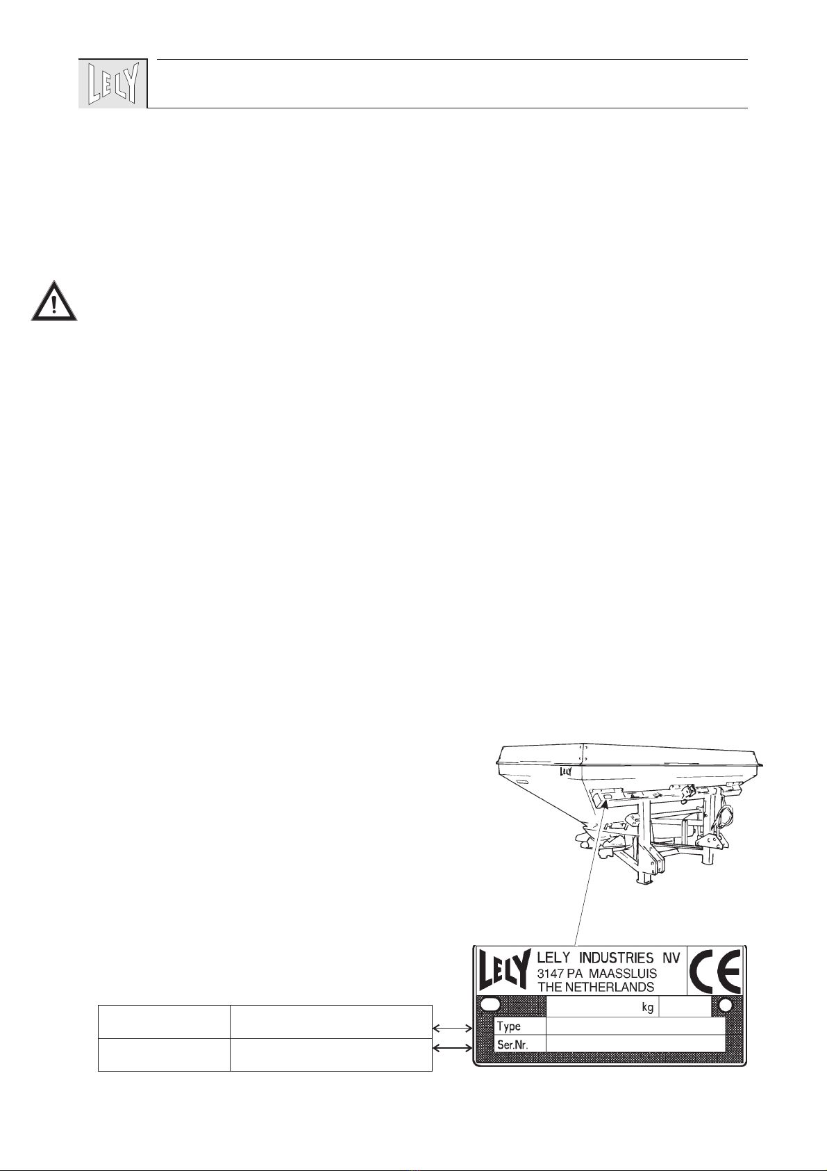
TYPE- AND SERIALNUMBER OF YOUR MACHINE...................................................37
SAFETY INSTRUCTIONS ...............................................................................................38
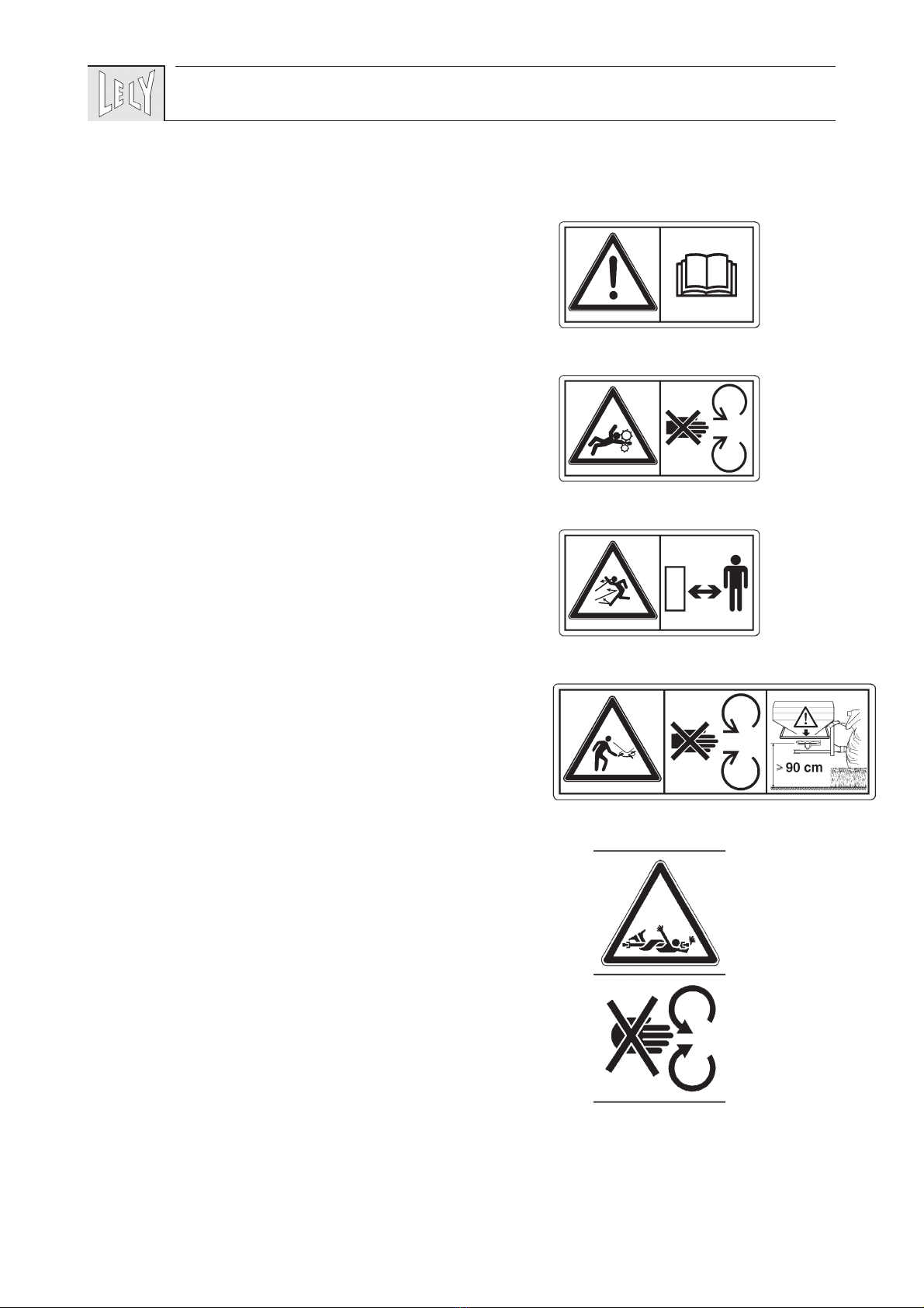
EXPLANATION OF SAFETY DECALS ATTACHED TO THE MACHINE ...................39
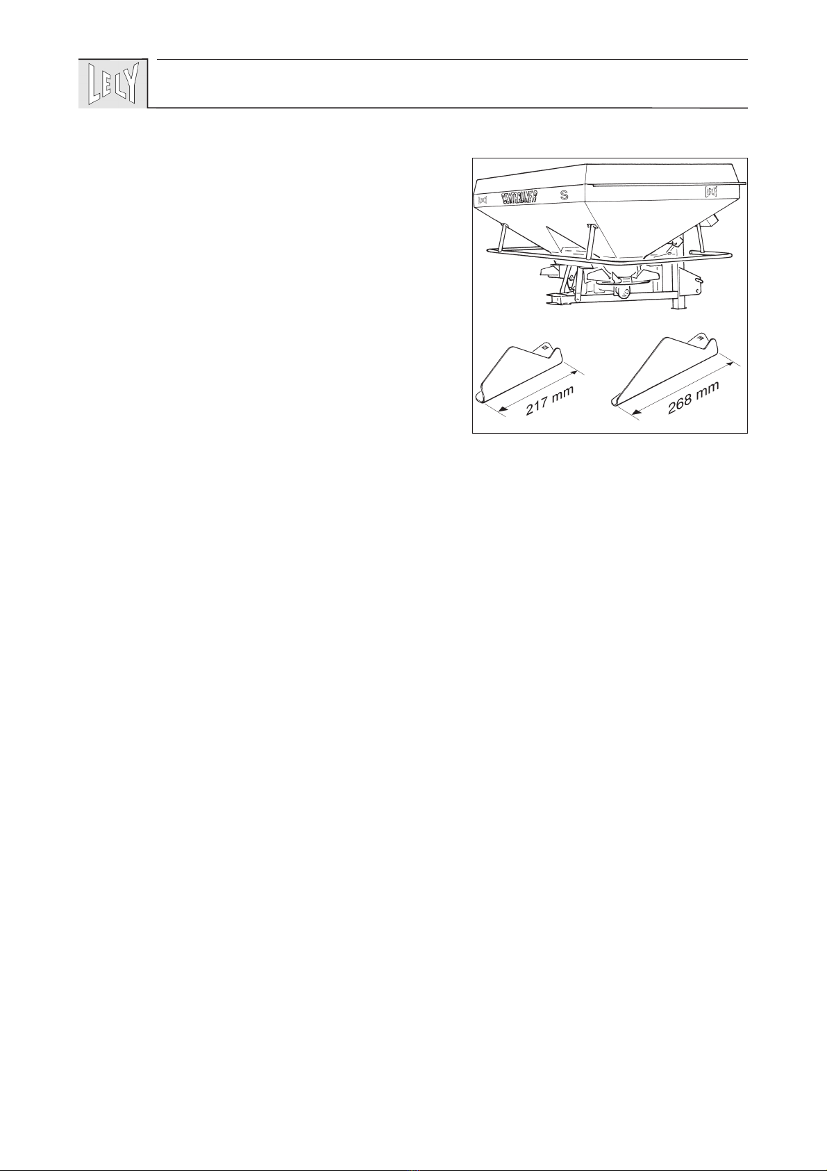
1 DESCRIPTION.............................................................................................................40
2 MOUNTING BEHIND THE TRACTOR ......................................................................42
3 TRANSPORT ...............................................................................................................43
4 MACHINE ADJUSTMENTS........................................................................................44
4.1 Output rates .......................................................................................................44
4.2 Spreading width.................................................................................................47
4.2.1 Spinner discs speed........................................................................................47
4.2.2 PTO output ...................................................................................................48
4.2.3 Forward inclination .........................................................................................49
4.3 Working height...................................................................................................49
4.4 Tilting for headland spreading.........................................................................50
5 WORKING WITH THE CENTERLINER®...................................................................51
5.1 Working with the CENTERLINER S/SL®........................................................51
5.2 Operation schedule...........................................................................................53
5.3 Check of spreading width ................................................................................53
5.4 Check of output rate .........................................................................................54
6 DISMOUNTING FROM THE TRACTOR ...................................................................55
7 MAINTENANCE ...........................................................................................................56
7.1 Maintenance after operation............................................................................56
7.2 Lubrication .........................................................................................................56
7.3 Intermittent maintenance .................................................................................57
Bijlagen
A CONDENSED OPERATING INSTRUCTIONS ...............................................61
B OPTIONAL EXTRAS.........................................................................................62
C TECHNICAL DETAILS ......................................................................................64
35


PREFACE
This Operator’s Manual is meant for personnel that are
operating the machine and are responsible for its daily
maintenance.
Kindly read this manual fully prior to starting work.
Such instructions as are related to your safety and/or that of
others are marked in the margin by a warning triangle with
exclamation mark. These instructions should be observed
with particular care and attention.
Instructions which may lead to serious material damage in
case of non-compliance or incorrect use are marked in the
margin by an exclamation mark.
The machine described in this manual may contain compo-
nents which do not form part of the standard equipment but
are available as optional extras. This is not made clear in all
cases, because standard specifications may differ from
country to country.
Furthermore, machines and optional extras may be adjusted
to specific regional conditions whilst they are also subject to
permanent research and innovation. For this reason, the
specifications of your machine may not be consistent with the
pictures in this manual.
WARRANTY CONDITIONS
For those parts which fail in normal operating conditions the
factory will make replacement parts available, free of charge,
for a period of 6 (six) months from the date of purchase.
Warranty shall not apply if the instructions mentioned in this
manual have not been met, or if they have not been met
completely or correctly. Neither shall warranty apply in case
of modification of the machine by you or third parties
without our foreknowledge and/or authorisation.
TYPE- AND SERIAL NUMBER OF
YOUR MACHINE
The type/serial number plate is fitted to the chassis beam at
the front of the machine.
In case of correspondence and ordering of spare parts, kindly
state the type- and serial number of your machine. Complete
the box below with these numbers.
37
!
type number
serial number

SAFETY INSTRUCTIONS
- Use the machine only for the purpose for which it was
designed.
- Follow all prevailing safety regulations, including those
laid down in this manual and occurring on the machine.
- Operate this machine in a safe way.
- The machine should be operated by authorised persons
only.
- Be alert and observe all safety precautions.
- Make sure that all safety guards and protection devices are
in place.
- Keep out of reach of moving parts.
- Stop engine, PTO and moving parts before adjusting,
cleaning or lubricating the machine.
- Take care that nobody will be within the dangerous zone
while the machine is in operation and be sure that people
are kept well away from the machine. This is especially
important when working along roads and near or on fields
that are accessible to the public.
- Use always a tractor with a cab.
- Clear the field of objects that could be thrown up by the
machine.
- Observe the prevailing legislation for public road transport.
- Use flashing lights or other safety signs, when required.
- Don’t stand on the machine.
- Use genuine LELY parts only.
- Remove the pressure from hydraulic systems before
starting work on them and/or before coupling/uncoupling
hydraulic hoses.
- Use protective clothing, gloves and/or safety glasses if
required.
- Clean the safety decals regularly so that they can be read at
all times.
38

EXPLANATION OF SAFETY DECALS
ATTACHED TO THE MACHINE
• Carefully read operator’s manual before handling the
machine. Observe instructions and safety rules when
operating.
• Attention! Moving parts.
Stay clear of rotating machine parts.
• Danger of flying objects.
Keep a sufficient, safe distance from the machine as long as
the tractor motor is engaged.
• Danger of rotating ejector discs. Maintain a safe distance.
If the ejector discs are adjusted at a height of 90 cm or more
from the ground, the machine has to be fitted with a
protection bracket.
• Danger of moving parts!
Read the instructions for the PTO shaft.
Never operate with a PTO shaft without safety guard.
39

1 DESCRIPTION
The LELY CENTERLINER S/SL is a fertilizer spreader
ensuring a particularly accurate application of fertilizers.
The distinguishing feature of the CENTERLINER S spreader
in respect of the CENTERLINER SL spreader is the different
length of the spoons fitted to the machine. The CENTER-
LINER S has shorter spoons than the CENTERLINER SL
(fig. 1).
Seen from the rear, the CENTERLINER spreader’s spinner
discs rotate to the inside. Each disc covers virtually the full
spreading width (fig. 2).
Consequently, the spreading patterns of both discs overlap
almost completely so that a symmetric pattern is obtained
centrally behind the tractor, irrespective of granular sizes.
During each consecutive passage the composite spreading
pattern of the previous passage is overlapped once more.
Thus, the eventual spreading pattern is made up by a 4-fold
composite pattern (fig. 3).
Because of its large working width, as well as the varying
working width of the S and SL version, the CENTERLINER
spreader is ideally suitable for following such tramlines as
were laid out in the crop.
Attention! Fertilizer granulars may attain high speeds. Keep
this in mind when you are spreading over soft crop.
For headland spreading the spreader only needs to be tilted
behind the tractor. As a result of this tilting, the composite
spreading pattern on the headland side is shrunk, so that the
full rate is applied in one passage. This passage is situated at
half the working width calculated from the headland side.
The CENTRASIDE headland spreading attachment (optional
extra) offers another method for spreading on headlands.
When using this facility, a sharply defined spreading pattern
is obtained on the RH side of the spreader. The first working
passage of a spreader fitted with a CENTRASIDE headland
spreading attachment is situated at approx. 2 m from the
headland side (fig. 4).
40
1
SSL
!

41
2
3
4
spreading pattern
LH ejector disc
spreading pattern
RH ejector disc
combined
CENTERLINER®
spreading pattern
½R R R
R = working width
spreading width
100 % 50 % + 50 % 50 % + ....
R= Working width R
2 - 2,5 m
CENTRASIDE®

2 MOUNTING BEHIND THE TRACTOR
Basic attachment AB. Other possibilities of coupling, whenever
necessary, are described further on in this manual.
- Adjust the tractor’s lever arms at equal height.
- Fit the lever arms to the CENTERLINER spreader by
means of Cat. II linkage pins. Place the linkage pin in the
upper hole (A, fig. 5) of the fixed linkage point.
- Mount the tractor’s top link to the CENTERLINER sprea-
der with the aid of a Cat. II top link pin. Fix the top link on
the tractor side in the highest position.
- Secure the tractor’s lever arms by means of stabilisation
chains or rods to prevent the machine from making lateral
movements.
- Check the PTO shaft for smooth telescoping.
- Mount the PTO shaft to the tractor PTO.
Before mounting the PTO shaft for the first time, or when
using another tractor, the minimum and maximum overlap
should be checked. Refer to the instructions supplied with the PTO
shaft.
- Fit the safety chain of the guard tube to a solid part of the
tractor.
- Connect the hydraulic hose to a double acting tractor valve.
- Extend the tilt ram and place the locking pin in hole B
(fig.5). Then retract the tilt ram again.
- If the machine has a mechanical shutter control, place the
control lever (fig. 6) in the fixation bracket in the tractor
cab.
- In case of a hydraulic shutter control (fig. 7): connect the
two hydraulic hoses to a double acting tractor valve.
42
5
6
7
A
C
D
B
!

3 TRANSPORT
The CENTERLINER spreader can be transported in the
tractor’s 3 point lift.
- Apply all such lighting and warning signals as are
mandatory by law.
- For transport on public roads care should be taken that the
front axle pressure is sufficient (fit front weights, if
necessary) and that the maximum rear axle pressure is not
exceeded.
The tractor is easier to control when the CENTERLINER
spreader’s hopper is empty. It is therefore recommended to
fill the hopper after arrival on the plot to be worked. This also
eliminates the kind of fertilizer compression that may occur
during transport.
It is possible to couple a trailed carriage to the CENTER-
LINER spreader’s chassis (fig. 8). In case of such an
attachment, the (total) weights allowed by law as a maximum
and further regulations should be taken into account.
Make sure never to couple a trailed carriage to the rear of the
CENTERLINER spreader when working with the CENTER-
MATIC weighing element! Horizontal load on the weighing
element may cause a permanent inaccuracy.
43
8

4 MACHINE ADJUSTMENTS
4.1 Output rates
The output rate is determined by the shutter position,
working width, forward speed and PTO output. The correct
position of the locking pin in the calibration scale can be
determined by means of the output rate charts.
The quantities listed in the output charts are approximative.
Size, shape and weight of the granulars may vary according
to the fertilizer brand and/or production batch. the particle
fractions of the fertilizer to be applied (fig. 11) should
therfore be compared to such fractions as are listed in the
output chart.
The effective output may also be affected by other circum-
stances (for example: air humidity).
It is therefore advisable to check the output ( see par. 5.4).
First determine the following values:
- The kind of fertilizer to be spread (X, if required, by means
of a grading kit)
- The required working width (R).
- The gear set (Z) which corresponds with R and, if
necessary, the forward inclination (H) from the working
width chart.
- The forward speed (V) depending on motor speed and
acceleration
- The required output rate per ha (Q).
44
9

Refer to the output chart which corresponds with the
established values R, Z, H, X and the pellet size calibration
(fig. 10).
Some output charts are valid for the CENTERLINER S
spreader fitted with 217 mm spoons, while others are valid
for the CENTERLINER SL spreader fitted with 268 mm
spoons.
- From the chart you will find the required output rate (Q)
under the column for the required forward speed (V).
- Read the value S in column most to the left. This value
corresponds with the shutter position to be used.
Example I:
• Fertilizer: X = Kas 27% N, Kemira
• Required working width:R=27m
• Required forward speed:V=8km/h
• Required output rate: Q = 475 kg/ha
Procedure:
• Refer to working width chart for establishing the values for
Z and H.
-> Z = 23/12,H=5°
• Refer to the output chart to be used.
• In the columnV=8km/h, you will find Q = 475 kg/ha.
-> S = 8A.
If spreading operations are carried out at a forward speed of 8
km/h, a working width of 27 m and a shutter position of 8A,
the output rate in the chart will be 475 kg/ha.
If the required output is situated between two consecutive
positions of the calibration scale, an intermediate position
can be set by placing the flattened end of the locking pin in
the calibration scale (fig. 11).
The fertilizer output is then set exactly between the quantity
at this position and the next higher position.
45
10
11
S
Q
V
Z, H
R
X

If the chart does not list the required forward speed, the
output at that specific speed can be calculated as follows.
- Divide the required forward speed by a forward speed from
the chart (6, 8, 10, 12 or 14 km/h) and multiply the outcome
with the output rate per ha to be spread.
- Consult the column for the used forward speed (6, 8, 10, 12
or 14 km/h) to find the outcome of the calculation and read
the value S in the column most to the left.
The value S and the required forward speed V give an output
rate Q per hectare.
Example II:
• Fertilizer: X = KAS 27% N, Kemira
• Required working width:R=27mm
• Required forward speed: V = 11km/h
• Required output rate: Q = 280kg/ha
Procedure:
• Consult the working width chart for values Z and H.
-> Z = 23/12,H=5°
• Refer to the output chart to be used.
• Divide 11 km/h by 6 km/h (speed from the chart) and
multiply the outcome by the required output rate 280 kg/ha.
-> 1,8 x 280 kg/ha = 515 kg/ha.
• Consult the column V = 6km/h, to find Q = 515 kg/ha
(fig. 12).
-> S = 7A. The locking pin should therefore be placed with
the flattened end in the calibration scale.
If spreading operations are carried out at a speed of 11 km/h,
a working width of 27 m and a shutter position of 7A with
flattened end, the output rate will be 280 kg/ha (according to
the chart).
There is no difference between the output setting for
headland spreading and full field operations.
46
12

4.2 Spreading width
4.2.1 Spinner discs speed
In order to obtain the correct spreading width at a given
working width, the spinner discs should rotate at the
appropriate r.p.m. Spinner speeds can be changed in two
ways: by means of change gears (fig. 13) and by adjusting the
PTO speed.
When adjusting the spinner disc speed by means of change
gears the PTO output should be 540 r.p.m.
(Please be referred to §4.2.2 PTO speed, if you wish to
operate at a PTO speed of 750 or 1.000 r.p.m.).
The correct gear sets are indicated in the output charts by
Z=gear set (top/bottom)
When opening the gearbox for changing gears, take care not
to damage the sealing.
Example:
According to the sample chart (fig. 10, 12) a gear set
Z = 23/12 (i.e. gearZ=23ontop/ gearZ=12below) should
be used at a working width of 27m.
The spinner disc speed can also be adjusted through the PTO
speed. The PTO output to be used can be calculated as
follows: NZ
ZPTO speed
bottom
top
´
=
N = spinner disc speed ( as per chart)
Zbottom = gear fitted below
Ztop = gear fitted on top
Example:
Fitted in the gearbox is a set 23/12 (top/bottom) and the
required spinner disc speed N = 810 (given in output chart).
The correct PTO speed=
810 12
23
´
= 423 r.p.m.
47
13

4.2.2 PTO speed
If so required, a PTO speed of 750 or 1.000 rather than 540
r.p.m. can be used. In that case another gear set than the one
listed in the output rate chart should be fitted.
Select the set that comes closest to the spinner disc speed
listed in the chart.
The chart below shows the spinner disc speeds for all
possible gear sets.
Use the lowest speed possible for obtaining the required
working width. A higher speed increases wear and tear of the
drive and the spoons. Soft crop may be damaged as well.
Do not use a gear set which is not listed in the chart. Do not
allow the spinner disc speed to exceed 1059 r.p.m. as a result
of an increased PTO speed.
If so required, a PTO speed of 750 or 1000 r.p.m. can be used
as a means for saving fuel. This can be achieved by reducing
the motor speed until the PTO shaft turns 540 r.p.m.
Example:
A PTO shaft turns 1000 r.p.m. at a motor speed of 2100 r.p.m.
For the PTO shaft to turn 540 r.p.m. in the same gear position,
the motor speed should be: 540 2100
1000
´= 1134 r.p.m.
48
CHANGE GEAR top 12 13 14 15 16 17 18 19 20 21 22 23
below 23 22 21 20 19 18 17 16 15 14 13 12
CENTERLINER S/SL®Spinner disc r.p.m.
PTO speed 540 r.p.m. 282 319 360 405 455 510 572 641 720 810 914 1035
PTO speed 750 r.p.m. 391 443 500 563 632 708 794 891 1000 - - -
PTO speed 1000 r.p.m. 522 591 667 750 842 944 1059 - - - - -

4.2.3 Forward inclination
The necessary forward inclination of the CENTERLINER
spreader is indicated in the output charts (H=..°).
- Park the tractor on a level floor (take wheelings into
account).
- Adjust the machine at working height by means of the
tractor hydraulics.
- Adjust the forward inclination by means of the top link.
The angle indicator on the chassis (fig. 14) shows the
machine’s forward inclination.
4.3 Working height
- Lift the CENTERLINER spreader so far that the spinner
discs are approx. 60 cm over the ground or crop level (fig.
15).
• Measure from the centre of the spinner disc with a
machine that was inclined forward
• Measure from the centre of the highest spinner disc with
a machine that was tilted for headland spreading.
Take tractor wheelings into account.
If fertilizer is thrown beyond the plot (in case of smaller
working widths and during headland spreading), the PTO
speed might be reduced and/or the working height lowered in
order to reduce the spreading width.
If, during headland spreading, the fertilizer remains before
the plot side, the spreading width can be adjusted by lifting
the CENTERLINER spreader slightly higher up.
Use the linkage CD (fig. 16) if the machine can not be lifted
high enough.
The spreader is then raised approx. 8 cm higher as compared
to the basic attachment AB.
When spreading over open crops through which the granulars
can still be (partly) projected, it may be necessary to reduce
the mandatory 60 cm spinner disc height over the crop level.
According to the crop density, adjust the height of the spinner
discs over the crop between 30 and 60 cm.
49
14
15
60 cm
16
CB AB CD AD
A
D
B
C

With a view to your safety, and that of others, the CENTER-
LINER spreader needs to be fitted with a protection bracket
A (fig. 17) if the spinner discs are adjusted at a height of
90 cm or more above ground level (top dressing).
During machine operations the distance between the spinner
discs and the ground is never allowed to exceed the maximum
of 145 cm.
4.4 Tilting for headland spreading
For headland spreading the CENTERLINER spreader has to
be tilted behind the tractor.
Unless you use the CENTRASIDE headland spreading attachment for your
headland spreading operation.
Headland spreading on the RH side of a plot:
• Extend the ram for adjustment of the locking pin.
• Apply the AD attachment (see fig. 16).
- Place the locking pin of the tumbler in hole D.
- Couple the RH tractor lever arm to the machine
(hole A) by means of the linkage pin.
• Retract the ram again.
Headland spreading on the LH side of a plot:
• Extend the ram for adjustment of the locking pin.
• Apply the CB attachment (zie fig. 16).
- Place the locking pin of the tumbler in hole B.
- Couple the RH tractor lever arm to the machine
(hole C) by means of the linkage pin.
• Retract the ram again.
- Check the forward inclination. Correct any changes resul-
ting from tilting by means of the top link.
- If too much fertilizer is thrown beyond the plot, it may be
necessary to adjust the working height of the spreader. The
best spreading pattern is achieved when approx. 7% is
thrown beyond the plot border.
If not accepted, use the CENTRASIDE headland spreading attachment
to obtain a sharply defined spreading pattern on the plot side.
50
17
A
>90 cm
max. 145 cm
This manual suits for next models
1
Table of contents
Popular Spreader manuals by other brands

Euro garden
Euro garden SP31510 quick start guide

Earth Way
Earth Way M80ECM Operation and assembly manual

Salt Dogg
Salt Dogg WB150BG Assembly instructions

Earth Way
Earth Way M80ECM Assembly instructions

OEM Tools
OEM Tools 26679 Operating instructions and parts manual

Earth Way
Earth Way M40 Operation and assembly manual