Lem Elettronica TXWBT User manual

Rel. 1.2
TXWBT
Optical Transmitter
User manual
ITALY
MADE IN
200 mm
150 mm
38 mm
Satellite integrated gain and slope adjustable amplifier
Terrestrial integrated gain adjustable amplifier
LNB and TV Terr. power feeding
Test and Monitor for each input
Optical monitor Led for each Laser
ON/OFF switch for each Laser
Double DC input for redundant power supply
OPTICAL TRANSMITTER TXWBT
RF SATELLITE INPUT n° 2
RF TERRESTRIAL INPUT 1
RF TEST OUTPUTS n° 3
OPTICAL OUTPUT n° 1
OPTICAL
OPERATION WAVELENGTH nm 1310 - 1330 - 1550
LASER TYPE UN-COOLED MULTI QUANTUM DFB
LASER CLASS 1M, EN 60825-1
OUTPUT POWER dBm 7 0/+0,3
OUTPUT CONNECTOR SC/APC
SATELLITE
INPUT BANDWIDTH MHz 250... 2.400
INPUT RANGE LEVEL (ADJUSTABLE) dBµV 70... 90
A.C.G. RANGE dB 20
SLOPE ADJUSTER RANGE dB 0... 9
RETURN LOSS dB >12
MAX. LNB REMOTE FEEDING 5W (340mA@14,5VDC)
TV TERRESTRIAL
INPUT BANDWIDTH MHz 80... 900
INPUT LEVEL FOR 32 MUX dBµV 70
INPUT LEVEL ADJUSTER RANGE dB 0... -15
MAX. TERRESTRIAL REMOTE POWER FEEDING 8W (550mA@14,5VDC)
OTHERS
DC INPUT VOLTAGE V12... 20
MAX. POWER CONSUMPTION W/O EXTERNAL LOAD 3,5W (240mA@15VDC)
MAX. POWER CONSUMPTION WITH EXTERNAL LOAD 17,2W (1150mA@15VDC)
SHORT-CIRCUIT PROTECTION ALL INPUTS
DIMENSIONS mm 135x200x38
OPERATING TEMPERATURE °C 0... +50

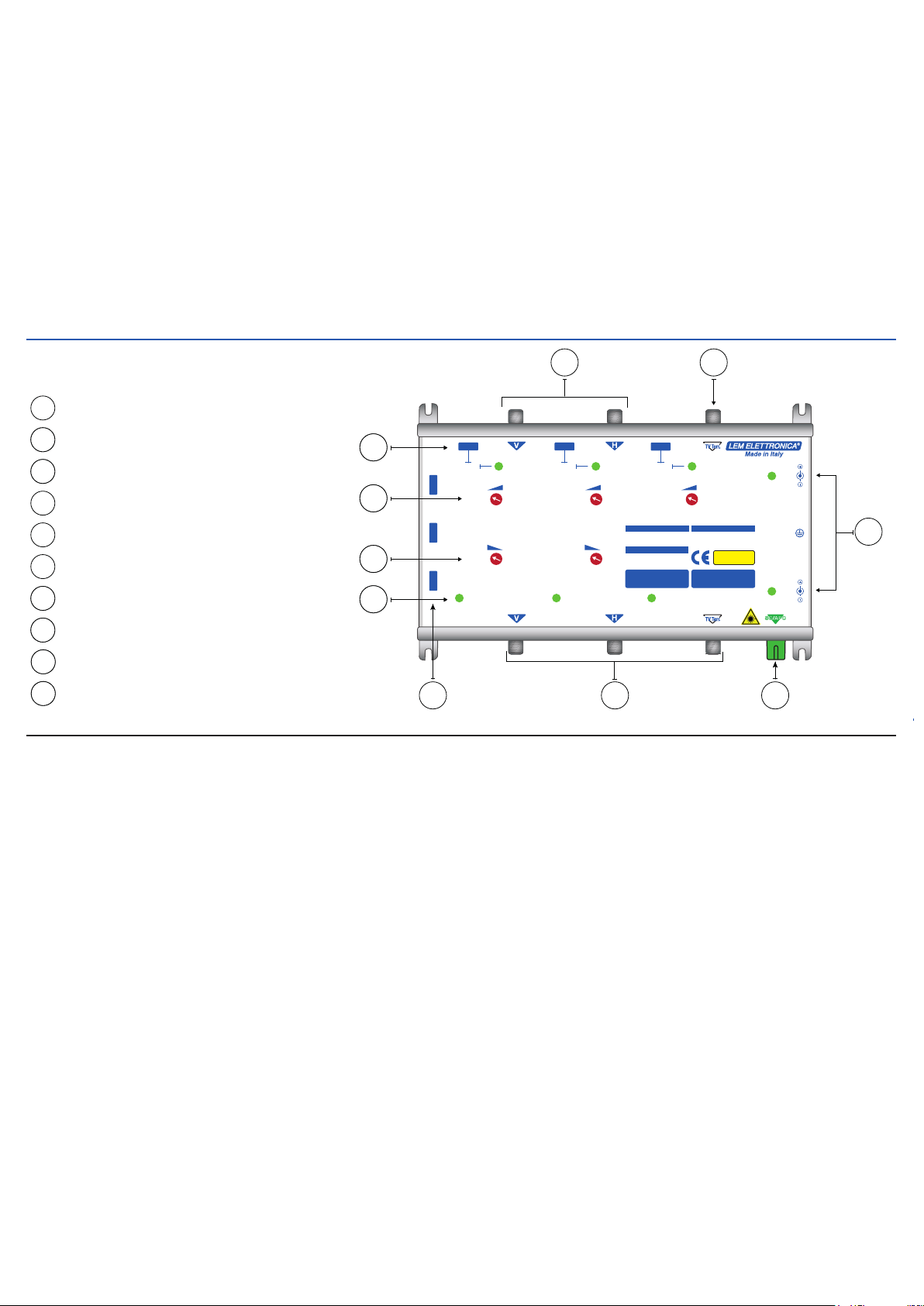
DESCRIPTION OF SYMBOLS AND ELECTRICAL SAFETY
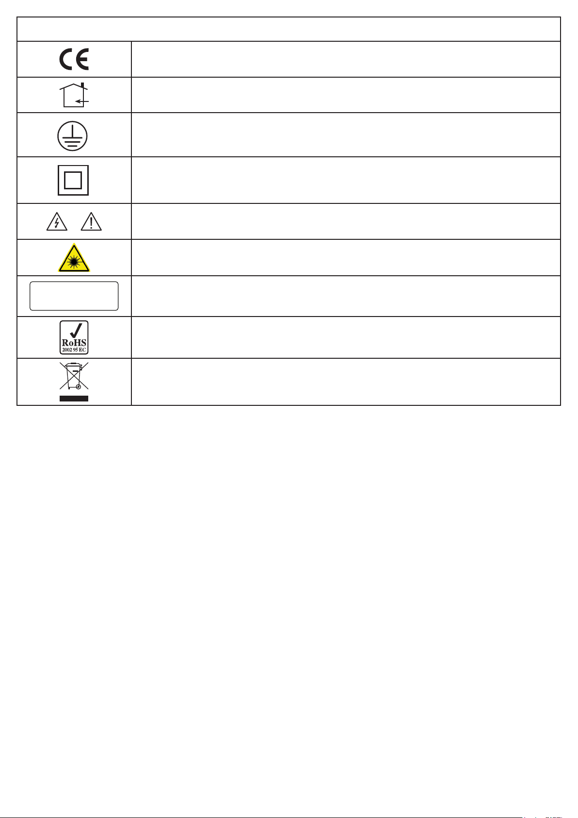
The equipment complies with the CE requirements
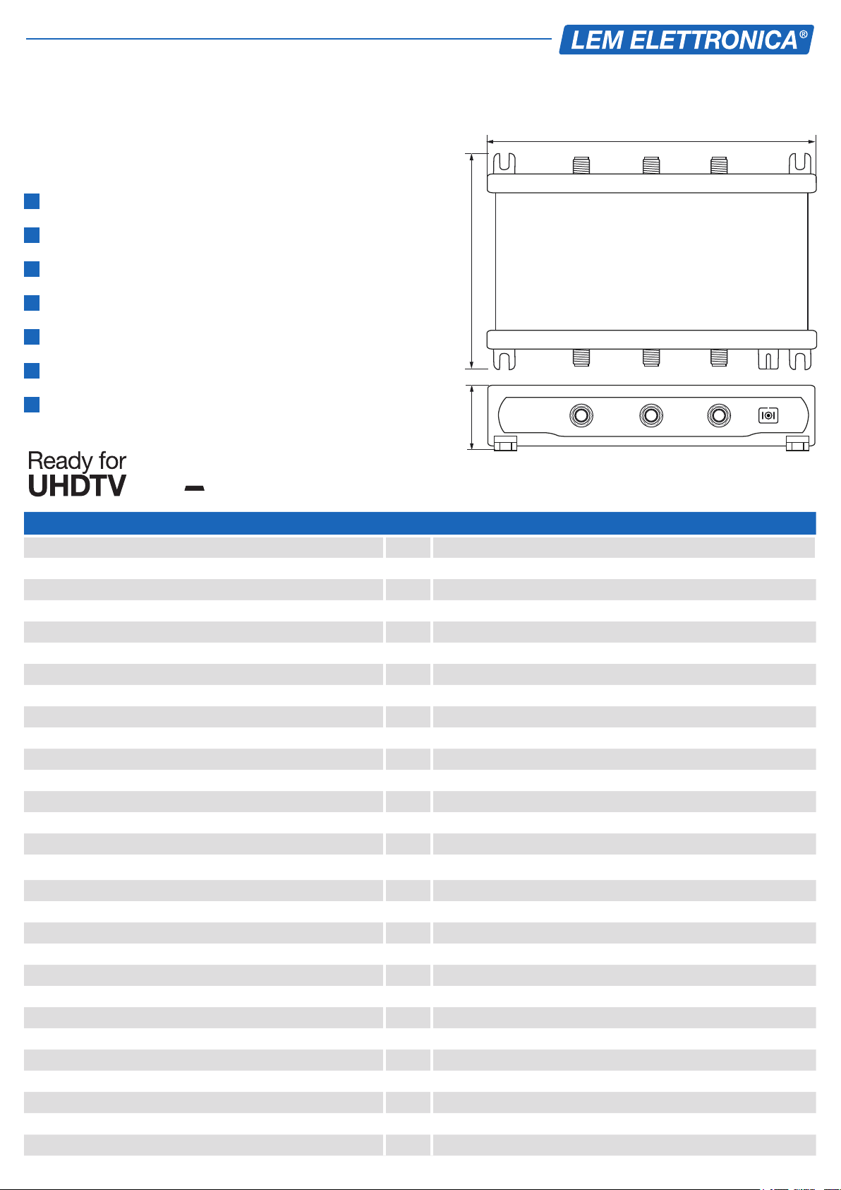
The equipment is designed for indoor use only
Equipment grounding terminal
This symbol indicates that the equipment complies with the class II equipment safety
requirements
CAUTION To avoid the risk of electric shock, do not open the equipment.
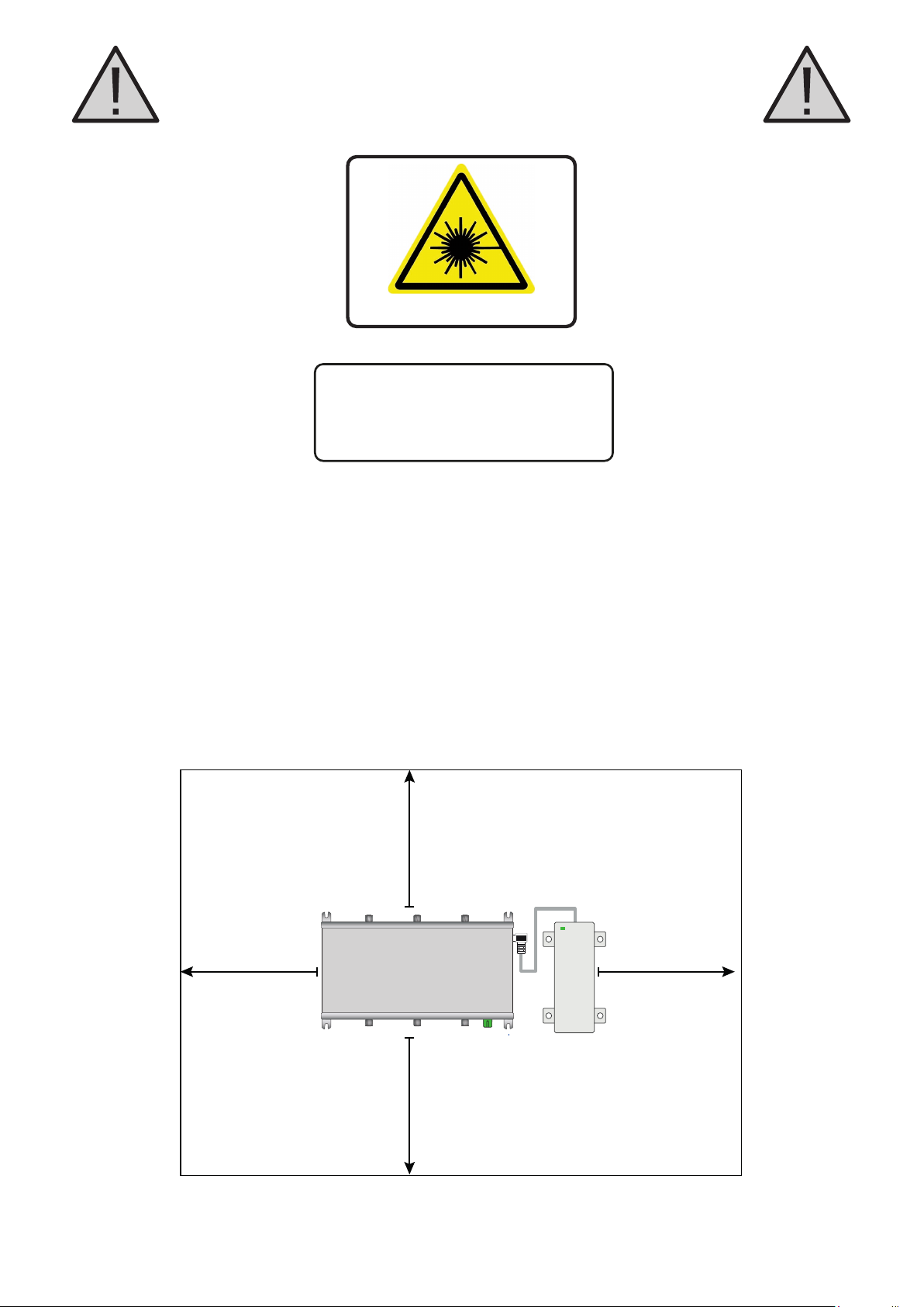
Invisible Laser Radiation avoid direct exposure to beam
INVISIBLE LASER RADIATION
DO NOT VIEW DIRECTLY WITH
OPTICAL INSTRUMENTS
CLASS 1M LASER PRODUCTS
Class 1M laser product. Do not watch directly with optical instruments
The equipment is compliant with RoHS 2011/65EU
Dispose according to local authorities recycling processes
1. Read carefully these instructions
2. Keep these instructions
3. Heed all warnings
4. Follow all instructions
5. Do not expose this apparatus to extreme temperatures
6. Do not install this apparatus near water or expose to rain and moisture
7. Place the apparatus in a dry and well-aired location
8. Install the unit on a vertical wall, or in a waterproof cabinet with a minimum IP55
rating, and fix it safely using the provided fixing plugs
9. Do not install the unit lying flat or on its top
10. Connect the power adapter cord to a detachable power supply socket
11. Unplug the apparatus during lighting storms or when unused for long time
12. Only use accessories specified by the manufacturer
13. Do not remove the cover without disconnecting from the mains first
14. Ambient temperature should not be lower than 0°C and higher than 50°C
15. Please allow air circulation around the apparatus
Safety instructions

20 cm 20 cm
20 cm
20 cm
PSU
Installation warnings
INVISIBLE LASER RADIATION
DO NOT VIEW DIRECTLY WITH
OPTICAL INSTRUMENTS
CLASS 1M LASER PRODUCTS
Laser Radiation
Place the apparatus and the power supplier in a dry and well-aired location
Install the unit on a vertical wall, or in a waterproof cabinet with a minimum IP55
rating, and fix it safely using the provided fixing plugs
Use only the power supplier provided with the amplifier.
The use of not-original power suppliers determines the not-compliance of the
product and can cause malfunctions and void the warranty

1
3
46 5
Wide Band LNB V - H inputs
1
Terrestrial Input (DTT, FM, DAB)
1
DC Inputs and power Leds
1
2
3
SC/APC Optical Output
4
Satellite V-H & TV Terr. Test/Monitor
5
Laser ON/OFF switches
6
17 Laser status Leds
Satellite V-H & TV Terr. level adjusters
18 Satellite V-H slope adjusters
19
Remote power feeding switches and Leds
110
2
DC POWER
9dB
DC INPUT
15... 20V
DC INPUT
15... 20V
Laser H Laser TV Terr.Laser V
OFF-ON
OFF-ONOFF-ON
Laser
T
Laser
H
Laser
V
OFF-ON
DC POWER
OFF-ON
DC POWER
OFF-ON
V Gain
V
Slope
9dB
H
Slope
15dB
H Gain
15dB
TV Gain
20dB
INVISIBLE LASER RADIATION
DO NOT VIEW DIRECTLY
CLASS M1 LASER PRODUCT
TXWBT
OPTICAL SATELLITE & TV
TRANSMITTER
Optical Wavelenghts: 1310 1330 1550nm
Output Level: >7dBm
Laser Class: 1M DIN EN 60825-1
Laser Type: un-cooled DBF
Input Freq. Range: 250... 2400MHz
Input Level Range: 65... 85dBµV
Input Return Loss: >12dB
Max. LNB Power: 300mA
SATELLITE INPUTS OPTICAL OUTPUT
Input Freq. Range: 80... 900MHz
Input Level with 32 MUX: 70dBµV
Return Loss: >12dB
Max. TV Terr. Power: 500mA
TV TERRESTRIAL INPUT
TEST
TEST TEST OUTPUT
DC LED MONITOR
Off...................................... DC Off
Green................................. DC On
Red............................ Short Circuit
LASER LED MONITOR
Off.................................... Laser Off
Green......................................... OK
Red............................ Laser Failure
88
89
810
87
TXWBT DESCRIPTION
LED MONITOR DESCRIPTION
DC Input Led
OFF= No power at the DC input
Green= DC Power
Laser Led
OFF= Laser switched OFF
Green= Laser switched ON
Red= Laser malfunction
Remote power Led
OFF= No power
Green= Remote power feeding active
Red= Short circuit
Box Content
01 TXWBT Optical transmitter
01 Power supplier unit (100-240Vac 0,5A Max / Output: 15Vdc 1,25A)
08 6x30mm xing plugs with 4,5x40mm screws
01 User manual

Tilt adjuster
1_Activate at least one V or H for LNB power feeding.
2_Connect a Satellite Signal Meter in spectrum mode to the TEST V port (Vertical polarization)
of the TXWBT transmitter. Rotate the VSlope adjuster until the spectrum appears at.
Satellite V e H Wide Band inputs adjustments.
Freq. (Mhz)
600300 900 1200 1500 1800 2100 2400
290 MHZ 2390 MHZ
Freq. (Mhz)
dB
600300 900 1200 1500 1800 2100 2400
290 MHZ 2390 MHZ
70
60
50
40
80
90
dB
70
60
50
40
80
90
Input pre-amplier gain adjustment
1_Select with the Satellite Signal Meter a transponder and operate on the VGain adjuster
to obtain a level comprised between 70 and 75 dBµV.
Freq. (Mhz)
600300 900 1200 1500 1800 2100 2400
290 MHZ 2390 MHZ
dB
70
60
50
40
80
90
Freq. (Mhz)
600300 900 1200 1500 1800 2100 2400
290 MHZ 2390 MHZ
dB
70
60
50
40
80
90
Because of possible dierent levels of propagation due to weather conditions the TXWBT
Wide Band inputs are equipped with automatic Gain Control circuits. For perfect signal
loss compensation and negative slope equalization of the coaxial cable between the LNB
WideBand and the transmitter inputs no additional devices are required. The TXWBT
Satellite V and H inputs have built-in pre-ampliers and tilt adjusters.
To set-up the H horizontal Wide Band input connect the Satellite Signal Meter to H
Test port and repeat step by step the same procedure applied for the input.
For optimal working range of the A.C.G. circuits please set-up the slope and signal
level of each input rst.

Terrestrial optimal TV Terrestrial level set-up
1_Connect a Satellite Signal Meter to the TV Terrestrial Test point connector
2_Set the TV Gain adjuster of the TXWBT transmitter to obtain the values showed below
at the TV Terrestrial Test output.
Freq. (Mhz)
0 900
175 MHZ 790 MHZ
dBµV
70
60
50
40
80
90
dBµV
70
60
50
40
80
90
Freq. (Mhz)
0 900
175 MHZ 790 MHZ
77dBµV
The FM and DAB signal levels should be at least 10dB lower than the DTT signals
Example (A): Scenario with 8 digital TV terrestrial channels plus DAB and FM in a PON
(Passive Optical Network) of 16 optical points. The optimal signal level at the TV Terr. Test
output should be 77dBµV. This level can be set adjusting the TV Terr. Gain trimmer.
These levels are guidelines in an ideal scenario, assuming that all DTT signal channels
at the input are steady and at the same level, if not, the use of a DTT signal equalizer
like the DSP20 is highly recommended.
Example (B): Scenario with 16 digital TV terrestrial channels plus DAB and FM in a PON
(Passive Optical Network) of 32 optical points. The optimal signal level at the TV Terr. Test
output should be 74dBµV, this level can be set adjusting the TV Terr. Gain trimmer.
Freq. (Mhz)
0 900
175 MHZ 790 MHZ
Freq. (Mhz)
0 900
175 MHZ 790 MHZ
dBµV
70
60
50
40
80
90
dBµV
70
60
50
40
80
90
74dBµV
RF Level at TV Gain test output
TV Channels -7dB Optical -10dB Optical -14dB Optical -17dB Optical -21dB Optical
40 60dBµV 65dBµV 70dBµV 70dBµV 70dBµV
16 64dBµV 69dBµV 74dBµV 74dBµV 74dBµV
867dBµV 72dBµV 77dBµV 77dBµV 77dBµV
470dBµV 75dBµV 80dBµV 80dBµV 80dBµV
173dBµV 79dBµV 83dBµV 83dBµV 83dBµV

PSUPSU
PSU PSU
PSU
V H
LNB
WIDE
BAND
PSU
TV Terr.
Radio
SAT/dCSS/Legacy
Test SAT V
TXWBT
DSP20
Test SAT H
Test TV Terr.
Optical Splitter 1x32 Optical Splitter 1x32
Optical
Splitter
SCF316/4 SCF316/8 SCF316/6
SCF316/2
Single-Mode
Fibre Optic
9/125
DC
Powering
Line
The TXWBT headend converts and transmits over a single-mode optical fibre the terrestrial
signals (DTT, FM, DAB) processed by the programmable terrestrial headend DSP20 and
all the transponders of a satellite received from a Wide Band LNB. The optical signals are
received by the optical multiswitch of the SCF316 series and converted into RF ready for a
single or multi-dwelling coaxial distribution. Each SCF316 series output provides terrestrial
and satellite signals supporting the legacy or SCR/dCSS standards (AUTO-SWITCH).

LEM ELETTRONICA srl •Via Grezze, 38 •25015 Desenzano d/G •Italy
Tel. +39 0309120006 • Fax. +39 0309123035 • info@lemelettronica.it
www.lemelettronica.it
Label with serial and tracking data
Model Serial # Manuf.
Week
Manuf.
Year
HW
Rel.
FW
Rel.
Table of contents
Popular Transmitter manuals by other brands

Simplified MFG
Simplified MFG TX1PRO user manual

COBHAM
COBHAM T-2765-KF quick start

Emerson
Emerson Micro Motion 1700 Configuration and Use Manual

Honeywell
Honeywell 5816 Installation and setup guide

RKI Instruments
RKI Instruments 65-2330RK Operator's manual

Lectrosonics
Lectrosonics IFBT4-VHF/X instruction manual