PCI Express GRL-PCIE-TX Setup guide

GRL-PCIE-TX PCI Express®5.0 Transmitter Compliance Test
Automation Solution
Quick Start/User Guide/Method of Implementation (MOI)
for PCIe Gen5 Physical Layer Transmitter Test Application
Published on 26 March 2022

GRL-PCIE-TX Quick Start/User Guide/MOI Rev1.0
© PCI-SIG 2022
Version 1.0, Mar 2022. Updated 03.26.2022 Page.2
DISCLAIMER
This document is provided "as is" with no warranties whatsoever, including any warranty of
merchantability, no infringement, fitness for any particular purpose, or any warranty otherwise
arising out of any proposal, specification, or sample. The PCI-SIG disclaims all liability for
infringement of proprietary rights, relating to use of information in this specification. No license,
express or implied, by estoppel or otherwise, to any intellectual property rights is granted herein.
All product names are trademarks, registered trademarks, or service marks of their respective
owners.
Copyright © 2022 PCI-SIG. All rights reserved.

GRL-PCIE-TX Quick Start/User Guide/MOI Rev1.0
© PCI-SIG 2022
Version 1.0, Mar 2022. Updated 03.26.2022 Page.3
TABLE OF CONTENTS
TABLE OF CONTENTS 3
1INTRODUCTION 5
2RESOURCE REQUIREMENTS 6
2.1 EQUIPMENT REQUIREMENTS .................................................................................................... 6
2.2 SOFTWARE REQUIREMENTS...................................................................................................... 7
3SETTING UP GRL-PCIE-TX AUTOMATION SOFTWARE 8
3.1 DOWNLOAD GRL-PCIE-TX SOFTWARE...................................................................................... 8
3.2 LAUNCH AND SET UP GRL-PCIE-TX SOFTWARE ......................................................................... 8
3.3 PRE-CONFIGURE GRL-PCIE-TX SOFTWARE BEFORE TESTING..................................................... 11
3.3.1 Enter Test Session Information ............................................................................... 11
3.3.2 Set Test Conditions .................................................................................................. 11
4TESTING USING GRL-PCIE-TX 14
4.1 GRL-PCIE-TX ADVANTAGE.................................................................................................... 14
4.2 SET UP DUT TX TEST WITH AUTOMATION................................................................................ 14
4.2.1 Connect Equipment for System Board DUT Test.................................................... 15
4.2.2 Connect Equipment for Add-In Card DUT Test ....................................................... 16
4.2.3 Connect Equipment for System Ref Clock Jitter Test ............................................ 19
4.2.4 Set Up Test Requirements ....................................................................................... 20
4.2.5 Select Compliance Tests.......................................................................................... 22
4.2.6 Configure Test Parameters...................................................................................... 25
4.3 RUN AUTOMATION TESTS ...................................................................................................... 27
5INTERPRETING GRL-PCIE-TX TEST REPORT 28
5.1 UNDERSTAND TEST REPORT INFORMATION............................................................................... 28
5.1.1 Test Session Information......................................................................................... 28
5.1.2 Test Summary Table ................................................................................................ 29
5.1.3 Test Results .............................................................................................................. 29
5.2 DELETE TEST RESULTS .......................................................................................................... 32
6SAVING AND LOADING GRL-PCIE-TX TEST SESSIONS 33
7APPENDIX A: METHOD OF IMPLEMENTATION (MOI) FOR MANUAL PCIE 5.0
TRANSMITTER MEASUREMENTS 34
7.1 SYSTEM BOARD TX SIGNAL QUALITY TEST ................................................................................ 34
7.2 ADD-IN CARD TX SIGNAL QUALITY TEST ................................................................................... 37

GRL-PCIE-TX Quick Start/User Guide/MOI Rev1.0
© PCI-SIG 2022
Version 1.0, Mar 2022. Updated 03.26.2022 Page.4
7.3 SYSTEM BOARD TX PRESET TEST ............................................................................................ 39
7.4 ADD-IN CARD TX PRESET TEST............................................................................................... 39
7.5 SYSTEM BOARD TX BASE JITTER (UPW-TJ, UPW-DJDD, UTJ AND UDJDD) TEST ....................... 41
7.6 ADD-IN CARD TX BASE JITTER (UPW-TJ, UPW-DJDD, UTJ AND UDJDD) TEST.......................... 42
7.7 SYSTEM BOARD REF CLOCK (100 MHZ) JITTER TEST................................................................. 44
8APPENDIX B: CONNECTING KEYSIGHT OSCILLOSCOPE TO PC 45
9APPENDIX C: CONNECTING TEKTRONIX OSCILLOSCOPE TO PC 46

GRL-PCIE-TX Quick Start/User Guide/MOI Rev1.0
© PCI-SIG 2022
Version 1.0, Mar 2022. Updated 03.26.2022 Page.5
1Introduction
This Quick Start/User Guide/MOI provides information using the GRL-PCIE-TX test solution to set
up and test an electrical transmitter (Tx) device for PCI Express (PCI-SIG SEG) certification.
The main body of this documentation describes how to configure the GRL-PCIE-TX solution to
capture and test waveforms in a PCIe 5.0 system (lane, data rate, preset), or individual waveforms,
and perform SigTest signal quality and de-emphasis compliance tests. The test automation is
carried out based on PCI-SIG-approved Methods of Implementation (MOI’s) with high
performance real-time oscilloscopes using existing PCI-SIG Compliance Base Boards (CBB’s) and
Compliance Load Boards (CLB’s).
The GRL-PCIE-TX solution consists of the GRL PCIe “GRL-P1” hardware controller and automation
software (GRL-PCIE-TX). The GRL-PCIE-TX software when run from the computer or oscilloscope
enables automation control to test the device under test (DUT) for Tx electrical compliance. The
GRL-P1 hardware controller is designed to work primarily with the software to provide
compliance toggle to control the state of the DUT. Alternatively, an arbitrary function generator
can also be used as a secondary option for compliance toggle control. The GRL test solution also
extends support for RF switch integration to automate switching or selection of the lane under
test.
The GRL automation control enabled PC or scope automates power and signal quality test
sequencing and processing of captured waveforms for the DUT at the selected PCIe data rate. The
Tx path is tested with worst case eye to ensure a Bit Error Ratio (BER) of less than 1E-12 can be
achieved. When combined with a satisfactory level of interoperability testing, these tests provide
a reasonable level of confidence that the DUT’s will function properly in most PCIe environments.
This documentation covers the following major components for PCIe Tx testing.
1. GRL-P1 hardware controller setup.
2. GRL-PCIE-TX software configuration and test setup.
Note: For manual test methodology, please refer to PCI-SIG SEG for approved vendor specific Method
of Implementation (MOI’s) as technical reference.

GRL-PCIE-TX Quick Start/User Guide/MOI Rev1.0
© PCI-SIG 2022
Version 1.0, Mar 2022. Updated 03.26.2022 Page.6
2Resource Requirements
Note: Equipment requirements may vary according to the lab setup and DUT board. Below are the
recommended lists of equipment for the typical test setup.
2.1 Equipment Requirements
TABLE 1. EQUIPMENT REQUIREMENTS –SYSTEMS
Equipment
Qty.
Description/Key Spec Requirement
High Performance Real-time Oscilloscope [a]
1
≥33 GHz bandwidth (For PCIe Gen5)
Sample rate: ≥ 128 Gb/s with 2x interpolation
“GRL-P1” PCIe Compliance Test Hardware
Controller (Optional)
1
For PCIe compliance toggle control
Advanced Technology eXtended (ATX) Power
Supply
1
For power supply to the DUT
GRL Switch (Optional)
1
For multi-lane automated testing
PCI-SIG Compliance Base Board (CBB)
or
PCI-SIG Compliance Load Board (CLB)
1
For add-in cards
For hosts
Computer (laptop or desktop)
1
Windows 7+ OS
For automation control of the DUT state
[a] Oscilloscope with scope software requirements as specified in vendor specific MOI’s. For example, when
using the Keysight Scope, scope software such as Keysight InfiniiSim / EZ-JIT / Serial Data Analysis / Serial
Data Equalization that are required for testing and signal processing must be pre-installed on the Scope.
Similarly, the Tektronix Scope shall be used with DPOJET (Jitter and Eye Analysis Tools) software for making
measurements.
TABLE 2. EQUIPMENT REQUIREMENTS –CABLES
Cable
Qty.
Power Control Adapter Cable
1
USB Type-A to Type-A/B Micro Cable
1
Test Fixture Control Cable (2-conductor power control only cable or
6-conductor fixture control cable)
1
Clock Compliance Toggle Cables (matched SMA-to-SMP cables)
1 pair
SMA-to-SMP Cables
4 pairs[a]
[a] Based on the standard test configuration. May require more or less cables depending on the DUT
type.

GRL-PCIE-TX Quick Start/User Guide/MOI Rev1.0
© PCI-SIG 2022
Version 1.0, Mar 2022. Updated 03.26.2022 Page.7
2.2 Software Requirements
TABLE 3. SOFTWARE REQUIREMENTS
Software
Description/Source
GRL-PCIE-TX
Granite River Labs PCI Express®5.0 Automated Transmitter Compliance Test
Solution (hardware & software) –www.graniteriverlabs.com
Further automation license for Custom DUT, RF Switch, or other bench
automation –www.graniteriverlabs.com
VISA (Virtual Instrument
Software Architecture)
API Software
VISA Software is required to be installed on the controller PC running GRL-
GRL-PCIE-TX software. GRL’s software framework has been tested to work
with all three versions of VISA available on the Market:
1. NI-VISA: http://www.ni.com/download/ni-visa-17.0/6646/en/
2. Keysight IO Libraries: www.keysight.com (Search on IO Libraries)
3. Tektronix TekVISA: www.tek.com (Downloads > Software > TekVisa)
SigTest
Standard Post Processing Analysis Software –
www.intel.com/content/www/us/en/design/technology/high-speed-
io/tools.html

GRL-PCIE-TX Quick Start/User Guide/MOI Rev1.0
© PCI-SIG 2022
Version 1.0, Mar 2022. Updated 03.26.2022 Page.8
3Setting Up GRL-PCIE-TX Automation Software
This section provides the procedures to start up and pre-configure the GRL-PCIE-TX automation
software before running tests. It also helps users familiarize themselves with the basic operation
of the software.
Note: The GRL-PCIE-TX software installer will automatically create shortcuts in the Desktop and
Start Menu when installing the software.
To start using the GRL-PCIE-TX software, follow the procedures in the following sections.
3.1 Download GRL-PCIE-TX Software
Download and install the GRL-PCIE-TX software as follows:
1. If the GRL-PCIE-TX software is to be installed on a PC (where is referred to as ‘controller PC’),
install VISA (Virtual Instrument Software Architecture) on to the PC where the GRL software is
to be used (see Section 2.2).
2. Download the software ZIP file package from the Granite River Labs support site.
3. The ZIP file contains:
•PCIETxTestApplicationxxxxxxxxxxxxSetup.exe –Run this on the PC or on the
oscilloscope to install the GRL-PCIE-TX application.
•PCIe4_TxTestScopeSetupFilesInstallationxxxxxxxxxSetup.exe –Run this on the
oscilloscope to install the scope setup files.
3.2 Launch and Set Up GRL-PCIE-TX Software
4. Once the GRL-PCIE-TX software is installed, open the GRL folder from the Windows Start
menu. Click on GRL –Automated Test Solutions within the GRL folder to launch the GRL
software framework.
FIGURE 1. SELECT AND LAUNCH GRL FRAMEWORK

GRL-PCIE-TX Quick Start/User Guide/MOI Rev1.0
© PCI-SIG 2022
Version 1.0, Mar 2022. Updated 03.26.2022 Page.9
5. From the Application→Framework Test Solution drop-down menu, select “PCIE Tx Test
Application” to start the PCIe Tx Test Application. If the selection is grayed out, it means that
your license has expired.
FIGURE 2. START PCIE TX TEST APPLICATION
6. To enable license, go to License→License Details.
FIGURE 3. SEE LICENSE DETAILS
a) Check the license status for the installed application.
FIGURE 4. CHECK LICENSE FOR INSTALLED APPLICATIONS
b) Activate a License:
•If you have an Activation Key, enter it in the field provided and select “Activate”.
•If you do not have an Activation Key, select “Close” to use a demo version of the software
over a free 10-day trial period.

GRL-PCIE-TX Quick Start/User Guide/MOI Rev1.0
© PCI-SIG 2022
Version 1.0, Mar 2022. Updated 03.26.2022 Page.10
Note: Once the 10-day trial period ends, you will need to request an Activation Key to continue using
the software on the same computer or oscilloscope. The demo software is also limited in its
capability, in that it will only calibrate the maximum frequency for each data rate. Thus, the demo
version cannot be used to fully calibrate and test a device. For Demo and Beta Customer License
7. Select the Equipment Setup icon on the PCIe Tx Test Application menu.
8. Connect the oscilloscope with the controller PC through either GPIB, USB or LAN. (Note:
Additional information for connecting the Keysight and Tektronix oscilloscopes to the controller
PC is provided in the Appendix of this document.)
9. If using an RF Switch, connect the switch via GPIB to the GRL automation control enabled
Scope or PC.
10. If using an Arbitrary Function Generator (AFG) as the compliance toggle control, connect the
AFG via USB to the GRL automation control enabled Scope or PC.
11. On the Scope or PC, obtain the network addresses for all the connected instruments from the
device settings. These addresses will be used to connect the instruments to the GRL
automation software.
12. If using the GRL-P1 hardware controller, connect the controller via USB to the GRL automation
control enabled Scope or PC.
13. On the Scope or PC, obtain the network address for the connected GRL-P1 from the device
settings. For example, if GRL-P1 is connected to the PC, open the Device Manager which
should detect the controller as a Controller Serial (COM) Port, e.g. “GRL PCIe34 P1 (COM10)”.
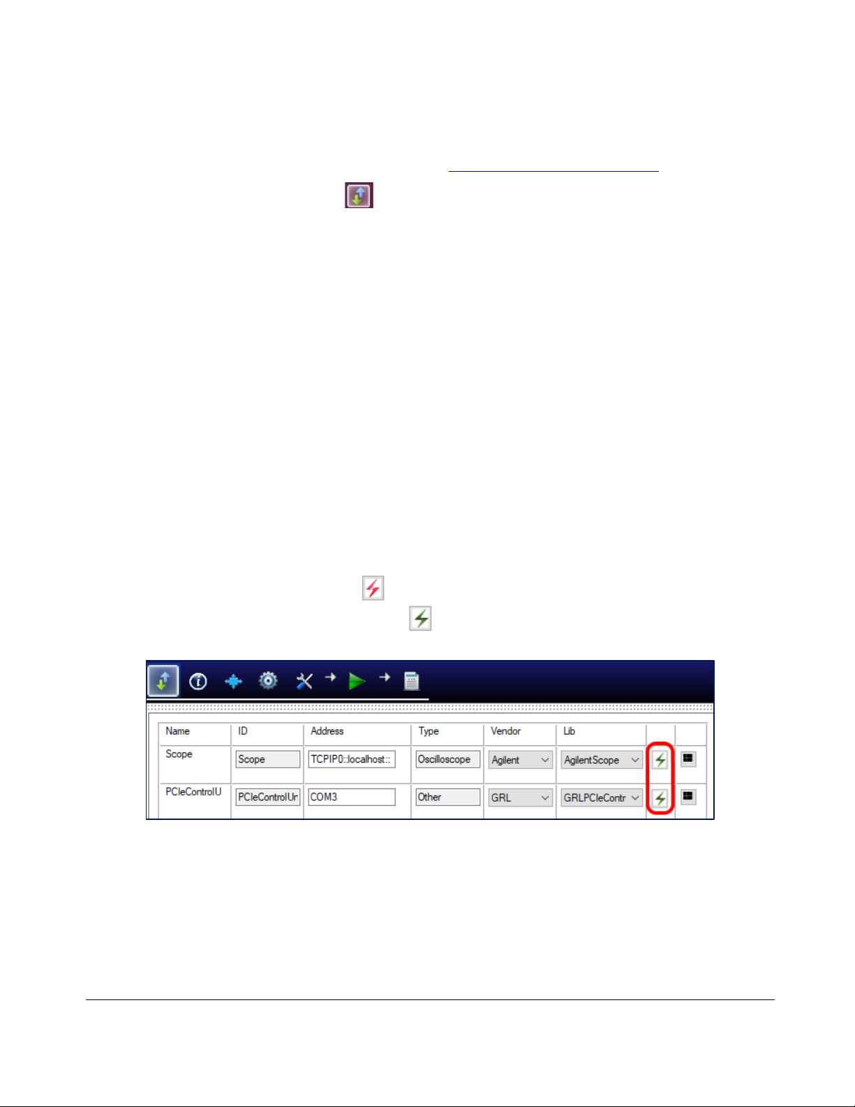
14. On the Equipment Setup page of the GRL PCIe Tx Test Application, type in the address of each
connected instrument into the “Address” field.
Then select the “lightning” button ( ) for each connected instrument.
The “lightning” button should turn green ( ) once the application has successfully
established connection with each instrument.
FIGURE 5. CONNECT INSTRUMENTS WITH GRL-PCIE-TXSOFTWARE
13. (Note: If the GRL-PCIE-TX software is installed on the Tektronix Scope, ensure the Scope is
connected via GPIB and type in the GPIB network address, for example “GPIB8::1::INSTR.) If the
GRL software is installed on the PC to control the Scope, type in the Scope IP address, for
example “TCPIP0::192.168.0.110::inst0::INSTR”. Note to omit the Port number from the
address. The “lightning” button should turn green if successfully connected to the instrument.

GRL-PCIE-TX Quick Start/User Guide/MOI Rev1.0
© PCI-SIG 2022
Version 1.0, Mar 2022. Updated 03.26.2022 Page.11
3.3 Pre-Configure GRL-PCIE-TX Software Before Testing
Once all equipment is successfully connected from the previous section, proceed to set up the
preliminary settings before going to the advanced test setup.
3.3.1 Enter Test Session Information
Select from the menu to access the Session Info page. Enter the information as required for
the test session that is currently being run. The information provided will be included in the test
report generated by the software once tests are completed.
•The fields under DUT Info and Test Info are defined by the user.
•The Software Info field is automatically populated by the software.
FIGURE 6. SESSION INFO PAGE
3.3.2 Set Test Conditions
Select from the menu to access the Conditions page to set the conditions for testing. The
software will run tests for the PCIe data lanes, data rates, and preset settings that are selected.
a) Lane tab: Select the desired data lanes to be tested.

GRL-PCIE-TX Quick Start/User Guide/MOI Rev1.0
© PCI-SIG 2022
Version 1.0, Mar 2022. Updated 03.26.2022 Page.12
FIGURE 7. SELECT LANE UNDER TEST
b) Data Rate tab: Select the desired PCIe data rates for testing.
FIGURE 8. SELECT DATA RATES
c) Preset tab: Select the pre-defined Tx presets as required for Tx equalization.

GRL-PCIE-TX Quick Start/User Guide/MOI Rev1.0
© PCI-SIG 2022
Version 1.0, Mar 2022. Updated 03.26.2022 Page.13
FIGURE 9. SELECT PRESETS

GRL-PCIE-TX Quick Start/User Guide/MOI Rev1.0
© PCI-SIG 2022
Version 1.0, Mar 2022. Updated 03.26.2022 Page.14
4Testing Using GRL-PCIE-TX
The GRL-PCIE-TX test solution supports automated Tx compliance testing using the SigTest signal
quality/de-emphasis and stress tolerance analysis application for PCIe system board and add-in
card DUT’s. In a typical test environment, the GRL-PCIE-TX automation software is run from the
PC/oscilloscope and communicates with the GRL-P1 hardware controller. This enables
automation control for the DUT’s power and signal quality test sequence, as well as waveform
acquisition for PCIe Gen5. Optionally an arbitrary function generator can also be used as an
alternative compliance toggle controller.
The GRL-P1 controller can be connected to either a PCI-SIG compliance load board (CLB) test
fixture for the system board DUT or compliance base board (CBB) test fixture for the add-in card
DUT. The GRL automation control enabled PC/Scope will send commands to GRL-P1 which
controls the power to the DUT and provides a compliance toggle signal to cause the DUT to enter
the next compliance state.
The DUT will transmit the test signal to the oscilloscope that is used to validate the test pattern of
the signal. The compliance signal will be captured and saved as a waveform file which is then
measured for stress tolerance and preset test compliance. In between, an optional RF switch can
be used and controlled by the GRL-PCIE-TX software to automate selection of the lane under test.
When testing is completed, the software will generate a test report detailing all results from all
lanes tested.
4.1 GRL-PCIE-TX Advantage
The GRL-PCIE-TX test solution provides a more efficient way to perform PCIe Tx compliance
testing rather than using traditional manually-driven methods that are generally both time-
consuming and error prone, tying up valuable equipment and resources.
To increase test efficiency, the GRL-P1 controller will first quickly capture waveforms on the
oscilloscope. Then using a separate computer, the GRL-PCIE-TX software will run PCIe compliance
tests for the waveforms, SigTest signal quality, and de-emphasis.
Through this offline processing of captured waveforms, the oscilloscope can be freed up for other
work. The test time can also be further reduced with the software’s multi-threading of SigTest.
Another advantage is that GRL-P1 can be programmed to automatically capture only the
waveforms for the test that the user wants to perform.
4.2 Set Up DUT Tx Test with Automation
Once pre-configuration has been completed from Section 3.3, continue with the test setup. The
following procedures show how to set up the test environment to perform automated Tx
compliance testing for both the System Board and Add-In Card DUT’s.

GRL-PCIE-TX Quick Start/User Guide/MOI Rev1.0
© PCI-SIG 2022
Version 1.0, Mar 2022. Updated 03.26.2022 Page.15
4.2.1 Connect Equipment for System Board DUT Test
The connection diagrams below show the recommended equipment setups to perform waveform
acquisition and analysis for the PCIe System Board DUT using a GRL automation control enabled
Scope and test controller method.
4.2.1.1 Setup Using GRL-P1 Hardware Controller with PCIe Test Fixtures
The following diagrams describe how to connect the equipment if using GRL-P1 with the PCIe
Gen5 Compliance Load Board (CLB). Note the use of GRL-P1 in the setup is optional.
4.2.1.1.1 PCIe Gen5 System Board Connection Setup
FIGURE 10.CONCEPTUAL PCIE GEN5SYSTEM BOARD TX TEST SETUP DIAGRAM USING GRL-P1
1. Insert the CLB into the designated slot on the DUT.
2. Connect the Tx+ Data Lane from the CLB to Channel 1 of the Scope.
3. Connect the Tx- Data Lane from the CLB to Channel 3 of the Scope.
4. Connect the CLB Rx+ Lane to the GRL-P1 Output 1.
5. Connect the CLB Rx- Lane to the GRL-P1 Output 2.
6. Connect the power control adapter cable from the ATX power supply to the DUT.

GRL-PCIE-TX Quick Start/User Guide/MOI Rev1.0
© PCI-SIG 2022
Version 1.0, Mar 2022. Updated 03.26.2022 Page.16
7. Connect the GRL-P1’s power control only cable to the input of the power control adapter
cable.
8. Connect GRL-P1 to the Scope using a USB cable.
9. If using ISI, connect a 2.3 dB ISI in between the CLB Tx outputs and Scope channels (Figure 11
below).
FIGURE 11.CONCEPTUAL PCIE GEN5SYSTEM BOARD TX TEST SETUP DIAGRAM USING GRL-P1 (WITH ISI)
4.2.2 Connect Equipment for Add-In Card DUT Test
The following connection diagrams show the recommended equipment setups to perform
waveform acquisition and analysis for the PCIe Add-In Card DUT using a GRL automation control
enabled Scope and test controller method.
4.2.2.1 Setup Using GRL-P1 Hardware Controller with PCIe Test Fixtures
The following diagrams describe how to connect the equipment if using GRL-P1 with the PCIe
Gen5 Compliance Base Board (CBB). Note the use of GRL-P1 in the setup is optional.

GRL-PCIE-TX Quick Start/User Guide/MOI Rev1.0
© PCI-SIG 2022
Version 1.0, Mar 2022. Updated 03.26.2022 Page.17
4.2.2.1.1 PCIe Gen5 Add-In Card Connection Setup
Note: The use of GRL-P1 in the setup is optional.
FIGURE 12.CONCEPTUAL PCIE GEN5ADD-IN CARD TX TEST SETUP DIAGRAM USING GRL-P1
1. Attach the DUT to the designated slot on the CBB.
2. Connect the Tx+ Data Lane from the CBB to Channel 1 of the Scope.
3. Connect the Tx- Data Lane from the CBB to Channel 3 of the Scope.
4. Connect the Rx+ Lane from the CBB to the GRL-P1 Output 1.
5. Connect the Rx- Lane from the CBB to the GRL-P1 Output 2.
6. Connect the power control adapter cable from the ATX power supply to the CBB.
7. Connect the GRL-P1’s power control only cable to the input of the power control adapter
cable.
8. Connect GRL-P1 to the Scope using a USB cable.
9. If using ISI, connect a 12.5 dB ISI in between the CBB Tx outputs and Scope channels (Figure 13
below).

GRL-PCIE-TX Quick Start/User Guide/MOI Rev1.0
© PCI-SIG 2022
Version 1.0, Mar 2022. Updated 03.26.2022 Page.18
FIGURE 13.CONCEPTUAL PCIE GEN5ADD-IN CARD TX TEST SETUP DIAGRAM USING GRL-P1 (WITH ISI)

GRL-PCIE-TX Quick Start/User Guide/MOI Rev1.0
© PCI-SIG 2022
Version 1.0, Mar 2022. Updated 03.26.2022 Page.19
4.2.3 Connect Equipment for System Ref Clock Jitter Test
The following connection diagram shows the recommended equipment setup to perform
waveform acquisition and analysis for the PCIe Gen5 System Ref Clock Jitter Test.
FIGURE 14.CONCEPTUAL PCIE GEN5SYSTEM REF CLOCK JITTER TEST SETUP DIAGRAM
1. Insert the CLB into the designated slot on the DUT.
2. Connect Ref Clk+ from the CLB to Channel 1 of the Scope.
3. Connect Ref Clk- from the CLB to Channel 3 of the Scope.
1. Connect the power control adapter cable from the ATX power supply to the DUT.

GRL-PCIE-TX Quick Start/User Guide/MOI Rev1.0
© PCI-SIG 2022
Version 1.0, Mar 2022. Updated 03.26.2022 Page.20
4.2.4 Set Up Test Requirements
After setting up the physical equipment, select from the GRL PCIe Tx Test Application menu to
access the Setup Configuration page. Select the DUT to be tested, set up and run SigTest, and set
up waveform processing to be applied for testing.
a) Device Type tab: Select to use either a PCIe System Board or Add-In Card as the DUT.
Select to use either the PCIe CEM, PCIe Gen3 U.2 (SFF-8639) or PCIe Gen3 M.2 fixture
connector as supported by the DUT.
FIGURE 15.SELECT DUT TYPE
FIGURE 16.SELECT DUT FIXTURE CONNECTOR TYPE
b) SigTest Settings tab:
•PCIE Gen1 (2.5Gb/s), Gen2 (5Gb/s) and Gen3 (8Gb/s) ‒Select to run either the pre-defined
Version “3.2.0.3” or a “Custom”Version of the SigTest. If “Custom” is selected, enter the
Version number of the Custom SigTest and also make sure that the SigTest is already
installed in the system.
•PCIE Gen4 (16Gb/s) ‒Enter the SigTest Version for running Signal Quality (SQ) or Preset
Tests and also make sure that the SigTest is already installed in the system.
•PCIE Gen5 (32Gb/s) ‒Enter the SigTest Version for running Signal Quality (SQ) or Preset
Tests and also make sure that the SigTest is already installed in the system.
Table of contents