LEM L100-RX User manual


IMPORTANT SAFETY INSTRUCTIONS
INSTRUCTIONS PERTAINING TO A RISK OF FIRE, ELECTRIC SHOCK OR INJURY TO PERSONS
WARNING - When using electric products, basic precautions should always be followed, including the
following:
1. Read all the SAFETY INSTRUCTIONS before using the product.
2. To reduce the risk of injury, close supervision is necessary when the product is used near children.
3. Do not use this product near water - for example, near a bathtub, washbowl, kitchen sink, in a wet
basement or near a swimming poor or the like.
4. This product in combination with headphones or an amplifier, may be capable of producing sound
levels that could cause permanent hearing loss. Do not operate for a long period of time at high volume
level or at a level that is uncomfortable. If you experience any hearing loss or ringing in the ears, you
should consult an audiologist.
5. This product should be located so that its location or position does not interfere with its proper
ventilation.
6. This product should be located away from heat sources such as radiators, heat registers or other
products that produce heat.
7. The product should be connected to a power supply only of the type described on the operating
instructions or as marked on the product.
8. This product may be equipped with a polarized line plug (one blade wider than the other). This is a
safety feature. If you are unable to insert the plug into the outlet, contact an electrician to replace your
obsolete outlet. Do not defeat the safety purpose of the plug.
9. The power-supply cord of the product should be unplugged from the outlet when left unused for a
long period of time. When unplugging the power-supply cord, do not pull on the cord, but grasp it by
the plug.
10. Care should be taken so that object do not fall and liquid are not spilled into the enclosure through
openings.
11. The product should be serviced by qualified service personnel when:
A. The power-supply cord or the plug has been damaged; or
B. Objects have fallen, or liquid has been spilled into the product; or
C. The product has been exposed to rain; or
D. The product does not appear to operate normally or exhibits a marked change in performance; or
E. The product has been dropped or the enclosure damaged.
12. Do not attempt to service the product beyond that described in the user-maintenance instructions.
All other servicing should be referred to qualified service personnel.
13. WARNING - Do not place objects on the product's power cord or place it in a position where anyone
could trip over, walk on or roll anything over it. Do not allow the product to rest on or to be installed over
power cords of any type. Improper installations of this type create the possibility of fire hazard and/or
personal injury.
SAVE THESE INSTRUCTIONS
The lightning flash with arrowhead symbol within an
equilateral triangle is intended to alert the user to the
presence of uninsulated "dangerous voltage" within the
product's enclosure, that may be of sufficient magnitude to
constitute a risk of electric shock to persons.
The exclamation point within an equilateral triangle is
intended to alert the user to the presence of important
operating and maintenance (servicing) instructions in the
literature accompanying the appliance.

L100/L200
3
1. Introduzione
Congratulazioni per l’acquisto del sistema wireless
L100/L200, la soluzione ideale per i musicisti ed i
professionisti audio che richiedono un radio-microfono
compatto, di facile impiego e adatto ai più svariati tipi
di utilizzo. Entrambi i modelli operano in banda VHF
(174-223 MHz) e per ciascuno di essi sono disponibili
8 frequenze diverse di collegamento tra trasmettitore
e ricevitore (pre-settate in fabbrica). La frequenza di
collegamento è indicata sull’imballo del prodotto, sul
retro del ricevitore, nel vano batterie del microfono a
mano e sul retro del trasmettitore bodypack.
L100 utilizza un sistema di trasmissione mono-antenna
'no-diversity'.
L200, invece, secondo utilizza un sistema di
trasmissione SWITCHING DIVERSITY a doppia
antenna, con un circuito che seleziona automaticamente
tra le due antenne disponibili quella che riceve il
segnale migliore, riducendo il rischio di interruzioni e
interferenze.
L100 e L200 sono disponibili nelle seguenti versioni:
• Versione HT: con microfono a mano.
• Versione ST: con microfono HEADSET
+ trasmettitore BODYPACK.
• Versione LT: con microfono LAVALIER
+ trasmettitore BODYPACK.
• Versione COMBI: con tutti i 3 tipi di microfono
+ trasmettitore BODYPACK.
Tutte le versioni sono dotate di un ricevitore da tavolo
con case in materiale plastico e di una comoda valigetta
per il trasporto.
Per un uso corretto seguite le istruzioni riportate in
questo manuale. Buon divertimento e buon lavoro.
2. Sommario
3. Norme di Installazione ed Uso. . . . . . . . . . .3
4. Ricevitore . . . . . . . . . . . . . . . . . . . . . . . . . .3
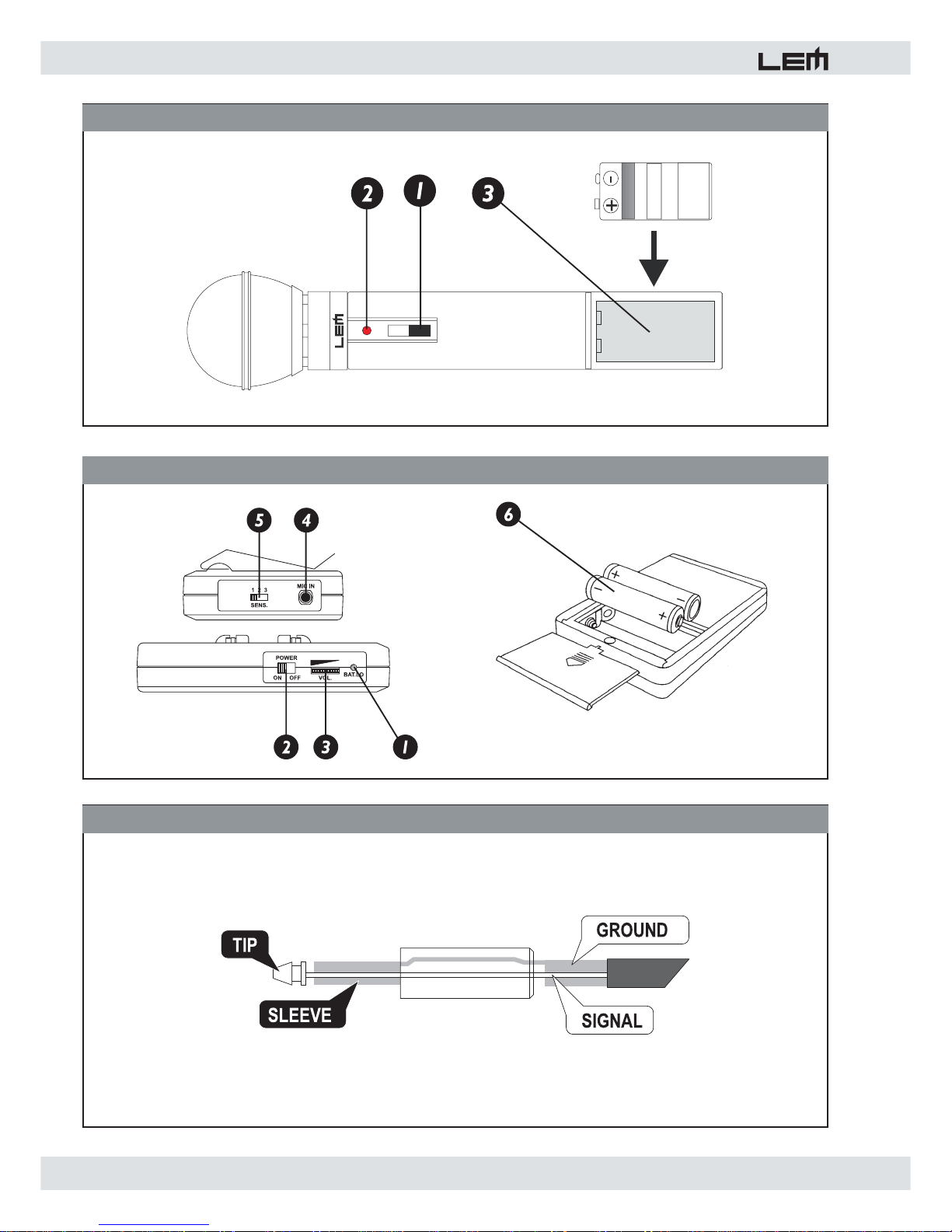
5. Microfono a mano . . . . . . . . . . . . . . . . . . . .4
6. Ricevitore bodypack . . . . . . . . . . . . . . . . . .4
7. Specifiche Tecniche. . . . . . . . . . . . . . . . . . .5
3. Norme di Installazione ed Uso
1. La protezione e la manutenzione.
Evitate di collocare il ricevitore in vicinanza di forti fonti
di calore e di esporlo direttamente alla luce solare, alla
pioggia, all’umidità, alla polvere o ad intense vibrazioni.
Non forzate manopole e interruttori: sono studiati per
rispondere ad una leggera pressione e potrebbero
essere danneggiati se usati con forza eccessiva. In
caso di avaria non aprite l'apparato, ma rivolgetevi al
più vicino Centro di Assistenza GENERALMUSIC.
2. Prevenzione di possibili disturbi.
Verificate che il luogo di installazione non presenti
disturbi industriali o a radio frequenza. Evitate
comunque di installare la vostra apparecchiatura in
stretta prossimità di apparecchi radio, TV, telefoni
cellulari, etc., in quanto questi potrebbero causare
interferenze rumorose.
3. Collegamento alla rete elettrica
Per alimentare il ricevitore usate esclusivamente
l'alimentatore in dotazione. Accertatevi, inoltre, che
la tensione di rete corrisponda a quella indicata
sull'alimentatore (è accettata una tolleranza fino
al ±10%) e che il cavo di alimentazione non sia
danneggiato e non presenti fili scoperti. Per evitare
pericolosi picchi di segnale effettuate i collegamenti
delle uscite dopo aver acceso il ricevitore o con il
volume del canale del mixer al minimo.
4. Collegamenti di segnale
Per il collegamento degli ingressi e delle uscite del
ricevitore usate solo cavi di segnale opportunamente
schermati. In dotazione al ricevitore ne viene fornito
uno di lunghezza 1mt. Verificate periodicamente che i
cavi impiegati siano in buono stato, con le connessioni
realizzate nel modo corretto e con tutti i contatti in
perfetta efficienza, in modo da evitare inconvenienti
come falsi contatti, rumori di massa, scariche, ecc.
4. Ricevitore (fig. 1)
1. ANTENNA
Antenna di ricezione (singola antenna in L100, doppia
antenna in L200).
2. POWER / VOLUME
Potenziometro per l'accensione del ricevitore e per
il controllo del livello del segnale. Regolate questo
controllo (ed eventualmente quello del trasmettitore
bodypack) in modo da ottenere il massimo livello
possibile senza distorsione.
3. ON
LED indicatore di ricevitore acceso/spento.
4. RF (L100) - A/B (L200)
Il modello L100 possiede un solo LED verde RF che
indica la presenza di segnale in ricezione.
Il modello L200 presenta due LED (verde e giallo) che
indicano quale delle due antenne A o B è correntemente
selezionata dal circuito SWITCHING DIVERSITY.

4
L100/L200
5. PEAK
LED rosso che segnala la presenza di segnale ad un
livello troppo alto. Regolate il controllo di volume del
ricevitore (e, eventualmente, quello del trasmettitore
bodypack) in modo da ottenere il massimo livello
possibile senza distorsione.
6.DC INPUT
Connettore per il collegamento dell’alimentatore
esterno.
7. OUTPUT
Uscita di LINEA con connettore JACK sbilanciato.
Collegate questa uscita all'ingresso LINE di uno dei
canali del mixer.
8. SQUELCH
Trimmer per il controllo della soglia di rumore. Permette
di eliminare eventuali interferenze presenti nel segnale.
Utilizzate un piccolo cacciavite per ruotarlo fino a che i
rumori indesiderati non scompaiono.
5. Microfono a Mano(fig. 2)
1. INTERRUTTORE
Interruttore per l’accensione e lo spegnimento del
microfono. Per prolungare la durata della batteria
spegnete sempre il microfono quando non è utilizzato.
2. LED ALIMENTAZIONE
Segnala l’accensione del microfono. Se all’accensione il
LED rimane spento, la batteria deve essere sostituita.
3. SOSTITUZIONE DELLA BATTERIA
Posizionate l’interruttore su OFF, svitate il fondo e
inserite solo batterie alcaline da 9V. La durata media di
una batteria di buona qualità è di 6-8 ore.
6. Trasmettitore Bodypack(fig. 3)
1. BAT. LO
LED indicatore dello stato delle batterie. Se lampeggia
brevemente al momento dell’accensione le batterie
sono ancora sufficientemente cariche. Se, invece,
rimane acceso (o se non si accende affatto) le batterie
sono esaurite e devono essere sostituite.
2. POWER ON/OFF
Interruttore di accensione/spegnimento.
3. VOLUME
Controllo del volume di uscita del trasmettitore.
4. MIC IN
Connettore di ingresso per il collegamento del
microfono.
5. SENS
Selettore di sensibilità di ingresso, da regolare a
seconda della sorgente collegata a MIC IN:
• posizione 1 = microfono LAVALIER (a condensatore)
• posizione 2 = microfono HEADSET (dinamico)
• posizione 3 = segnali di linea.
NOTA: Le posizioni 2 e 3 possono essere compatibili
anche con segnali provenienti da chitarre e
bassi elettrici. La posizione 1 eroga
l’alimentazione phantom: usatela solo con il
microfono LAVALIER in dotazione.
Per accedere al selettore fate scorrere il coperchio del
vano-portabatterie.
6. SOSTITUZIONE DELLA BATTERIA
Posizionate l’interruttore su OFF, fate scorrere il
coperchio del vano-portabatterie e inserite solo batterie
alcaline da 1.5V. La durata media di una batteria di
buona qualità è di 6-8 ore.

L100/L200
5
SPECIFICHE TECNICHE RICEVITORI
L100-RX L200-RX
Metodo di ricezione Controllo al quarzo, frequenza fissa,
singola antenna
Controllo al quarzo, frequenza fissa,
switching diversity
Banda di frequenza 170-240 MHz 170-240 MHz
Stabilità ± 0.005% / 25°C ± 0.005% / 25°C
Modulazione FM (F3E) FM (F3E)
Distorsione armonica totale < 0,8% < 0,8%
Rapporto segnale/rumore > 90 dB > 90 dB
Risposta in frequenza 50 Hz - 15 kHz, ±3dB 50 Hz - 15 kHz, ±3dB
Range dinamico > 100 dB > 100 dB
Sensibilità 3mV per 20dB Sinad 3mV per 20dB Sinad
Squelch Controllo esterno Controllo esterno
Uscite Jack sbilanciato, 0-300mV Jack sbilanciato, 0-300mV
Alimentazione DC 12V / 300mA
con alimentatore esterno
DC 12V / 300mA
con alimentatore esterno
Dimensioni (LxAxP) 152 x 98 x 36 mm 152 x 98 x 36 mm
Peso 260g 270g
SPECIFICHE TECNICHE TRASMETTITORI
L100/L200-HTX
Microfono a mano
L100/L200-BTX
Trasmettitore Bodypack
Tipo di microfono Dinamico Headset (dinamico
o Lavalier (condensatore)
Modulazione FM (F3E) FM (F3E)
Banda di frequenza 170-240 MHz 170-240 MHz
Stabilità ± 0.005% / 25 ± 0.005% / 25
Emissioni spurie 45dBc 45dBc
Potenza in uscita 15mW 15mW
Risposta in frequenza 50Hz ~ 15kHz 50Hz ~ 15KHz ± 3dB
Range dinamico > 100 dB > 100 dB
Batteria 1 x 6LR61 (9V Alkaline) 2 x LR03 (1.5V Alkaline)
Assorbimento 30mA (Max) 35mA (Max)
Durata batteria (alcalina) 6 - 8 ore 6 - 8 ore
Dimensioni 243mm 98 x 62 x 23 mm
Peso 215g 80g

6
L100/L200
1. Introduction
Congratulations for having chosen the L100/L200
wireless systems, the ideal solution for musicians and
audio engineers that require a very compact, easy-to-
use wireless microphone, suitable for a wide range of
applications.
Both systems operate in the VHF band (174-
223MHz) and can utilize 8 different frequencies for the
transmission (pre-set by the factory). The transmitter/
receiver radio frequency is showed on the products
package, on the rear panel of the receiver, on the
battery space inside the handheld microphone, on the
back of the bodypack transmitter.
L100 uses a single-antenna 'no-diversity' transmission
system.
L200 uses a SWITCHING DIVERSITY, double antenna
transmission system, with a circuit that automatically
selects the antenna receiving the best signal, reducing
breakdown and interference risks.
L100 and L200 are available in the following versions:
• HT version: with handheld microphone
• ST version: with headset mic
+ bodypack transmitter
• LT version: with lavalier mic
+ bodypack transmitter
• COMBI version: with the 3 kind of mic
+ bodypack transmitter
All the available versions include a 1/3 of rack receiver
and are housed in a very convenient plastic hard bag
for an easy handling.
To make the best use of this product, please read this
manual thoroughly before operating the equipment.
2. Contents
3. Instructions for use and installation . . . . . . .6
4. Receiver . . . . . . . . . . . . . . . . . . . . . . . . . . .6
5. Handheld microphone . . . . . . . . . . . . . . . . .7
6. Bodypack transmitter . . . . . . . . . . . . . . . . .7
7. Technical Specifications . . . . . . . . . . . . . . .8
3. Instructions for use and installation
1. Protection and maintenance.
To avoid jeopardizing correct operation, it is best
not to position your equipment for long periods in
exposed places (damp, high temperature, etc.), in dusty
environments or those subject to strong vibrations.
Do not force knobs and switches: they have been
designed to respond to a light touch and could be
damaged if treated with excessive force. In the event
of breakdown, do not open the unit, but contact the
nearest GENERALMUSIC Service Centre.
2. Prevention of possible interference.
First of all, check that the receiver is installed in a place
free from industrial or RF (radio frequency) interference.
Avoid installing your equipment very near radio or TV
sets, mobile phones, etc., as these can cause noisy
interference.
3. Connections.
The unit is supplied with an external power supply
adapter. Before switching on the unit, make certain
that the mains voltage matches that shown on the
power supply adapter (a tolerance of up to ±10% is
acceptable). Before switching on or off the apparatus
or connecting it to other equipment, make certain that
the mixer's channel is muted or the the sound system is
off: this will avoid dangerous signal peaks.
4. Connector cables.
When connecting the receiver to a mixer or to other
units, it’s suggested to use screened signal cables
made up of two wires plus a braid/screen: the use
of unscreened cables could in fact probably cause
annoying hum and noise. Check periodically that your
cables are in good condition, correctly wired and with
perfectly efficient contacts: in fact many problems and
drawbacks (false contacts, ground hum, crackles,
etc.) are caused by the use of unsuitable or damaged
cables.
4. Front Panel (fig. 1)
1. ANTENNA
Connector for connecting the antenna of the receiver
(sinlge antenna in the L100, double antenna in the
L200).
2. POWER / VOLUME
This potentiometer is used to switch ON the unit and
to control the signal level. Adjust the receiver’s volume
control (and the bodypack transmitter’s, if used) in order
to obtain the highestpossible distortion-free level.
3. ON
LED indicating when the unit is on.
4. RF (L100) - A/B (L200)
L100 has one green LED RF indicating signal detection
on the receiver’s input.
L200 has two LEDs (green and yellow) indicating which
antenna the receiver’s Switching Diversity circuitry has
selected

L100/L200
7
6. Transmitter Bodypack (fig. 3)
1. BAT. LO
Battery status LED. If this flashes briefly when switching
on, the batteries are sufficiently charged. If on the other
hand it remains lit (or off), this means the batteries are
flat and must be replaced.
2. POWER ON/OFF
ON/OFF switch.
3. VOLUME
Transmitter output volume control.
4. MIC IN
Input connector for connecting the microphone cable.
5. SENS
Input sensitivity selector. It must be set accordingly to
the unit connected to MIC IN:
• position 1 = LAVALIER microphone (condenser)
• position 2 = HEADSET microphone (dynamic)
• position 3 = line signals.
NOTE: Positions 2 and 3 can be suitable also for
electric guitar or bass signals. Position 1
supplies phantom power: use it only with the
supplied LAVALIER microphone.
Remove the cover of the battery slot to access to the
selector.
6. BATTERY REPLACEMENT
Set the switch at OFF, remove the cover of the battery
slot and install new batteries. Use only 2x1.5V alkaline
batteries. Good quality batteries normally last on
average 6-8 hours.
5. PEAK
When the red LED lights up, this means the level is too
high and will consequently distort. Adjust the receiver’s
volume control (and the bodypack transmitter’s, if used)
in order to obtain the highest possible distortion-free
level.
6. DC INPUT
Connector for connection to the external power supply.
7. OUTPUT
LINE output with unbalanced JACK connector. Connect
this output to a line input of the mixer.
8. SQUELCH
Trimmer for controlling the noise threshold. Enables
to eliminate any interference on the signal. Turn the
trimmer until any unwanted noise disappears.
5. Handheld Microphone (fig. 2)
1. SWITCH
Switch for switching the microphone on and off. For
longer battery life, always switch off the microphone
when not in use.
2. POWER SUPPLY LED
Shows that the microphone is on .If the LED doesn’t
light up when the microphone is switched on, replace
the battery
3. BATTERY REPLACEMENT
Set the switch at OFF, remove the bottom and install
a new battery. Use only 9V alkaline batteries. Good
quality batteries normally last on average 6-8 hours.

8
L100/L200
RECEIVER TECHNICAL SPECIFICATIONS
L100-RX L200-RX
Reception Mode Quartz-controlled, Fixed Frequency,
Single Antenna
Quartz-controlled, Fixed Frequency,
Switching Diversity
Frequency Range 170-240 MHz 170-240 MHz
Frequency Stability +/-0,005% / 25° C ± 0.005% / 25°C
Modulation Method FM (F3E) FM (F3E)
THD <0,8% < 0,8%
Signal/Noise Ratio >90 dB, A-weighted > 90 dB
Frequency Response 50 Hz - 15 kHz, ±3dB 50 Hz - 15 kHz, ±3dB
Dynamic Range >100 dB, A-weighted > 100 dB
RF Sensitivity 3mV per 20dB sinad 3mV per 20dB Sinad
Squelch External control External control
Output 1/4 Jack 0-300mV 1/4 Jack 0-300mV
Powering 12V DC / 300mA
with external power supply
12V DC / 300mA
with external power supply
Dimensions 152 X 98 X 36 mm 152 X 98 X 36 mm
Weight 260g 260g
TRANSMITTER TECHNICAL SPECIFICATIONS
L100/L200-HTX
Handheld Microphone
L100/L200-BTX
Bodypack Transmitter
Type of microphone Dynamic Headset (dynamic)
or Lavalier (condenser)
Modulation Method FM (F3E) FM (F3E)
Frequency Range 170-240 MHz 170-240 MHz
Frequency Stability ± 0.005% / 25 ± 0.005% / 25
Spurious Emissions 45dBc 45dBc
Transmission Power 15mW 15mW
Frequency Response 50Hz ~ 15kHz 50Hz ~ 15KHz ± 3dB
Dynami range > 100 dB > 100 dB
Powering 1 x 6LR61 (9V Alkaline) 2 x LR03 (1.5V Alkaline)
Power Consumption 30mA (Max) 35mA (Max)
Autonomy 6 - 8 hours 6 - 8 hours
Dimensions 243mm 98 x 62 x 23 mm
Weight 215g 80g

L100/L200
9
FIG. 1 - RECEIVER / RICEVITORE

10
L100/L200
FIG. 2 - HANDHELD MIC / MICROFONO A MANO
FIG. 3 - BODYPACK TRANSMITTER / TRASMETTITORE BODYPACK
FIG. 4 - CONNECTION CABLES / CAVI DI COLLEGAMENTO

L100/L200
11
FIG. 5 - Handheld Mic Connection / Collegamento Microfono a mano
FIG. 6 - Headset Mic Connection / Collegamento Mic Headset
FIG. 7 - Lavalier Mic Connection / Collegamento Mic Lavalier

Le informazioni contenute in questo documento sono state attentamente redatte e controllate. Tuttavia non
è assunta alcuna responsabilità per eventuali inesattezze.
Tutti i diritti sono riservati e questo documento non può essere copiato, fotocopiato, riprodotto per intero o
in parte senza previo consenso scritto della GENERALMUSIC S.p.A.
GENERALMUSIC si riserva il diritto di apportare senza preavviso cambiamenti e modifiche estetiche,
funzionali o di design a ciascun proprio prodotto.
GENERALMUSIC non assume alcuna responsabilità sull’uso o sull’applicazione dei prodotti o dei circuiti
qui descritti.
STAMPATO IN ITALIA
The information contained in this publication has been carefully prepared and checked. However no
responsibility will be taken for any errors.
All rights are reserved and this document cannot be copied, photocopied or reproduced in part or completely
without written consent being obtained in advance from GENERALMUSIC S.p.A.
GENERALMUSIC reserves the right to make any aesthetic, functional or design modification to any of its
products without any prior notice.
GENERALMUSIC assumes no responsibility for the use or application of the products or circuits described
herein.
PRINTED IN ITALY
FEDERAL COMMUNICATIONS COMMISSION
NOTE: This equipment has been tested and found to comply with the limits for a Class A digital device,
pursuant to Part 15 of FCC Rules. These limits are designed to provide reasonable protection against harmful
interference when the equipment is operated in a commercial environment. This equipment generates, uses
and can radiate radio frequency energy and, if not installed and used in accordance with the instruction
manual, may cause harmful interference to radio communications. Operations of this equipment in a
residential area is likely to cause harmful interference in which case the user will be required to correct the
interference at his own expense.
CAUTION: Changes or modifications to this product not expressly approved by the manufacturer could void
the user's authority to operate this product.
This manual suits for next models
4
Table of contents
Languages: