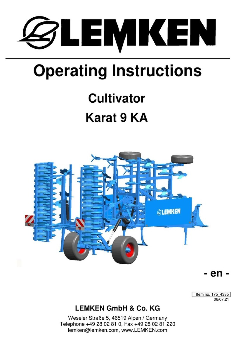
LEMKEN KARAT 10 User manual

OPERATING INSTRUCTIONS
Karat 10/300
Karat 10/350
Karat 10/400
Karat 10/300 U
Karat 10/350 U
Karat 10/400 U
INTENSIVE CULTIVATOR
KARAT 10
en-GB | Item no. 17516276 | BA 01/2023-09

Ensure that these instructions are always available when using the machine
and can be accessed by all users..
●
Keep these instructions for the entire service life of the machine.
●
Pass these instructions to all users / owners.
Original instructions
©2023 | This documentation is copyright protected. The copyright remains with LEMKEN GmbH & Co.
KG, Weseler Strasse 5, D-46519 Alpen.
The texts, diagrams and drawings must not be duplicated, distributed or disclosed in any other way,
either in whole or in part, without express approval.

Table of contents
1 About these instructions....................................................................................................................................... 1
1.1 Introduction......................................................................................................................................................... 1
1.2 Target groups...................................................................................................................................................... 3
1.3 Applied presentations..................................................................................................................................... 3
1.3.1 Signal words and hazard statements...................................................................................................... 3
1.3.2 Symbols and text markings........................................................................................................................ 4
1.3.3 Direction specications................................................................................................................................ 4
1.4 Further applicable documents..................................................................................................................... 5
2 Safety.............................................................................................................................................................................. 6
2.1 Machine limits..................................................................................................................................................... 6
2.2 Requirements of operators, users and service personnel................................................................... 7
2.3 General safety information............................................................................................................................ 8
2.4 Safety information on hazardous areas of the machine................................................................... 10
2.5 Safety information on structural modications................................................................................... 14
2.6 Safety information on situations............................................................................................................... 14
3 Design and description........................................................................................................................................ 16
3.1 Machine overview........................................................................................................................................... 16
3.2 Machine safety................................................................................................................................................. 20
3.2.1 Position of the label.................................................................................................................................... 20
3.2.2 Meaning of the labels................................................................................................................................. 21
3.2.3 Safety devices............................................................................................................................................... 24
3.3 Working tools................................................................................................................................................... 25
4 Commissioning........................................................................................................................................................ 26
4.1 Preparing an attachment............................................................................................................................. 26
4.1.1 Check machine for completeness......................................................................................................... 26
4.1.2 Ensuring suitability of the tractor.......................................................................................................... 26
4.2 Attaching the machine................................................................................................................................. 28
4.2.1 Practical knowledge - Eects of the mounting position............................................................... 28
4.2.2 Connecting the machine to the tractor............................................................................................... 33
5 Road travel................................................................................................................................................................. 39
5.1 Information on road travel........................................................................................................................... 39
5.2 Preparing for road travel.............................................................................................................................. 39
6 Operation................................................................................................................................................................... 41
6.1 Changing the setup state............................................................................................................................. 41
6.1.1 Converting the shares ............................................................................................................................... 41
6.1.2 Changing shares at the quick-change system.................................................................................. 44
6.1.3 Mounting the weed harrow..................................................................................................................... 46
Table of contents
en-GB | Item no. 17516276 | BA 01/2023-09 I

6.2 Adjusting the machine.................................................................................................................................. 47
6.2.1 Adjusting working depth.......................................................................................................................... 47
6.2.2 Adjusting share position........................................................................................................................... 52
6.2.3 Adjusting lateral limiter............................................................................................................................. 54
6.2.4 Adjusting rollers........................................................................................................................................... 55
6.3 Working with the machine.......................................................................................................................... 59
6.3.1 Standard procedure.................................................................................................................................... 59
6.3.2 Driving on the headland........................................................................................................................... 59
7 Cleaning and care................................................................................................................................................... 60
7.1 After working in the eld.............................................................................................................................. 60
7.2 Cleaning with high-pressure cleaner....................................................................................................... 60
8 Decommissioning................................................................................................................................................... 61
8.1 Detaching the machine................................................................................................................................ 61
8.2 Storing and wintering the machine......................................................................................................... 61
9 Maintenance and repair work.......................................................................................................................... 63
9.1 Maintaining the machine properly........................................................................................................... 63
9.1.1 Preparations.................................................................................................................................................. 63
9.1.2 During the maintenance and repair..................................................................................................... 64
9.2 Maintenance..................................................................................................................................................... 64
9.2.1 Maintenance schedule............................................................................................................................... 64
9.2.2 Tractor connection...................................................................................................................................... 66
9.2.3 Support wheels............................................................................................................................................. 66
9.2.4 Safety equipment........................................................................................................................................ 67
9.2.5 Hydraulics....................................................................................................................................................... 68
9.2.6 Electrics............................................................................................................................................................ 69
9.2.7 Checking the soil cultivation tools........................................................................................................ 69
9.2.8 Rollers............................................................................................................................................................... 70
9.3 Lubricating......................................................................................................................................................... 71
9.3.1 Lubrication schedule.................................................................................................................................. 71
9.3.2 Lubricating components via grease nipples..................................................................................... 72
9.3.3 Grease components.................................................................................................................................... 72
9.4 Work instructions............................................................................................................................................ 73
9.4.1 Replacing concave discs........................................................................................................................... 73
9.4.2 Replace the scrapers of the exring roller.......................................................................................... 74
10 Troubleshooting and error correction......................................................................................................... 75
10.1 Finding and eliminating errors correctly.............................................................................................. 75
10.2 Replacing the shear bolt............................................................................................................................ 76
Table of contents
en-GB | Item no. 17516276 | BA 01/2023-09II

11 Shutdown and disposal....................................................................................................................................... 77
11.1 Final decommissioning.............................................................................................................................. 77
11.2 Recycling and disposal .............................................................................................................................. 78
12 Technical data.......................................................................................................................................................... 79
12.1 About the technical data........................................................................................................................... 79
12.2 Dimensions..................................................................................................................................................... 79
12.3 Machine weights........................................................................................................................................... 79
12.4 Permissible mass and loads...................................................................................................................... 79
12.5 Required drawbar load............................................................................................................................... 80
12.6 Performance data......................................................................................................................................... 80
12.7 Connection data............................................................................................................................................ 80
12.7.1 Electrical connections.............................................................................................................................. 80
12.7.2 Hydraulic connections............................................................................................................................. 80
12.8 Noise, airborne sound................................................................................................................................. 81
12.9 Operating materials..................................................................................................................................... 81
12.10 Tyres and wheels........................................................................................................................................ 81
12.11 Connecting systems at the machine................................................................................................... 82
12.12 Permissible roller types............................................................................................................................ 82
Index............................................................................................................................................................................. 83
Appendix.................................................................................................................................................................... 87
A Type plate variants............................................................................................................................................ 88
B Tightening torques screws ............................................................................................................................. 89
C LEMKEN overview of operating materials................................................................................................. 95
D Calculation of axle load and ballasting for mounted machines....................................................... 97
E Cross shaft overview....................................................................................................................................... 101
Table of contents
en-GB | Item no. 17516276 | BA 01/2023-09 III

Table of contents
en-GB | Item no. 17516276 | BA 01/2023-09IV

1 About these instructions
1.1 Introduction
These operating instructions are important and belong to the
machine's scope of delivery.
These operating instructions must be available to the user at the place
of use.
nAlways read chapter "Safety" before using the machine for the rst
time.
nRead chapter "Operation - Basic operation" before using the
machine for the rst time.
nBefore starting work, also read the relevant steps in the operating
instructions.
INFORMATION
In other documents and in sections of these operating
instructions, the machine is also referred to as an imple‐
ment.
About these instructions
en-GB | Item no. 17516276 | BA 01/2023-09 1

These operating instructions describe operation of the machine after
initial commissioning by the LEMKEN sales partner and handover to the
operator.
Prior to operation, initial commissioning and instruction in operation,
setting/adjustment and maintenance must have been carried out.
These instructions describe the machine in combination with a tractor.
If the requirements placed on the tractor are also met by other
machines or vehicles, the respective description can also be applied
in these cases.
Operation of the tractor, including its relevant functions, is not part of
these operating instructions. The operator and the user are responsible
for observing the operating instructions of the tractor.
For an unambiguous assignment of this document to the machine,
transfer the following data from the type plate of the machine:
Designation on the type plate Enter the machine data here:
Series
Type designation
Model year
Serial number
Year of manufacture
INFORMATION
Position of the type plate on the machine:
Ä
Chapter 3 ‘Design and description’ on page 16
Explanation of the full type plate content:
Ä
Appendix A ‘Type plate variants’ on page 88
The machines can be equipped dierently at the factory.
Standard components, special equipment or optional accessories are
not marked separately.
The contents of these operating instructions, e.g. illustrations, may
therefore dier from the equipment of the machine.
Depending on the equipment, additional documents may be required
for operation.
INFORMATION
Ä
Chapter 1.4 ‘Further applicable documents’ on page 5
Validity range
Equipment variants
About these instructions
en-GB | Item no. 17516276 | BA 01/2023-092

1.2 Target groups
The target groups of these operating instructions are operators, users
and service personnel of the machine.
The target groups must meet the requirements for operators, users and
service personnel as dened in these instructions.
INFORMATION
Ä
Chapter 2.2 ‘Requirements of operators, users and service
personnel’ on page 7
1.3 Applied presentations
1.3.1 Signal words and hazard statements
The following signal words and hazard statements are used to label
warning signs and to warn of residual risks:
Signal word Meaning
DANGER Indicates an immediate hazardous situation
that may result in serious injury or death.
WARNING Indicates a hazardous situation that may
result in injury or death.
CAUTION Indicates a situation that may result in minor
injury.
Signal word Meaning
NOTICE Indicates a situation that may result in mate‐
rial damage.
Signal word Meaning
NOTE Indicates tips and useful information for the
user
ENVIRONMENTAL
PROTECTION
Indicates notices and special measures
regarding environmental protection
Warning of personal injury
Warning of property damage
Other notices and information
About these instructions
en-GB | Item no. 17516276 | BA 01/2023-09 3

1.3.2 Symbols and text markings
Symbol, text
marking
Meaning
In front of and in texts
●Marking for routine maintenance tasks
Activities that demand the help of service
sta.
nListing
[1], , Position numbers
Example: ‘Settings’ Software element
Example: [OK] Softkey, key, switch and button
[kg] Unit
ÄCross reference
In work instructions
√ Preconditions
►nWorking steps in single-step work
instructions
nMeasures for hazard avoidance in safety
information
1.
2.
Working steps in multi-step work instructions
ðResult
In illustrations
Light grey coloured
components
Non-relevant components, visible to facilitate
orientation
Yellow coloured com‐
ponents
Action-relevant components
1.3.3 Direction specications
The direction specications used in the text (left, right, front and rear)
refer to the driving direction of the tractor when moving forwards.
About these instructions
en-GB | Item no. 17516276 | BA 01/2023-094

1.4 Further applicable documents
Documents that are necessary and must be observed for operation:
nOperating instructions of the tractor
nFor partially assembled or disassembled delivery: Mounting instruc‐
tions
INFORMATION
The documents are regularly updated and brought into
line with any changes.
The latest versions of the documents can be found in the LEMKEN
Online Information System (LEONIS).
Users can access LEONIS directly via the QR code or the LEMKEN
website. In LEONIS, users can quickly nd the latest versions of their
instructions by setting lters.
Required documents
Latest versions of the documents
About these instructions
en-GB | Item no. 17516276 | BA 01/2023-09 5

2 Safety
2.1 Machine limits
The machine is used for soil cultivation on agricultural land.
It may only be used in accordance with the recognised rules of good
agricultural practice.
The permitted working depth is limited to the cultivatable soil horizons.
Use on heavily or deeply frozen soils, in soil horizons with unweathered
parent rock and soil horizons with loose rock or solid bedrock is not
regarded to be in compliance with the designated purpose.
Further information on the performance limits of the machine can be
found in
Ä
Chapter 12 ‘Technical data’ on page 79 of these operating
instructions.
The machine is carried or trailed by a suitable tractor. If necessary, other
functions of the machine are driven by the tractor.
How to check the suitability of a tractor is described in
Ä
Chapter
4.1.2 ‘Ensuring suitability of the tractor’ on page 26 of these operating
instructions.
The machine with the dened hazardous area is operated and moni‐
tored by the user on the tractor. When using an autonomous tractor,
monitoring by the autonomous tractor or additional systems must be
ensured.
The power supply to the machine is provided by the tractor and
includes hydraulic, electric and mechanical power.
The actual service life of a machine is not limited to a specic time
period as long as the machine is in ecient working order. The ecient
working order depends to a large extent on the operating conditions,
proper maintenance and the use of suitable operating materials, spare
parts and wearing parts in accordance with the operating instructions.
The dimensions of the machine must always be considered in combina‐
tion with the tractor.
The dimensions of the machine vary in the operating position and the
transport position and can be changed by swivelling components.
Information on the dimensions of the machine can be found in
Ä
Chapter 12 ‘Technical data’ on page 79 of these operating instruc‐
tions.
Intended use
Time limits
Spatial limits
Safety
en-GB | Item no. 17516276 | BA 01/2023-096

The machine and the area in the immediate vicinity of the machine
is deemed a hazardous area. This includes the space over the entire
width, length and height of the machine, as well as an additional safety
distance of two metres to the machine.
The hazardous area varies in the operating position and the transport
position and can be changed by swivelling components.
The hazardous area moves with the machine when it is moved.
2.2 Requirements of operators, users and service personnel
Operators within the meaning of these instructions are obliged to
inform all the users about correct application of the machine and the
respective hazards.
This can be done on the basis of these operating instructions. Opera‐
tors are responsible for ensuring that the operating instructions are
always available at the machine and that the users observe the oper‐
ating instructions.
Operators must also provide users with any necessary personal protec‐
tive gear.
Within the meaning of these instructions, users are persons who drive,
adjust, operate or maintain the machine. Users must be able to use the
machine safely.
This means:
nUsers understand how the machine works.
nUsers know and are able to avoid dangers.
nUsers are physically capable of controlling the machine.
In order to use the machine as intended and in a professional manner,
users must have the required technical (agricultural) knowledge.
Unless otherwise indicated, users may perform all of the activities
described in these operating instructions themselves.
Certain activities should only be performed by service personnel, e.g.
work on braking systems. These activities are indicated in the operating
instructions by the symbol .
Service personnel within the meaning of these instructions are all per‐
sons who maintain and repair safety-relevant components.
Service personnel are qualied for these activities based on their
training and expertise (for example agricultural machine mechanics).
Hazardous area
Operator
Users
Service personnel
Safety
en-GB | Item no. 17516276 | BA 01/2023-09 7

For the purposes of these instructions, qualied specialists are all per‐
sons who, on the basis of their professional training and experience,
carry out the tasks assigned to them in a professional manner. Qualied
specialists have knowledge of the relevant standards and regulations,
recognise possible hazards and avoid hazards independently.
2.3 General safety information
The operating instructions are part of the machine. The machine
is intended exclusively for use in accordance with these operating
instructions. Applications of the machine not described in these oper‐
ating instructions may result in personal injury or death or property
damage. If applications other than those described in the operating
instructions are planned, obtain the prior written consent of the manu‐
facturer. This also applies to unauthorised modications and alterations
to the machine.
►Observe the operating instructions and follow the working steps
given therein.
►Clarify questions of comprehension concerning the contents of
these operating instructions before starting work. If necessary, con‐
tact the manufacturer’s sales partner.
Damage to the machine can impair the operational safety of the
machine and cause accidents.
This may result in death or injuries.
In order to be able to operate the machine in a technically perfect
condition, carry out the following measures:
►Check the machine according to the maintenance schedule.
Ä
Chapter 9.2.1 ‘Maintenance schedule’ on page 64
►Repair damage and eliminate causes of damage immediately.
►Use original spare parts or parts approved by the manufacturer.
►Only use the auxiliary and operating materials listed.
►Remove coarse dirt.
If safety-relevant damage cannot be repaired in accordance with these
operating instructions:
►Have damage repaired by a qualied specialist workshop.
Qualied specialists
Operating instructions
Technically perfect condition
Safety
en-GB | Item no. 17516276 | BA 01/2023-098

Permissible spare parts are available from agroparts.
The QR code takes the user directly to agroparts. There, the user can
nd spare parts for the machine.
Existing and fully functional safety devices protect against death or
serious personal injury.
►Keep the labels legible and renew them, if necessary.
►Replace damaged safety devices.
►Install dismantled safety devices before commissioning.
►Move the safety devices to the protective position.
►In case of doubt whether all safety devices are properly installed
and fully functional: Commission a specialist workshop.
If the technical limits of the machine are not complied with, the func‐
tion of the safety devices may be impaired and the machine damaged.
This may result in death or injuries.
►Observe the machine-specic limit values.
Ä
Chapter 12 ‘Technical data’ on page 79
The machine is equipped with components in which mechanical
energy is stored (e.g. springs, overload safety units). Uncontrolled
release of mechanical energy accelerates components like a projectile.
This may result in death or injuries.
►Only allow components with stored energy to be dismantled or
opened by qualied specialists.
Spare parts
Safety equipment
Technical limit values
Stored mechanical energy
Safety
en-GB | Item no. 17516276 | BA 01/2023-09 9

The hydraulic assembly might be under high pressure.
Hydraulic oil leaking under pressure can penetrate through the skin
into the body.
Injury to body parts, face, eyes and unprotected skin may result.
The hydraulic assembly might be hot.
The hydraulic oil is harmful to health.
►NEVER touch leaks without hand protection.
Working on the hydraulic assembly:
nWear protective goggles and gloves.
nSwitch the hydraulic assembly to depressurised.
►Check the condition of the hydraulic assembly according to the
maintenance schedule.
►Replace damaged or worn components of the hydraulic
assembly immediately.
If hydraulic oil has entered the body: Risk of infection
nContact a doctor immediately.
nRemove the hydraulic oil from the body as quickly as possible.
Passengers may fall from the machine and seriously injure themselves.
Scattered objects may hit and injure passengers.
►NEVER allow persons to ride along on the machine.
2.4 Safety information on hazardous areas of the machine
The main workplace for working with the machine is the driver's seat in
the tractor. Further workplaces are described in the respective instruc‐
tions for action.
Dangerous situations may occur if several persons operate the machine
functions at the same time.
►Observe the hazardous areas.
►Pay attention to other persons in the vicinity of the machine.
Hydraulic assembly
NO passengers
Workplaces
Safety
en-GB | Item no. 17516276 | BA 01/2023-0910

When standing between the tractor and machine, there is a risk due to
tractor movements or sudden machine movements.
►Secure the tractor against rolling away.
►Before operating the linkage: Keep all persons away from the
movement area of the linkage.
A machine with a high dead weight can move downwards independ‐
ently.
This may result in death or injuries.
►NEVER walk or stand underneath unsecured machines.
►Use suitable equipment to secure machines against lowering.
Area between the tractor and
machine
Lifted machine
Safety
en-GB | Item no. 17516276 | BA 01/2023-09 11

The hazardous area of the machine during operation.
b
Moving hazardous area
b
The hazardous area includes the area in driving direction across the
entire width
b
of the machine.
There must be NO persons in the hazardous area.
If there are persons in the hazardous area, may result in death or injury
to persons.
►NEVER climb out of the tractor while it is moving.
►NEVER allow other persons to board the tractor while it is moving.
►In addition, maintain a safety distance of 2 m from the machine.
►While driving on the eld, observe the entire hazardous area. Stop
if required.
Moving hazardous area
Safety
en-GB | Item no. 17516276 | BA 01/2023-0912

b
c
Hazardous areas when folding the implement
b
c
There should be NO persons present in the folding range.
If persons are present in the folding range, it may result in death or
serious injury.
Lateral sections may, due to their height
c
touch overhead lines
during the folding processes and cause ashovers.
A ashover may result in death or serious injury.
Make certain before folding:
nDue to a risk of tipping: Machine is on a level surface with
sucient bearing capacity.
nNO persons are present in the folding range
b
.
nPersons keep a safe distance of 2 m to the folding range.
nThere are NO overhead lines in the vicinity of the machine.
After the drives have been switched o, the machine components
continue to run.
This may result in death or injuries.
►Only touch stationary components.
Folding range
Running machine components
Safety
en-GB | Item no. 17516276 | BA 01/2023-09 13

2.5 Safety information on structural modications
Structural modications and extensions can impair the functionality
and operational safety of the machine.
This may result in death or injuries.
Auxiliary equipment and spare parts must comply with the manufactur‐
er's requirements.
►Modications and conversions may only be carried out with the
written consent of the manufacturer.
►Structural modications and extensions must only be carried out
by an authorised specialist workshop.
►Use original spare parts or parts approved by the manufacturer.
►Only use the auxiliary and operating materials listed.
Ä
Chapter 12.9 ‘Operating materials’ on page 81
Improper welding work endangers the operational safety of the
machine.
This may result in death or injuries.
►Have welding work carried out by a qualied specialist workshop.
2.6 Safety information on situations
Mounted or trailed machines change the driving characteristics of the
tractor.
The driving characteristics also depend on the operating status, the
lling or loading and on the subsoil.
If the driver does not consider changed characteristics, accidents may
occur.
►Observe changed driving behaviour when driving.
Ä
Chapter 5 ‘Road travel’ on page 39
►If necessary, reduce the driving speed appropriately.
►Pay particular attention to the driving behaviour when driving on a
slope.
Structural modications
Welding work
Driving behaviour
Safety
en-GB | Item no. 17516276 | BA 01/2023-0914
This manual suits for next models
6
Table of contents
Other LEMKEN Tiller manuals
Popular Tiller manuals by other brands

Sears
Sears Craftsman 917.293550 owner's manual

Troy-Bilt
Troy-Bilt VersaTiller 12168 owner's manual

Simplicity
Simplicity 9108 Operator's manual

BE Ag & Industrial
BE Ag & Industrial AGRI EASE BE-TXG Series Operations & parts manual

Garland
Garland 741 RQG instruction manual

Dirty Hand Tools
Dirty Hand Tools 100983 Operation manual