Lemmer DC-5300 Use and care manual

For portable application of architectural paints and coatings. For professional use only.
Not approved for use in European explosive atmosphere locations.
3000 psi (20.7 MPa, 207 bar) Maximum Working Pressure
See page 3 for model information.
IMPORTANT SAFETY INSTRUCTIONS
Read all warnings and instructions in this manual and in gun manual.
Be familiar with the controls and the proper usage of the equipment.
Save all instructions.
Operation/Repair/Parts
DC-5300
Airless Paint Sprayer
Stand Model

Contents
2332882D
Contents
Contents . . . . . . . . . . . . . . . . . . . . . . . . . . . . . . . . . . 2
Models . . . . . . . . . . . . . . . . . . . . . . . . . . . . . . . . . . . 3
Warnings . . . . . . . . . . . . . . . . . . . . . . . . . . . . . . . . . 4
Component Identification . . . . . . . . . . . . . . . . . . . . 8
Operation . . . . . . . . . . . . . . . . . . . . . . . . . . . . . . . . . 9
Grounding . . . . . . . . . . . . . . . . . . . . . . . . . . . . . . 9
Pails . . . . . . . . . . . . . . . . . . . . . . . . . . . . . . . . . 10
Pressure Relief Procedure . . . . . . . . . . . . . . . . 10
Setup . . . . . . . . . . . . . . . . . . . . . . . . . . . . . . . . . 11
Prime and Flush Storage Fluid . . . . . . . . . . . . . 11
Flushing . . . . . . . . . . . . . . . . . . . . . . . . . . . . . . 11
Startup . . . . . . . . . . . . . . . . . . . . . . . . . . . . . . . 12
Clearing Clogs . . . . . . . . . . . . . . . . . . . . . . . . . 13
Adjusting the Pressure . . . . . . . . . . . . . . . . . . . 13
Shutdown . . . . . . . . . . . . . . . . . . . . . . . . . . . . . 13
Storage . . . . . . . . . . . . . . . . . . . . . . . . . . . . . . . 13
Maintenance . . . . . . . . . . . . . . . . . . . . . . . . . . . . . . 14
Daily Maintenance . . . . . . . . . . . . . . . . . . . . . . . 14
Electric Motor Maintenance . . . . . . . . . . . . . . . . 14
Servicing the Fluid Pump . . . . . . . . . . . . . . . . . . 14
Fluid Pump Disconnect . . . . . . . . . . . . . . . . . . . 14
Servicing the Inlet Valve - Hi-Boy . . . . . . . . . . . 16
Servicing the Inlet Valve - Stand . . . . . . . . . . . . 16
Packing Replacement Procedures . . . . . . . . . . 16
Gear and Pump Assembly . . . . . . . . . . . . . . . . . 18
Replacement of Electrical Components . . . . . . 19
Troubleshooting . . . . . . . . . . . . . . . . . . . . . . . . . . . 20
Parts . . . . . . . . . . . . . . . . . . . . . . . . . . . . . . . . . . . . 22
Manifold Filter (868014) . . . . . . . . . . . . . . . . . . . 22
Inlet Valve . . . . . . . . . . . . . . . . . . . . . . . . . . . . . 22
Stand Frame Parts Diagram . . . . . . . . . . . . . . . 23
Hi-Boy Parts Diagram . . . . . . . . . . . . . . . . . . . . 24
Control Parts Diagram . . . . . . . . . . . . . . . . . . . . 25
Motor and Drive Parts Diagram . . . . . . . . . . . . . 26
Drive Parts . . . . . . . . . . . . . . . . . . . . . . . . . . . . . 27
Packing Replacement . . . . . . . . . . . . . . . . . . . . 28
Suction Assemblies . . . . . . . . . . . . . . . . . . . . . . 29
Electrical System . . . . . . . . . . . . . . . . . . . . . . . . 30
Technical Data . . . . . . . . . . . . . . . . . . . . . . . . . . . . 31

3

Warnings
4
Warnings
The following warnings are for the setup, use, grounding, maintenance, and repair of this equipment. The exclama-
tion point symbol alerts you to a general warning and the hazard symbols refer to procedure-specific risks. When
these symbols appear in the body of this manual or warning labels, refer back to these Warnings. Product-specific
hazard symbols and warnings not covered in this section may appear throughout the body of this manual where
applicable.
WARNING
WARNINGWARNING
GROUNDING
This product must be grounded. In the event of an electrical short circuit, grounding reduces the risk of
electric shock by providing an escape wire for the electric current. This product is equipped with a cord
having a grounding wire with an appropriate grounding plug. The plug must be plugged into an outlet that
is properly installed and grounded in accordance with all local codes and ordinances.
• Improper installation of the grounding plug is able to result in a risk of electric shock.
• When repair or replacement of the cord or plug is required, do not connect the grounding wire to either
flat blade terminal.
• The wire with insulation having an outer surface that is green with or without yellow stripes is the
grounding wire.
• Check with a qualified electrician or serviceman when the grounding instructions are not completely
understood, or when in doubt as to whether the product is properly grounded.
• Do not modify the plug provided; if it does not fit the outlet, have the proper outlet installed by a qual-
ified electrician.
• This product is for use on a nominal 120V circuit and has a grounding plug similar to the plug illustrated
in the figure below.
• Only connect the product to an outlet having the same configuration as the plug.
• Do not use an adapter with this product.
Extension Cords:
• Use only a 3-wire extension cord that has a grounding plug and a grounding receptacle that accepts
the plug on the product.
• Make sure your extension cord is not damaged. If an extension cord is necessary, use 12 AWG (2.5
mm2) minimum to carry the current that the product draws.
• An undersized cord results in a drop in line voltage and loss of power and overheating.
120V US

Warnings
5
WARNING
WARNINGWARNING
FIRE AND EXPLOSION HAZARD
Flammable fumes, such as solvent and paint fumes, in work area can ignite or explode. To help prevent
fire and explosion:
• Do not spray or clean with materials having flash points lower than 100° F (38° C). Use only non-flam-
mable or water-based materials, or non-flammable paint thinners. For complete information about your
material, request the SDS from the material distributor or retailer.
• Do not spray flammable or combustible materials near an open flame or sources of ignition such as cig-
arettes, motors, and electrical equipment.
• Paint or solvent flowing through the equipment is able to result in static electricity. Static electricity cre-
ates a risk of fire or explosion in the presence of paint or solvent fumes. All parts of the spray system,
including the pump, hose assembly, spray gun, and objects in and around the spray area shall be prop-
erly grounded to protect against static discharge and sparks. Use Graco conductive or grounded
high-pressure airless paint sprayer hoses.
• Verify that all containers and collection systems are grounded to prevent static discharge. Do not use
pail liners unless they are anti-static or conductive.
• Connect to a grounded outlet and use grounded extension cords. Do not use a 3-to-2 adapter.
• Do not use a paint or a solvent containing halogenated hydrocarbons.
• Do not spray combustible liquids in a confined area.
• Keep spray area well-ventilated. Keep a good supply of fresh air moving through the area.
• Spray generates sparks. Keep pump assembly in a well-ventilated area at least 20 feet (6.1 m) from the
spray area when spraying, flushing, cleaning, or servicing. Do not spray pump assembly.
• Do not smoke in the spray area or spray where sparks or flame is present.
• Do not operate light switches, engines, or similar spark producing products in the spray area.
• Keep area clean and free of paint or solvent containers, rags, and other flammable materials.
• Know the contents of the paints and solvents being sprayed. Read all Safety Data Sheets (SDS) and
container labels provided with the paints and solvents. Follow the paint and solvents manufacturer’s
safety instructions.
• Fire extinguisher equipment shall be present and working.
ELECTRIC SHOCK HAZARD
This equipment must be grounded. Improper grounding, setup, or usage of the system can cause electric
shock.
• Turn off and disconnect power cord before servicing equipment.
• Use only grounded electrical outlets.
• Use only 3-wire extension cords.
• Ensure ground prongs are intact on power and extension cords.
• Do not expose to rain. Store indoors.

Warnings
6
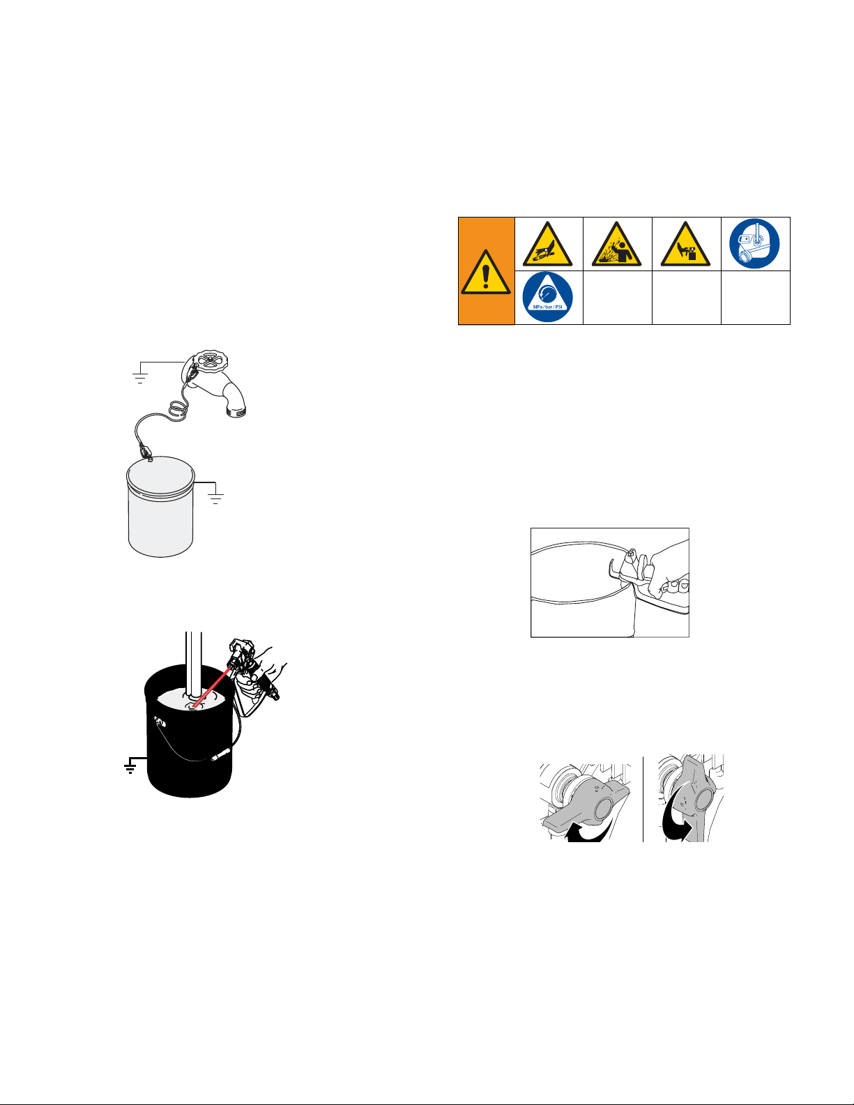
SKIN INJECTION HAZARD
High-pressure spray is able to inject toxins into the body and cause serious bodily injury. In the event that
injection occurs, get immediate surgical treatment.
• Do not aim the gun at, or spray any person or animal.
• Keep hands and other body parts away from the discharge. For example, do not try to stop leaks with
any part of the body.
• Always use the nozzle tip guard. Do not spray without nozzle tip guard in place.
• Use Graco nozzle tips.
• Use caution when cleaning and changing nozzle tips. In the case where the nozzle tip clogs while
spraying, follow the Pressure Relief Procedure for turning off the unit and relieving the pressure
before removing the nozzle tip to clean.
• Equipment maintains pressure after power is shut off. Do not leave the equipment energized or under
pressure while unattended. Follow the Pressure Relief Procedure when the equipment is unattended
or not in use, and before servicing, cleaning, or removing parts.
• Check hoses and parts for signs of damage. Replace any damaged hoses or parts.
• This system is capable of producing 3000 psi. Use Graco replacement parts or accessories that are
rated a minimum of 3000 psi.
• Always engage the trigger lock when not spraying. Verify the trigger lock is functioning properly.
• Verify that all connections are secure before operating the unit.
• Know how to stop the unit and bleed pressure quickly. Be thoroughly familiar with the controls.
EQUIPMENT MISUSE HAZARD
Misuse can cause death or serious injury.
• Always wear appropriate gloves, eye protection, and a respirator or mask when painting.
• Do not operate or spray near children. Keep children away from equipment at all times.
• Do not overreach or stand on an unstable support. Keep effective footing and balance at all times.
• Stay alert and watch what you are doing.
• Do not operate the unit when fatigued or under the influence of drugs or alcohol.
• Do not kink or over-bend the hose.
• Do not expose the hose to temperatures or to pressures in excess of those specified by Graco.
• Do not use the hose as a strength member to pull or lift the equipment.
• Do not spray with a hose shorter than 25 feet.
• Do not alter or modify equipment. Alterations or modifications may void agency approvals and create
safety hazards.
• Make sure all equipment is rated and approved for the equipment in which you are using it.
PRESSURIZED ALUMINUM PARTS HAZARD
Use of fluids that are incompatible with aluminum in pressurized equipment can cause serious chemical
reaction and equipment rupture. Failure to follow this warning can result in death, serious injury, or prop-
erty damage.
• Do not use 1,1,1-trichloroethane, methylene chloride, other halogenated hydrocarbon solvents or fluids
containing such solvents.
• Do not use chlorine bleach.
• Many other fluids may contain chemicals that can react with aluminum. Contact your material supplier
for compatibility.
WARNING
WARNINGWARNING

Warnings
7
MOVING PARTS HAZARD
Moving parts can pinch, cut or amputate fingers and other body parts.
• Keep clear of moving parts.
• Do not operate equipment with protective guards or covers removed.
• Pressurized equipment can start without warning. Before checking, moving, or servicing equipment,
follow the Pressure Relief Procedure and disconnect all power sources.
TOXIC FLUID OR FUMES HAZARD
Toxic fluids or fumes can cause serious injury or death if splashed in the eyes or on skin, inhaled, or swal-
lowed.
• Read Safety Data Sheet (SDS) to know the specific hazards of the fluids you are using.
• Store hazardous fluid in approved containers, and dispose of it according to applicable guidelines.
PERSONAL PROTECTIVE EQUIPMENT
Wear appropriate protective equipment when in the work area to help prevent serious injury, including
eye injury, hearing loss, inhalation of toxic fumes, and burns. Protective equipment includes but is not lim-
ited to:
• Protective eyewear, and hearing protection.
• Respirators, protective clothing, and gloves as recommended by the fluid and solvent manufacturer.
CALIFORNIA PROPOSITION 65
This product contains a chemical known to the State of California to cause cancer, birth defects or other
reproductive harm. Wash hands after handling.
WARNING
WARNINGWARNING

Component Identification
8
Component Identification
ti22321a
A
B
C
D
E
A Power switch Turns sprayer ON and OFF
B Pressure Control Knob Adjusts pressure. Turn clockwise to increase pressure and coun-
terclockwise to decrease pressure.
C Prime Valve Primes pump.
D Prime Valve Open Position Valve is in open position when handle is in the vertical position.
E Prime Valve Closed Position Valve is in closed position when handle is in the horizontal posi-
tion.

Operation
9
Operation
Grounding
Air and fluid hoses: use only electrically conductive
hoses with a maximum of 500 ft. (150 m) combined
hose length to ensure grounding continuity. Check elec-
trical resistance of hoses. If total resistance to ground
exceeds 29 megohms, replace hose immediately.
Spray gun: ground through connection to a properly
grounded fluid hose and pump.
Fluid supply container: follow local code.
Object being sprayed: follow local code.
Solvent pails used when flushing: follow local code.
Use only conductive metal pails, placed on a grounded
surface. Do not place the pail on a non-conductive sur-
face, such as paper or cardboard, which interrupts
grounding continuity.
To maintain grounding continuity when flushing or
relieving pressure: hold metal part of the spray
gun/dispense valve firmly to the side of a grounded
metal pail, then trigger the gun/valve.
The sprayer cord includes a grounding wire with an
appropriate grounding contact.
The plug must be plugged into an outlet that is properly
installed and grounded in accordance with all local
codes and ordinances.
Do not modify the plug provided; if it does not fit the
outlet, have the proper outlet installed by a qualified
electrician.
Extension Cords: Use an extension cord with an
undamaged ground contact. If an extension cord is nec-
essary, use a 3-wire, 12 AWG (2.5 mm2) minimum.
NOTE: Smaller gauge or longer extension cords may
reduce sprayer performance.
The equipment must be grounded to reduce the risk
of static sparking and electric shock. Electric or static
sparking can cause fumes to ignite or explode.
Improper grounding can cause electric shock.
Grounding provides an escape wire for the electric
current.
TIC

Operation
10
Pails
Solvent and oil/based fluids: follow local code. Use
only conductive metal pails, placed on a grounded sur-
face such as concrete.
Do not place pail on a non-conductive surface such as
paper or cardboard which interrupts grounding
continuity.
Grounding a metal pail: connect a ground wire to the
pail by clamping one end to pail and other end to a true
earth ground such as a water pipe.
To maintain grounding continuity when flushing or
relieving pressure: hold metal part of spray gun firmly
to side of a grounded metal pail. Then trigger gun.
Pressure Relief Procedure
Follow this Pressure Relief Procedure whenever you
stop spraying and before cleaning, checking, servicing,
or transporting equipment.
1. Engage the gun trigger lock. Refer to the separate
instruction manual provided with gun for safety fea-
tures and how to engage the trigger lock.
2. Turn the unit off.
3. Disengage the gun trigger lock and trigger the gun
to relieve residual fluid pressure.
Hold metal part of the gun in contact with grounded
metal pail. Use minimum pressure.
4. Re-engage gun trigger lock and turn Prime Valve to
the open (priming) position.
NOTE: The valve handle can move both clockwise and
counter clockwise and can face different directions.
NOTE: If you suspect the spray tip or hose is clogged or
that pressure has not been fully relieved after following
the steps above, VERY SLOWLY loosen tip guard
retaining nut or hose end coupling to relieve pressure
gradually, then loosen completely. Clear hose or tip
obstruction.
ti5851a
ti5310b
ti15989a
Closed
(Pressure)
Open
(Priming)
ti17403a

Operation
11
Setup
Connect the hose and gun
1. Remove the plastic cap plug from the outlet and
screw a conductive or grounded 3000 psi spray
hose onto fluid outlet.
2. Connect an airless spray gun to the other end of the
hose. Do not install spray tip.
Fill the Packing Nut/Wet Cup
1. Remove guard and cap.
2. Fill the Packing Nut/Wet Cup with 5 drops of Throat
Seal Oil (TSO) or Packing Seal Fluid.
Flush the Sprayer
1. Flush the sprayer. See Flushing Procedure on
page 11.
Prime and Flush Storage Fluid
Before beginning a new spraying project you need to
prime the sprayer and flush the storage fluid out of the
sprayer.
Oil- or Water-based Materials
• When changing from water-based material to oil
based material, flush with soapy water and then
mineral spirits.
• When changing from oil based material to water
base material, flush with mineral spirits, followed by
soapy water, then a clean water flush.
• When flushing with solvents, ground pail and gun.
• Flush before changing colors, before fluid can dry in
the equipment, at the end of the day, before storing,
and before repairing equipment.
Flushing
1. Make sure the gun trigger lock is engaged and there
is no spray tip in the gun. Refer to the separate
instruction manual provided with gun for safety fea-
tures and how to engage the trigger lock.
2. Pour enough clean, compatible solvent into a large,
empty metal pail to fill the pump and hoses.
3. Place the suction tube into the pail or place the pail
under the pump.
M
To reduce the risk of static sparking, fire or explosion
which can result in serious bodily injury and property
damage. Always ground the sprayer and system
components and the object being sprayed. Ensure
proper electrical service and amperage and that the
outlet is properly grounded.
NOTICE
The equipment was tested with lightweight oil, which
is left in the fluid passages to protect parts. To avoid
contaminating your fluid with oil, flush the equipment
with a compatible solvent before using the equipment
for the first time.
ti16049a
M M
• To reduce the risk of static sparking, which can
cause fire or explosion, always hold a metal part
of the gun firmly against the metal pail when flush-
ing. This also reduces splashing.
• To reduce risk of injection, always remove the
spray tip before flushing to avoid.
ti16028a

Operation
12
4. Turn Pressure Control Knob to low.
5. Open the prime valve to the open (priming) position.
This will allow an easy start.
6. Turn the power ON/OFF switch to ON.
7. Point the gun into the metal pail and hold a metal
part of the gun firmly against the pail. Maintain firm
metal to metal contact between gun and container.
8. Disengage the gun trigger lock and squeeze the
trigger. At the same time, slowly turn the pressure
control knob clockwise, just enough to move liquid
at low pressure.
9. Allow the pump to operate until clean solvent comes
from the gun.
10. Release the trigger and engage the gun trigger lock.
11. If you are going to start spraying, place the pump or
suction tube into the supply container. Release the
gun trigger lock and trigger the gun into another
empty, metal container, holding a metal part of the
gun firmly against the metal pail, forcing the solvent
from the pump and hose. When paint starts coming
from gun, turn pressure control knob to minimum
pressure, place prime valve in prime (open) position
and engage the gun trigger lock.
12. If you are going to store the sprayer see Storage,
page 13. Engage the gun trigger lock.
13. Whenever shutting down the sprayer, follow Pres-
sure Relief Procedure, page 10.
Startup
1. Prepare the material according to the material man-
ufacturer’s recommendations.
2. Place the suction tube into the material container.
3. Start the sprayer.
a. Prime Valve must be in the open (priming) posi-
tion.
b. After ensuring the gun trigger lock is engaged,
attach tip and safety guard.
c. Turn the power ON/OFF switch to the “ON”
position.
d. Turn the Pressure Control Knob clockwise to
prime the pump.
e. After the pump is primed, turn the Prime Valve
to the “CLOSED” position.
f. Turn Pressure Control Knob to the desired
spray pressure.
g. Disengage the gun trigger lock to begin spray-
ing.
4. To stop the unit in an emergency, turn the engine
off. then relieve the fluid pressure in the pump and
hose. See Pressure Relief Procedure, page 10.
ti22322a
Closed
(Pressure)
Open
(Priming)
ti17403a
ti15989a
NOTICE
To prevent damage and freezing during storage,
never leave water in the fluid pump

Operation
13
Clearing Clogs
1. Release trigger. Engage trigger lock. Rotate Spray
Tip. Disengage trigger lock. Trigger gun at waste
area to clear clog.
2. Engage trigger lock. Return Spray Tip to original
position. Disengage trigger lock and continue
spraying.
Adjusting the Pressure
When adjusting the pressure, turn the Pressure Control
Knob clockwise to increase pressure and counterclock-
wise to decrease pressure. Always use the lowest pres-
sure necessary to completely atomize the material. If
more coverage is needed, use a larger tip rather than
increasing the pressure.
NOTE: Operating the sprayer at higher pressure than
needed wastes material, causes early tip wear, and
shortens sprayer life.
NOTE: Check the spray pattern. The tip size and angle
determines the pattern width and flow rate.
Shutdown
1. Relieve Pressure, page 10.
2. Clean the tip and gun as recommended in the sepa-
rate Gun Manual supplied with the gun.
3. If spraying water-based material or a material that
could harden in the sprayer overnight, flush the
sprayer after use. See Flushing, page 11.
Storage
Short Term
1. Flush sprayer with compatible solvent before stor-
ing, then fill the pump and hoses with an oil based
solvent such as mineral spirits.
• For oil base paint: flush with mineral spirits
• For water-base paint: flush with water, then min-
eral spirits and leave the pump, hose and gun
filled with mineral spirits.
Long Term
For longer storage, use Graco Pump Armor or mineral
spirits. Shut off sprayer, Relieve Pressure, page 10,
and make sure prime valve is left open.
Start Up After Storage
Before using water-base paint, flush sprayer with soapy
water and then a clean water flush. When using oil-base
paint, flush out the mineral spirits with the material to be
sprayed.
NOTE: Always store unit indoors.
To reduce the risk of injection, never hold your hand,
body, fingers or hand in a rag in front of the spray tip
when cleaning or checking for a cleared tip. Always
point the gun toward the ground or into a waste con-
tainer when checking to see if the tip is cleared or
when using a self cleaning tip.
ti10166a ti22227a ti10167a
ti10166a ti22226a ti10167a

Maintenance
14
Maintenance
Daily Maintenance
1. Keep the displacement pump packing nut/wet cup
lubricated with Throat Seal Oil (TSO) or Packing
Seal Fluid at all times. The oil or fluid help protect
the rod and packings.
2. Inspect the packing nut daily. If seepage of paint
into the packing nut and/or movement of the piston
upward is found (while not spraying), the packing
nut should be tightened just enough to stop leakage
(torque is 24 in-lbs). Over tightening will damage the
packings and reduce the packing life.
Electric Motor Maintenance
Lubrication
The motor is supplied with pre-lubricated ball bearings,
lubricated for the life of the bearing.
Motor Brushes
Motor brushes need periodic inspection and replace-
ment as wear indicates. Standard brushes have an ini-
tial length of 1” and should be replaced when they are
worn to a length of 1/2”. Brush wear is greatly influenced
by individual application and it is recommended that
brush wear be checked at early intervals of operation in
order to determine future required inspection.
To change the brushes:
1. Disconnect power from the unit.
2. Remove the cover over the motor, if applicable.
3. Open the two covers at the rear of the motor.
4. Disconnect the brush wire.
5. Pull out the wire.
6. Push the brush retainer clip in and withdraw.
7. Remove the worn brushes.
8. Install new brushes in the reverse order.
9. To increase brush life, new brushes (Part # 331780)
need to have a run in period. After changing
brushes, set the machine for spraying. With a
bucket of Pump Conditioner and water, a 50’ 1/4”
airless hose, airless gun and tip on unit, open the
prime valve and power on. The pump will now
prime. With pump running in the prime mode, turn
the pressure control knob to high pressure. (The
pump has to cycle fast with no pressure in the
pump). Run the pump for 20 minutes and the
brushes will be run in.
Servicing the Fluid Pump
Fluid Pump Disconnect
1. Relieve Pressure, page 10.
2. Flush the material you are spraying out of the
machine.
3. Remove the connecting rod shield(12).
4. Move the piston rod (10) to its lowest position by
cycling pump slowly.
5. Turn off the motor and disconnect power from unit.
6. Remove the retaining ring (4) from the connecting
rod (2) and slide the sleeve (3) down revealing the
connecting rod pin (1).
7. Remove the suction tube assembly from the fluid
pump (9) by unscrewing the suction nut (7) with the
packing adjustment tool. (865008).
8. Using a 1/2” wrench, unscrew the two bolts (8) from
the cover assembly (14). The fluid pump (9) will be
hanging loosely at this point.
9. Remove the connecting rod pin (1) out of the con-
necting rod (2), allowing the removal of the fluid
pump (9) from the machine.
ti16051a
Brush Kit
331780

Maintenance
15
Fluid Pump Reinstall
1. Loosen the packing nut and ensure that the piston
rod (10) is in its upper position in the fluid pump
body, snap cap onto packing nut and slip the sleeve
(3) and the retaining ring (4) over the piston rod
(10).
2. Push the piston rod (10) up into the connecting rod
(2) and align the holes. Insert the connecting rod pin
(1) through the connecting rod (2) and piston. Slip
the sleeve (3) up over the connecting rod pin (1) and
insert the retaining ring (4) into the groove on the
connecting rod (2).
3. Push the two bolts (8) through the tube spacers (11)
and screw them into the cover assembly. Using a
1/2” wrench, tighten the two bolts (8) evenly (alter-
nating between them) to 20 ft-lbs (27.1 N•m).
4. For Hi-Boy: Reassemble lower suction valve
assembly by placing the suction seat, O-ring, suc-
tion ball and suction ball guide in the suction nut (7)
and screw onto fluid pump body.
For Stand: Reassemble lower suction valve assem-
bly by placing the o-ring, PTFE-ring on stop of ball
cage, o-ring on bottom of ball cage in the suction nut
(7) and screw onto fluid pump body.
5. Reconnect the pressure control knob and fitting to
the fluid pump body.
6. Start the machine and operate slowly to check the
piston rod (10) for binding. Adjust the two bolts (8),
holding the fluid pump body to the cover assembly,
if necessary. This will eliminate any binding.
7. Tighten packing nut clockwise until resistance is felt
against the Belleville Springs, go 3/4 of a turn more.
Put five drops of Throat Seal Oil or Packing Seal
Fluid in the packing nut.
8. Run the machine at full pressure for several min-
utes. Release the pressure by following the Pres-
sure Relief Procedure, page 10, and readjust the
packing nut per step 7 above.
9. Install the connection rod shield (12).
ti22323b

Maintenance
16
Servicing the Inlet Valve - Hi-Boy
1. Relieve Pressure, page 10. Disconnect power from
unit.
2. Un-thread and remove suction nut from the fluid
pump body (8).
3. Remove suction seat assembly (12).
4. Clean all parts and inspect them for wear or dam-
age, replacing parts as needed.
5. Clean inside of the fluid pump body (8).
6. Reassemble lower suction valve assembly by plac-
ing the suction seat assembly (12) in the suction nut
(13) and screw onto fluid pump body (8).
Servicing the Inlet Valve - Stand
1. Relieve Pressure, page 10. Disconnect power from
unit.
2. Un-thread and remove suction nut from the fluid
pump body (8).
3. Remove O-ring (158), suction seat assembly (157),
O-ring (159) and backup ring (160).
4. Clean all parts and inside fluid body (8).
5. Reassemble inlet valve with O-ring (159), backup
ring (160) and O-ring (158).
6. Tighten suction nut using packing adjustment tool
(865008).
Packing Replacement
Procedures
Disassembly of the Fluid Pump
1. Disconnect the Fluid Pump, page 14.
2. Unscrew and remove the packing nut, with wet cup
cap.
3. Push the piston rod down through the packings and
out of the pump.
4. Push the packing removal tool up through the pump
and remove from the top, bringing packings, spacer
and springs along with it, leaving fluid body empty.
Make sure all old packings and glands have been
removed from fluid pump.
5. Clean inside of fluid body.
6. Disassemble all parts and clean for reassembly.
Discard any old packings.
7. Lubricate leather packing in lightweight oil for 10
minutes prior to reassembly.
Reassembly of the Fluid Pump
1. Place lower male gland (1) down on the flat side.
2. Take three of the lower polyethylene packings (2)
and two of the leather packings (23) and place onto
the male gland (1), with the inverted side down, in
the following order:
• Polyethylene
• Leather
• Polyethylene
• Leather
• Polyethylene
3. Take the female adapter (3), which is inverted on
both sides, and place it on top of your assembled
lower packings.
4. Follow step 2 with your packings inverted side up.
5. Take the second lower male gland (1) and place it
on top of your assembled packings with rounded
side down.
6. Take assembled glands and packings (13 pieces)
and slide onto the lower half of the piston (14).
7. Take the spacer (15) and slide over the top of the
piston (14).
8
9
10
11
12
13
159
160
157
158
ti16056b
Stand Model

Maintenance
17
8. Take three spring washers (16) and slide over the
top of the piston (14) in the following order:
• First spring - curve facing up
• Second spring - curve facing down
• Third spring - curve facing up
9. Take the upper male gland (17) and place it
rounded side up.
10. Take three upper polyethylene packings (18) and
two leather packings (22) and assemble with
inverted side down, on to the male gland (17) in the
following order:
• Polyethylene
• Leather
• Polyethylene
• Leather
• Polyethylene
11. Take upper female gland (19) and place on top of
assembled upper packings with the inverted side
down.
12. Take assembled upper glands and packings (7
pieces) and slide on over the top of the piston (14),
making sure inverted sides are down.
13. Take the packing holder (20) and replace the white
O-ring (24) and the black O-ring (25) with new ones
from the packing kit.
14. Slide the packing holder (20) over the top fo the
upper packings so they fit inside.
15. Lubricate inside of the fluid pump body (4) and the
outside of the packings with a light weight oil.
16. Slide assembly into fluid pump body.
NOTE: To keep packings secured in correct position,
hold the pump body upside down and push the com-
pleted assembly upwards into the pump body. Once
placed inside, tilt pump body back up to keep all pieces
in.
17. Tighten packing nut (21) onto the top of the fluid
pump body and tighten until you feel slight resis-
tance against the Belleville Springs (16). Using the
Packing Adjustment Tool, tighten another 3/4 of a
turn.
18. Reinstall Fluid Pump, page 15.
1
2
3
1
4
22
222
159
160
157
158
9
8
7
6
5
23
23
2323
14
15
13
11
12
10
16
16
16
17
18
18
18 22
22
19
24
25
20
21
26
ti16115b
Stand model

Maintenance
18
Gear and Pump Assembly
Servicing Gear box Assembly
1. Remove fluid pump. See Fluid Pump Disconnect,
page 14.
2. Remove frame from the gearbox by loosening the
four mounting screws.
3. Separate cover assembly (13) from box by remov-
ing bolts (1) from front of cover and back of box and
shoulder bolts (2) from front of cover and back of
box.
4. Lay unit on its back and disassemble gearbox.
5. Inspect bearings (14, 17), Crosshead Assembly
(15), Gearcrank (16) and sleeve bearing inside the
cover assembly (13) for wear/damage. Replace
worn/damaged parts.
6. If gear grease needs replacing, replace with gear
grease (Part No. 114819).
7. Clean mating surfaces of cover and box thoroughly.
Apply adhesive on half the bottom surface of end
bell.
8. Reassemble in reverse order.
2
12
1
4
5
8
10
6
11
13 14 15
16 17
1
2
ti22326a

Maintenance
19
Replacement of Electrical
Components
NOTE: Anytime the pressure control assembly, sensor,
or both are replaced, perform the calibrations.
Pressure Control Assembly (Electrical
Control Board)
1. Unplug machine’s power cord.
2. Remove two screws from terminal box.
3. Disconnect all leads from pressure control assem-
bly.
4. Reassemble in reverse order.
NOTE: Ensure ground lead (A) is connected to bolt
below control board.
On-Off Toggle Switch
1. Lower the pressure control assembly as described
above.
2. Disconnect the two wires on the toggle switch.
3. Use a 9/16” wrench to loosen the nut on the toggle
switch shaft.
4. Reassemble in reverse order.
To avoid electric shock, always unplug the electrical
cord before servicing the machine.
ti22483a
NOTICE
Unit will not operate if wires are disconnected or
pinched. Upon reassembly, ensure all wires are
connected and not pinched.
NOTICE
Unit will not operate if wires are disconnected or
pinched. Upon reassembly, ensure all wires are
connected and not pinched.

Troubleshooting
20
Troubleshooting
Problem Cause Solution
Unit doesn’t prime Air leak due to loose suction nut Tighten suction nut.
Air leak due to worn o-rings For Hi-Boy: Replace o-ring (108526) on suc-
tion seat and o-ring (867370) below suction
seat.
For Stand: Replace o-ring (120777) on suction
seat and o-ring (121370) below suction seat.
Air leak due to hole in suction
hose
Replace suction hose.
Stuck or fouled balls Service inlet and outlet valves.
Unit primes but has poor or no
pressure
Pressure set too low Turn up pressure.
Filter(s) are clogged Clean or replace gun filter, inlet filter, and/or
manifold filter.
Outlet valve fouled/worn. Service outlet valve.
Prime valve bypassing Clean or replace prime valve (866428).
Packings and/or piston worn Tighten packing nut, repack unit.
Unit does not maintain good
spraying pressure
Worn spray tip Replace spray tip.
Packings and/or pistons worn Repack unit.
Upper seat worn Replace upper seat.
Unit does not run Blown fuse Replace fuse:
120V models: 12.5A time delay fuse
220V - 240V models: 8A time delay fuse
Table of contents
Other Lemmer Paint Sprayer manuals