Lemmer DC5550 User manual

Operation/Repair/Parts
Electric Airless Sprayers
For professional use only.
Not approved for use in explosive atmospheres and hazardous locations.
For the application of architectural paints and coatings.
3300 psi (22.7 MPa, 227 bar) Maximum Working Pressure
Important Safety Instructions
Read all warnings and instructions in this manual and in related manuals.
Be familiar with the controls and the proper usage of the equipment.
Save these instructions.
DC-5550
CALGARY • TORONTO • MONTRÉAL

Warnings
2
Warnings
The following warnings are for the setup, use, grounding, maintenance, and repair of this
equipment. The exclamation point symbol alerts you to a general warning and the hazard
symbols refer to procedure-specific risks. When these symbols appear in the body of this
manual or on warning labels, refer back to these Warnings. Product-specific hazard symbols
and warnings not covered in this section may appear throughout the body of this manual
where applicable.
GROUNDING
This product must be grounded. In the event of an electrical short circuit, grounding reduces
the risk of electric shock by providing an escape wire for the electric current. This product is
equipped with a cord having a grounding wire with an appropriate grounding plug. The plug
must be plugged into an outlet that is properly installed and grounded in accordance with all
local codes and ordinances.
•Improper installation of the grounding plug is able to result in a risk of electric shock.
•When repair or replacement of the cord or plug is required, do not connect the grounding
wire to either flat blade terminal.
•The wire with insulation having an outer surface that is green with or without yellow stripes
is the grounding wire.
•Check with a qualified electrician or serviceman when the grounding instructions are not
completely understood, or when in doubt as to whether the product is properly grounded.
•Do not modify the plug provided; if it does not fit the outlet, have the proper outlet installed
by a qualified electrician.
•This product is for use on a nominal 120V circuit and has a grounding plug similar
to the plugs illustrated below.
•Only connect the product to an outlet having the same configuration as the plug.
•Do not use an adapter with this product.
Extension Cords:
•Use only a 3-wire extension cord that has a grounding plug and a grounding receptacle that
accepts the plug on the product.
•Make sure your extension cord is not damaged. If an extension cord is necessary use 12
AWG (2.5mm2) minimum to carry the current that the product draws.
•An undersized cord results in a drop in line voltage and loss of power and overheating.
120V US

Warnings
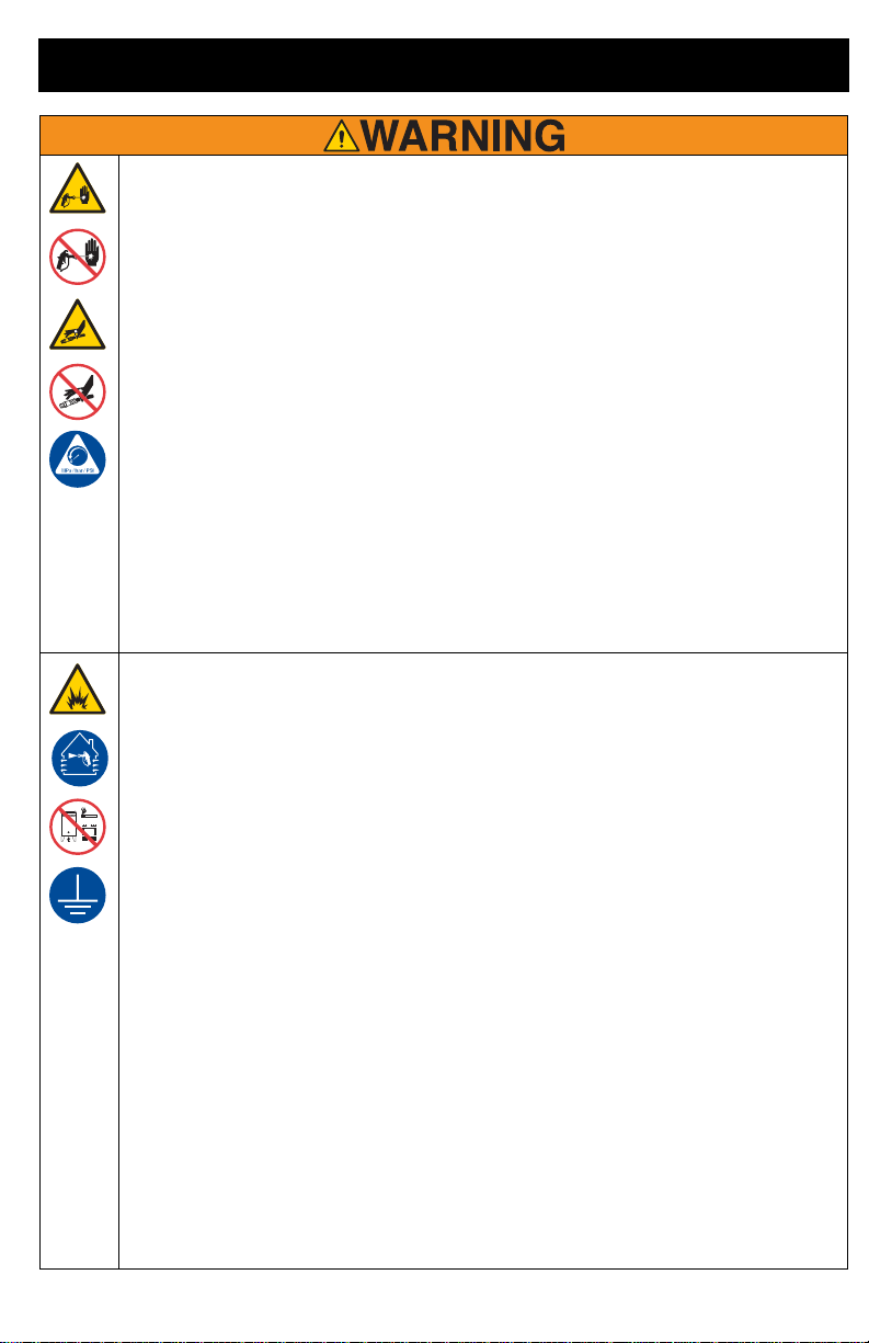
SKIN INJECTION HAZARD
High-pressure spray is able to inject toxins into the body and cause serious bodily injury. In the
event that injection occurs, get immediate surgical treatment.
•Do not aim the gun at, or spray any person or animal.
•Keep hands and other body parts away from the discharge. For example, do not try to stop
leaks with any part of the body.
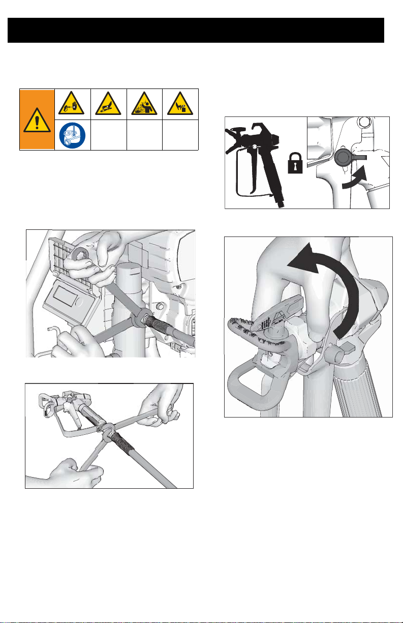
•Always use the nozzle tip guard. Do not spray without nozzle tip guard in place.
•Use Graco nozzle tips.
•Use caution when cleaning and changing nozzle tips. In the case where the nozzle tip clogs
while spraying, follow the Pressure Relief Procedure for turning off the unit and relieving
the pressure before removing the nozzle tip to clean.
•Equipment maintains pressure after power is shut off. Do not leave the equipment
energized or under pressure while unattended. Follow the Pressure Relief Procedure
when the equipment is unattended or not in use, and before servicing, cleaning, or
removing parts.
•Check hoses and parts for signs of damage. Replace any damaged hoses or parts.
•This system is capable of producing 3300 psi. Use Graco replacement parts or accessories
that are rated a minimum of 3300 psi.
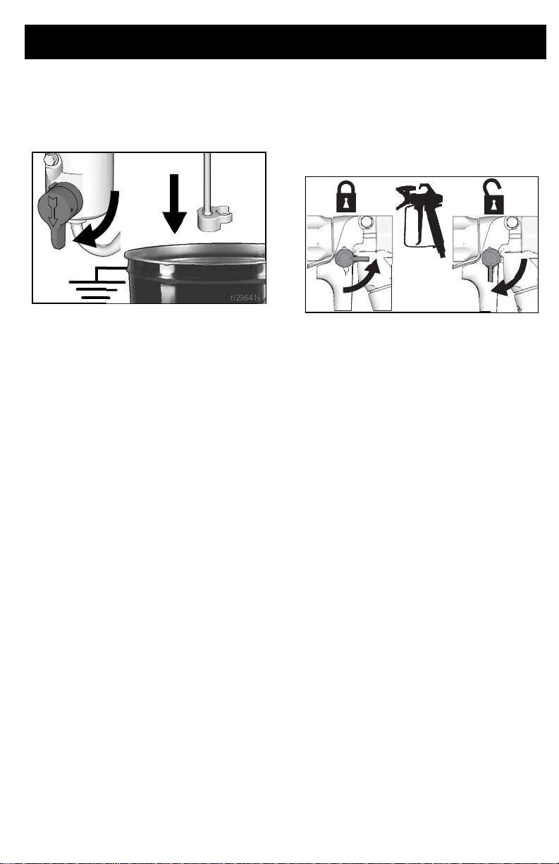
•Always engage the trigger lock when not spraying. Verify the trigger lock is functioning
properly.
•Verify that all connections are secure before operating the unit.
•Know how to stop the unit and bleed pressure quickly. Be thoroughly familiar with the
controls.
FIRE AND EXPLOSION HAZARD
Flammable fumes, such as solvent and paint fumes, in work area can ignite or explode. To help
prevent fire and explosion:
•Do not spray flammable or combustible materials near an open flame or sources of ignition
such as cigarettes, motors, and electrical equipment.
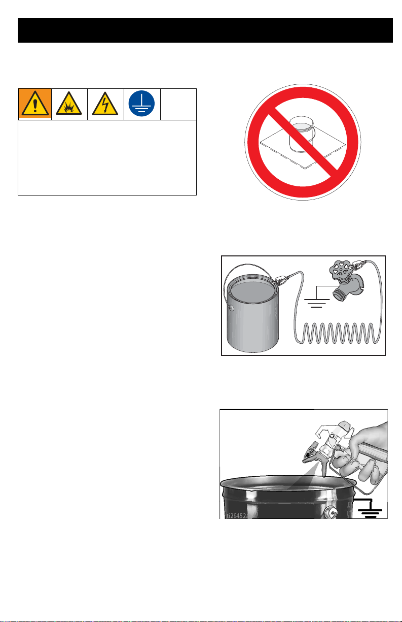
•Paint or solvent flowing through the equipment is able to result in static electricity. Static
electricity creates a risk of fire or explosion in the presence of paint or solvent fumes. All
parts of the spray system, including the pump, hose assembly, spray gun, and objects in
and around the spray area shall be properly grounded to protect against static discharge
and sparks. Use Graco conductive or grounded high-pressure airless paint sprayer hoses.
•Verify that all containers and collection systems are grounded to prevent static discharge.
Do not use pail liners unless they are antistatic or conductive.
•Connect to a grounded outlet and use grounded extensions cords. Do not use a 3-to-2
adapter.
•Do not use a paint or a solvent containing halogenated hydrocarbons.
•Do not spray flammable or combustible liquids in a confined area.
•Keep spray area well-ventilated. Keep a good supply of fresh air moving through the area.
•Sprayer generates sparks. Keep pump assembly in a well ventilated area at least 20 feet
(6.1 m) from the spray area when spraying, flushing, cleaning, or servicing. Do not spray
pump assembly.
•Do not smoke in the spray area or spray where sparks or flame is present.
•Do not operate light switches, engines, or similar spark producing products in the spray
area.
•Keep area clean and free of paint or solvent containers, rags, and other flammable
materials.
•Know the contents of the paints and solvents being sprayed. Read all Material Safety Data
Sheets (MSDS) and container labels provided with the paints and solvents. Follow the
paint and solvents manufacturer’s safety instructions.
•Fire extinguisher equipment shall be present and working.
3

Warnings
EQUIPMENT MISUSE HAZARD
Misuse can cause death or serious injury.
•Always wear appropriate gloves, eye protection, and a respirator or mask when painting.
•Do not operate or spray near children. Keep children away from equipment at all times.
•Do not overreach or stand on an unstable support. Keep effective footing and balance at
all times.
•Stay alert and watch what you are doing.
•Do not operate the unit when fatigued or under the influence of drugs or alcohol.
•Do not kink or over-bend the hose.
•Do not expose the hose to temperatures or to pressures in excess of those specified by
Graco.
•Do not use the hose as a strength member to pull or lift the equipment.
•Do not spray with a hose shorter than 25 feet.
•Do not alter or modify equipment. Alterations or modifications may void agency approvals
and create safety hazards.
•
Make sure all equipment is rated and approved for the environment in which you are using it.
ELECTRIC SHOCK HAZARD
This equipment must be grounded.Improper grounding, setup, or usage of the system can
cause electric shock.
•Turn off and disconnect power cord before servicing equipment.
•Connect only to grounded electrical outlets.
•Use only 3-wire extension cords.
•Ensure ground prongs are intact on power and extension cords.
•Do not expose to rain. Store indoors.
PRESSURIZED ALUMINUM PARTS HAZARD
Use of fluids that are incompatible with aluminum in pressurized equipment can cause serious
chemical reaction and equipment rupture. Failure to follow this warning can result in death,
serious injury, or property damage.
•Do not use 1,1,1-trichloroethane, methylene chloride, other halogenated hydrocarbon
solvents or fluids containing such solvents.
•Do not use chlorine bleach.
•Many other fluids may contain chemicals that can react with aluminum. Contact your
material supplier for compatibility.
4

Warnings
MOVING PARTS HAZARD
Moving parts can pinch, cut, or amputate fingers and other body parts.
•Keep clear of moving parts.
•Do not operate equipment with protective guards or covers removed.
•Pressurized equipment can start without warning. Before checking, moving, or servicing
equipment, follow the Pressure Relief Procedure and disconnect all power sources.
TOXIC FLUID OR FUMES HAZARD
Toxic fluids or fumes can cause serious injury or death if splashed in the eyes or on skin,
inhaled, or swallowed.
•Read MSDSs to know the specific hazards of the fluids you are using.
•Store hazardous fluid in approved containers, and dispose of it according to applicable
guidelines.
PERSONAL PROTECTIVE EQUIPMENT
Wear appropriate protective equipment when in the work area to help prevent serious injury,
including eye injury, hearing loss, inhalation of toxic fumes, and burns. This protective
equipment includes but is not limited to:
•Protective eyewear, and hearing protection.
•Respirators, protective clothing, and gloves as recommended by the fluid and solvent
manufacturer.
CALIFORNIA PROPOSITION 65
This product contains a chemical known to the State of California to cause cancer, birth defects
or other reproductive harm. Wash hands after handling.
5

Component Identification
Hi-Boy Models
B
N
M
U
P
D
K
T
R
S
J
A
L
F
GH
C
A ON/OFF Switch
B Pressure Control
C Two-Finger Trigger Conversion Kit
D Prime Valve
F Tip Guard
G Spray Tip
HGun
J Airless Hose
K Power Cord
L Trigger Lock
M Drain Tube
N Fluid Intake
PPump
R Fluid Outlet
SFilter
T Finger Guard / TSO Fill Point
U Pail Hook
Model/Serial Tag (Not shown, located
on bottom of unit.)
6

Grounding
Grounding
This sprayer includes a ground wire with an
appropriate ground contact.
The plug must be plugged into an outlet that
is properly installed and grounded in
accordance with all local codes and
ordinances.
Do not modify the plug provided; if it does not
fit the outlet, have the proper outlet installed
by a qualified electrician.
Power Requirements
•120V units require 100-120 VAC, 50/60
Hz, 13A, 1 phase.
Extension Cords
Use an extension cord with an undamaged
ground contact. If an extension cord is
necessary, use a 3-wire, 12 AWG (2.5 mm2)
minimum.
NOTE: Smaller gauge or longer extension
cords may reduce sprayer performance.
Pails
Solvent and oil-based fluids: follow local
code. Use only conductive metal pails,
placed on a grounded surface such as
concrete.
Do not place pail on a non-conductive surface
such as paper or cardboard which interrupts
grounding continuity.
Always ground a metal pail: connect a
ground wire to the pail. Clamp one end to the
pail and the other end to a true earth ground
such as a water pipe.
To maintain ground continuity when
sprayer is flushed or pressure is relieved:
hold metal part of spray gun firmly to the side
of a grounded metal pail then trigger the gun.
The equipment must be grounded to
reduce the risk of static sparking and
electric shock. An electric or static spark
can cause fumes to ignite or explode. An
improper ground can cause electric shock.
A good ground provides an escape wire for
the electric current.
7

Pressure Relief Procedure
Follow the Pressure Relief
Procedure whenever you see this
symbol.
1. Turn the ON/OFF switch to OFF
position. Wait 7 seconds for power to
dissipate.
2. Engage the trigger lock.
3. Turn pressure control to lowest setting.
Disengage the trigger lock.
4. Hold a metal part of the gun firmly to a
grounded metal pail. Trigger the gun to
relieve pressure.
5. Engage the trigger lock.
This equipment stays pressurized until
pressure is manually relieved. To help
prevent serious injury from pressurized
fluid, such as skin injection, splashed fluid
and moving parts, follow the Pressure
Relief Procedure whenever sprayer is
stopped and before sprayer is cleaned or
checked, and before equipment is
serviced.
8

Pressure Relief Procedure
6. Put drain tube in a pail. Turn prime valve
down. Leave prime valve in down (drain)
position until you are ready to spray
again.
7. If you suspect the spray tip or hose is
clogged or that pressure has not been
fully relieved:
a. VERY SLOWLY loosen the tip
guard retaining nut or the hose end
coupling to relieve pressure
gradually.
b. Loosen the nut or coupling
completely.
c. Clear hose or tip obstruction.
Trigger Lock
Always engage the trigger lock when sprayer
is stopped to prevent the gun from being
triggered accidentally by hand or if dropped
or bumped.
ti29641a
9

Setup
Setup
When unpacking sprayer for the first time or
after long term storage perform setup
procedure. When first setup is performed
remove shipping plug from fluid outlet.
1. Connect airless hose to fluid outlet. Use
wrenches to tighten securely.
2. Connect other end of hose to gun.
3. Use wrenches to tighten securely.
4. Engage trigger lock.
5. Remove tip guard.
10

Setup
6. When unpacking sprayer for the first
time remove packaging materials from
inlet strainer. After long term storage
check inlet strainer for clogs and debris.
7. Fill throat packing nut with TSO to
prevent premature packing wear. Do this
daily or each time you spray.
a. Place the TSO bottle nozzle into the
top center opening in the grill at the
front of the sprayer.
b. Squeeze bottle to dispense enough
TSO to fill the space between the
pump rod and packing nut seal.
8. Make certain ON/OFF switch is OFF.
9. Plug power supply cord into a properly
grounded electrical outlet.
11

Setup
10. Turn prime valve down.
11. Place fluid intake with drain tube in
grounded metal pail partially filled with
flushing fluid. See Grounding
12. Turn pressure control to lowest setting.
13. Turn ON/OFF switch to ON position.
14. Increase pressure 1/2 turn to start motor.
Allow fluid to flush through sprayer for
one minute.
15. Turn prime valve horizontal. Disengage
trigger lock.
16. Hold a metal part of the gun firmly to a
grounded metal pail. Trigger gun and
flush until clean.
17. Turn ON/OFF switch to OFF position.
18. Engage trigger lock.
19. After flushing storage fluid out of the
sprayer empty pail. Replace fluid intake
with drain tube in grounded metal pail
partially filled with flushing fluid. Use
water to flush water-based paint or
mineral spirits to flush oil-based paint.
20. Turn ON/OFF switch to ON position.
21. Turn prime valve horizontal. Disengage
trigger lock.
22. Hold a metal part of the gun firmly to a
grounded metal pail. Trigger gun and
flush for one minute.
23. Turn ON/OFF switch to OFF position.
24. Engage trigger lock.
25. Sprayer is now ready to start up and
spray.
NOTE: New sprayers are shipped with
storage fluid that must be flushed out with
mineral spirits prior to using the sprayer.
Check flushing fluid for compatibility with
material that is to be sprayed. A secondary
flush with a compatible fluid may be
necessary. Use water for latex paint, or
mineral spirits for oil-based paint.
ti29641a
12

Startup
Startup
1. Perform Pressure Relief Procedure
2. Turn pressure control to lowest
pressure.
3. Place fluid intake in paint pail. Place
drain tube in waste pail.
4. Turn ON/OFF switch to ON position.
5. Turn pressure control 1/2 turn to start
motor. Allow paint to circulate through
sprayer until paint flows out the drain
tube.
6. Turn prime valve horizontal. Disengage
trigger lock.
15 s
13

Startup
7. Hold gun against grounded metal waste
pail. Trigger gun until paint appears.
8. Move gun to paint pail and trigger for 20
seconds. Release trigger and allow
sprayer to build pressure. Engage
trigger lock.
9. Inspect for leaks. If leaks occur, perform
Pressure Relief Procedure
then tighten all fittings and repeat
Startup procedure. If there are no leaks
continue with the next step.
10. Screw tip assembly onto gun and
tighten. See Spray Tip Installation
For gun assembly instructions,
see separate gun manual.
1m
20s
High-pressure spray is able to inject toxins
into the body and cause serious bodily
injury. Do not stop leaks with hand or rag.
14

Operation
Operation
Spray Tip Installation
1. Perform Pressure Relief Procedure
2. Use spray tip to insert seal into tip
guard. Insert Spray Tip.
3. Screw assembly onto gun. Tighten.
Spray
1. Spray test pattern. Adjust pressure to
eliminate heavy edges.
2. Use smaller tip size if pressure
adjustment cannot eliminate heavy
edges.
3. Hold gun perpendicular, 10-12 in. (25-30
cm) from surface. Spray back and forth;
overlap by 50%.
4. Trigger gun after moving. Release
trigger before stopping. For additional
spraying information, see separate gun
manual.
0 0
To avoid serious injury from skin injection
do not put your hand in front of the spray tip
when installing or removing the spray tip
and tip guard.
15

Operation
Clear Tip Clog
In the event that particles or debris clog the
spray tip, this sprayer is designed with a
reversible spray tip that quickly and easily
clears the particles without disassembling the
sprayer.
1. Engage trigger lock. Rotate spray tip to
unclog position. Disengage trigger lock.
Trigger gun at waste area to clear clog.
NOTE: If spray tip is difficult to rotate when
turning to the unclog position, perform
Pressure Relief Procedure, then
turn Prime/Spray valve to spray position and
repeat step 1.
2. Engage trigger lock. Rotate spray tip
back to spray position. Disengage trig-
ger lock and continue spraying.
1
2
16

Operation
Digital Display
Some models are equipped with a digital
display. This section explains how to use this
feature.
Pressure Display
1. Perform Pressure Relief
Procedure
2. Plug sprayer into grounded outlet. Turn
ON/OFF switch to ON position.
3. The pressure is displayed. Dashes
indicate pressure is less than 200 psi (14
bar, 1.4 MPa).
4. Press and release display button to
display total running hours.
5. Press and hold display button to change
pressure units (psi, bar, or MPa).
Stored Data Display
1. Turn ON/OFF switch to OFF position.
2. To enter Stored Data Mode, press and
hold display button and turn ON/OFF
switch to ON position.
17

Operation
3. Sprayer model number is displayed
followed by Data Point 1 which is the unit
power on time in hours.
4. Press display button again to display
Data Point 2. Motor run time in hours is
displayed.
5. Press display button again to display
Data Point 3. This will be the last error
code.
6. To erase last error code, press and hold
display button.
7. Press display button again to display
Data Point 4. The software revision is
displayed.
8. Press display button again to return to
Data Point 1.
9. Turn ON/OFF switch to OFF position to
exit Stored Data.
18

Operation
Cleanup
1. Perform Pressure Relief Procedure
2. Remove tip guard and Spray Tip. For
additional information, see separate gun
manual.
3. Remove fluid intake and drain tube from
paint, wipe excess paint off outside.
4. Place fluid intake in flushing fluid. Use
water for water base paint and mineral
spirits for oil-based paint. Place drain
tube in waste pail.
5. Turn prime valve horizontal.
6. Increase pressure 1/2 turn to start motor.
Hold gun against paint pail. Disengage
trigger lock. Trigger gun and increase
pressure until the pump runs steady and
flushing fluid appears.
19

Operation
7. Stop triggering gun. Move gun to waste
pail, hold gun against pail, trigger gun to
thoroughly flush system.
8. While continuing to trigger gun, turn
prime valve down. Then, release gun
trigger. Allow flushing fluid to circulate
until fluid comes out of drain tube clear.
9. Raise fluid intake above flushing fluid.
10. Turn prime valve horizontal. Trigger gun
into flushing pail to purge fluid from hose.
20
Table of contents
Other Lemmer Paint Sprayer manuals