Lemmer DC3200 User manual

OWNER'S MANUAL
DC-3200
Do not use this equipment before
reading this manual!
DC-3200
WARNING..Read all instructions carefully before assembling components and operating sprayer. Incorrect procedure could result in damage to the
unit, severe personal injury and/or property damage. When spraying flammable materials, sprayer must be placed at least 20 feet from target in a well-
ventilated area. Vapours can be ignited by static discharge or electrical sparks and result in severe personal injury. LEMMER airless sprayers generate
high fluid pressure. Improper use could result in an injection injury.
CALGARY • TORONTO • MONTRÉAL
NOTE: This manual contains important
warnings and instructions. Please
read and retain for reference.

English English
2
Important Safety Information
Read all safety information before operating the
equipment. Save these instructions.
Indicates a hazardous situation which, if not avoided,
could result in death or serious injury.
To reduce the risks of re or explosion, electrical shock
and the injury to persons, read and understand all
instructions included in this manual. Be familiar with the
controls and proper usage of the equipment.
Grounding Instructions
This product must be grounded. In the event of an electrical short circuit,
grounding reduces the risk of electric shock by providing an escape wire
for the electric current. This product is equipped with a cord having a
grounding wire with an appropriate grounding plug. The plug must
be plugged into an outlet that is properly installed and grounded in
accordance with all local codes and ordinances.
WARNING - Improper installation of the grounding plug
can result in a risk of electric shock.
If repair or replacement of the cord or plug is necessary, do not connect
the green grounding wire to either at blade terminal. The wire with
insulation having a green outer surface with or without yellow stripes is
the grounding wire and must be connected to the grounding pin.
Check with a qualied electrician or serviceman if the grounding
instructions are not completely understood, or if you are in doubt as
to whether the product is properly grounded. Do not modify the plug
provided. If the plug will not t the outlet, have the proper outlet
installed by a qualied electrician.
This product is for use on a nominal 120 volt circuit and has a grounding
plug that looks like the plug illustrated below. Make sure that the product
is connected to an outlet having the same conguration as the plug. No
adapter should be used with this product.
Grounded Outlet
Grounding Pin
Cover for grounded outlet box
IMPORTANT: When the sprayer is used with a generator
or uncontrolled line voltage, the use of “Line Surge
Protector” is recommended.
WARNING: EXPLOSION OR FIRE
Solvent and paint fumes can explode or ignite. Property
damage and/or severe injury can occur.
PREVENTION:
• Do not spray ammable or combustible materials near an open
ame, pilot lights or sources of ignition such as hot objects,
cigarettes, motors, electrical equipment and electrical appliances.
Avoid creating sparks from connecting and disconnecting power
cords.
• Use extreme caution when using materials with a ashpoint
below 100ºF (38ºC). Flashpoint is the temperature that a uid can
produce enough vapors to ignite.
• Paint or solvent owing through the equipment is able to result
in static electricity. Static electricity creates a risk of re or
explosion in the presence of paint or solvent fumes. All parts
of the spray system, including the pump, hose assembly, spray
gun and objects in and around the spray area shall be properly
grounded to protect against static discharge and sparks. Use only
conductive or grounded high-pressure airless paint sprayer hoses
specied by the manufacturer.
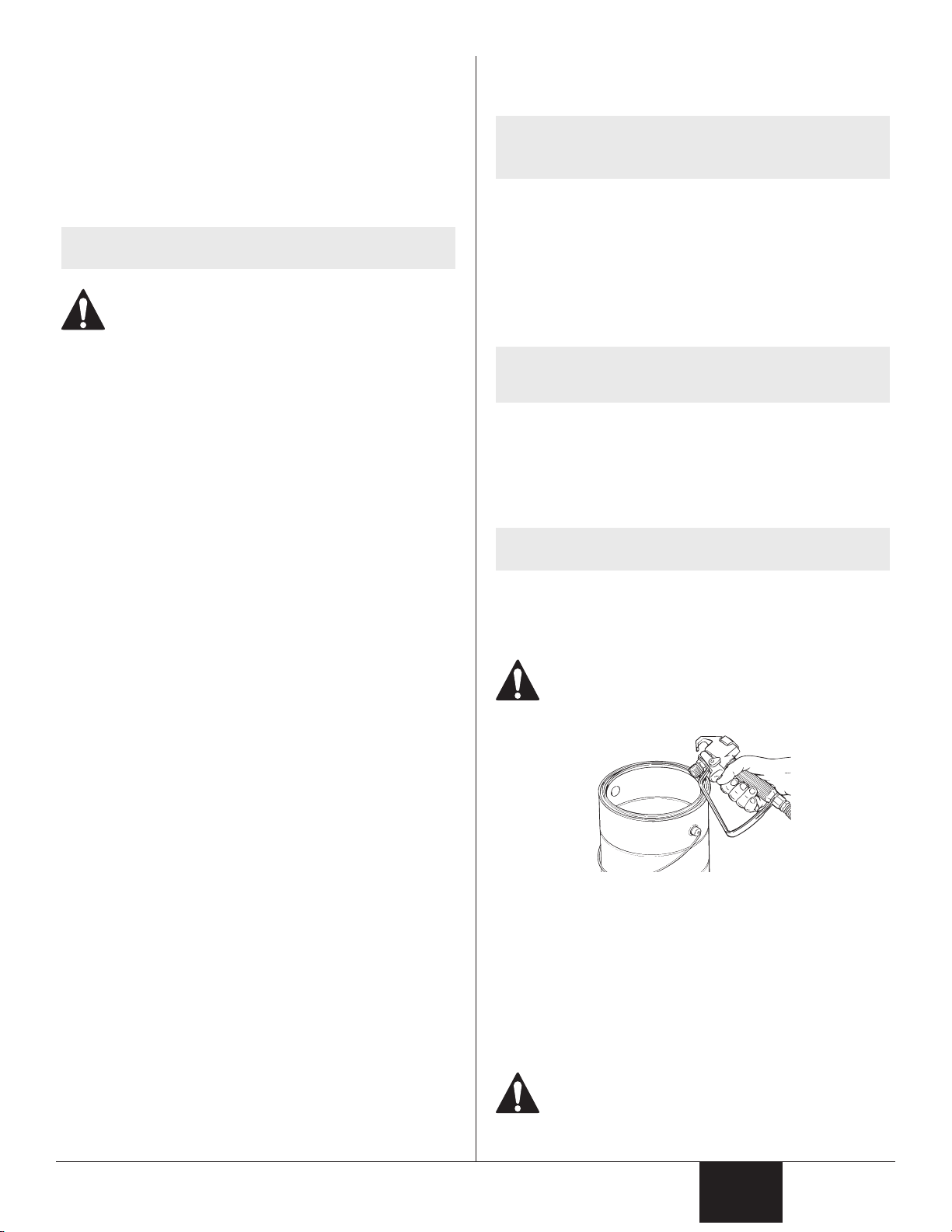
• Verify that all containers and collection systems are grounded to
prevent static discharge.
• Connect to a grounded outlet and use grounded extension cords
(electric models only). Do not use a 3 to 2 adapter.
• Do not use a paint or solvent containing halogenated
hydrocarbons. Such as chlorine, bleach mildewcide, methylene
chloride and trichloroethane. They are not compatible with
aluminum. Contact the coating supplier about compatibility of
material with aluminum.
• Keep spray area well ventilated. Keep a good supply of fresh air
moving through the area to keep the air within the spray area free
from accumulation of ammable vapors. Keep pump assembly in
well ventilated area. Do not spray pump assembly.
• Do not smoke in the spray area.
• Do not operate light switches, engines, or similar spark producing
products in the spray area.
• Keep area clean and free of paint or solvent containers, rags, and
other ammable materials.
• Know the contents of the paint and solvents being sprayed.
Read all Material Safety Data Sheets (MSDS) and container labels
provided with the paints and solvents. Follow the paint and
solvent manufacture’s safety instructions.
• Place pump at least 25 feet (7.62 meters) from the spray object in
a well ventilated area (add more hose if necessary). Flammable
vapors are often heavier than air. Floor area must be extremely
well ventilated. The pump contains arcing parts that emit sparks
and can ignite vapors.
• Plastic can cause static sparks. Never hang plastic to enclose spray
area. Do not use plastic drop cloths when spraying ammable
material.
• Fire extinguisher equipment shall be present and working.
WARNING: INJECTION INJURY
A high pressure paint stream produced by this equipment
can pierce the skin and underlying tissues, leading to
serious injury and possible amputation. See a physician
immediately.
PREVENTION:
• Do not aim the gun at, or spray any person or animal.
• Keep hands and other body parts away from the discharge. For
example, do not try to stop leaks with any part of the body.
• NEVER put your hand in front of the gun. Gloves will not provide
protection against an injection injury.
• ALWAYS keep the tip guard in place while spraying. The tip guard
provides some protection but is mainly a warning device.
• Only use a nozzle tip specied by the manufacturer.
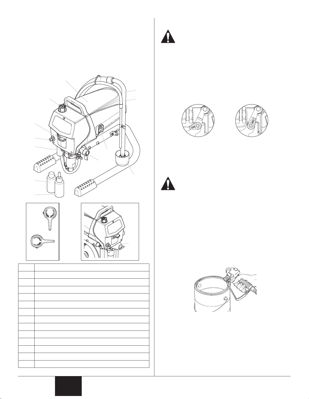
• Use caution when cleaning and changing nozzle tips. In the
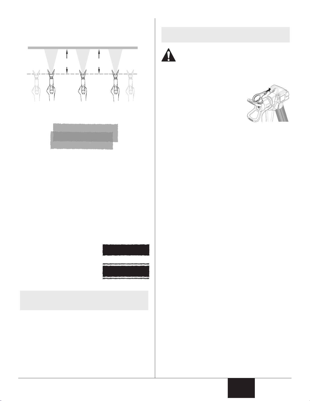
case where the nozzle tip clogs while spraying, ALWAYS lock
gun trigger, shut pump o, and release all pressure before
servicing, cleaning tip or guard, or changing tip. Pressure will
not be released by turning o the motor. The PRIME/SPRAY
valve or pressure bleed valve must be turned to their appropriate
positions to relieve system pressure. Refer to PRESSURE RELIEF
PROCEDURE described in the pump manual.
• Do not leave the unit energized or under pressure while
unattended. When the unit is not in use, turn o the unit and
relieve the pressure in accordance with the manufacturer’s
instructions.
• High-pressure spray is able to inject toxins into the body and
cause serious bodily injury. In the event that injection occurs,
seek medical attention immediately.
• Check hoses and parts for signs of damage, a leak can inject
material into the skin. Inspect hose before each use. Replace any

English English
3
Important Safety Information
damaged hoses or parts. Only use LEMMER original-high-pressure
hoses in order to ensure functionality, safety and durability.
• This system is capable of producing 3000 PSI / 207 Bar. Only
use replacement parts or accessories that are specied by the
manufacturer and that are rated a minimum of 3000 PSI. This
includes spray tips, nozzle guards, guns, extensions, ttings, and
hose.
• Always engage the trigger lock when not spraying. Verify the
trigger lock is functioning properly.
• Verify that all connections are secure before operating the unit.
• Know how to stop the unit and bleed pressure quickly. Be
thoroughly familiar with the controls. Pressure will not be
released by turning o the motor. The PRIME/SPRAY valve
or pressure bleed valve must be turned to their appropriate
positions to relieve system pressure. Refer to PRESSURE RELIEF
PROCEDURE described in the pump manual.
• Always remove the spray tip before ushing or cleaning the
system.
NOTE TO PHYSICIAN:
Injection into the skin is a traumatic injury which can lead to
possible amputation. It is important to treat the injury as soon as
possible. DO NOT delay treatment to research toxicity. Toxicity
is a concern with some coatings injected directly into the blood
stream. Consultation with a plastic surgeon or reconstructive hand
surgeon may be advisable.
WARNING: HAZARDOUS VAPORS
Paints, solvents, insecticides, and other materials can
be harmful if inhaled or come in contact with the body.
Vapors can cause severe nausea, fainting, or poisoning.
PREVENTION:
• Use a respirator or mask if vapors can be inhaled. Read all
instructions supplied with the mask to be sure it will provide the
necessary protection.
• Wear protective eyewear.
• Wear protective clothing as required by coating manufacturer.
WARNING: GENERAL
Can cause severe injury or property damage.
PREVENTION:
• Always wear appropriate gloves, eye protection, clothing and a
respirator or mask when painting.
• Do not operate or spray near children. Keep children away from
equipment at all times.
• Do not overreach or stand on an unstable support. Keep eective
footing and balance at all times.
• Stay alert and watch what you are doing.
• Do not operate the unit when fatigued or under the inuence of
drugs or alcohol.
• Do not kink or over-bend the hose. Airless hose can develop leaks
from wear, kinking and abuse. A leak can inject material into the
skin.
• Do not expose the hose to temperatures or pressures in excess of
those specied by manufacturer.
• Do not use the hose as a strength member to pull or lift the
equipment.
• Use lowest possible pressure to ush equipment.
• Follow all appropriate local, state and national codes governing
ventilation, re prevention and operation.
• The United States Government Safety Standards have been
adopted under the Occupational Safety and Health Act (OSHA).
These standards, particularly part 1910 of the General Standards
and part 1926 of the Construction Standards should be consulted.
• Before each use, check all hoses for cuts, leaks, abrasion or
bulging of cover. Check for damage or movement of couplings.
Immediately replace hose if any of those conditions exist. Never
repair a paint hose. Replace with a conductive high-pressure
hose.
• Do not spray outdoors on windy days.
• Always unplug cord from outlet before working on equipment
(electric models only).
Specications
Gallons per minute (GPM) 0.47 (1.8 LPM)
Maximum tip size 0.021”
Maximum pressure 3000 PSI (20.7 MPa)
Power 0.75 HP DC motor, 120V, 60 Hz
Weight, skid 27 lbs (12.2 kg)
Weight, high rider 50 lbs (22.7 kg)
Maximum hose length 100’ (30.5 m)
Generator requirement 5000 Watt, 20A, sine wave generator,
idle-down feature disabled

English English
4
General Description
This airless sprayer is a precision power tool used for spraying
many types of materials. Read and follow this instruction manual
carefully for proper operating instructions, maintenance, and safety
information.
This pump is available in a stand model ( ) and a cart model
( )
Some of the graphics in this manual may not exactly match your
sprayer and spray gun. All information and instructions given in this
manual applies to all models except where noted.
2
1
6
11
7
10
9*
9*
PRIME
SPRAY
8
3
4
5
12
13
k
p
Item Description
1Motor
2Pressure control knob
3Oil cup
4Outlet tting
5Filter
6Siphon tube
7Return hose
8ON/OFF switch
9PRIME/SPRAY valve
10 Drip cup (stand model only)
11 Pail bracket (cart model only)
12 Liquid Shield™ (4 oz.)
13 Piston Lube™ (4 oz.)
Operation
This equipment produces a fluid stream at extremely
high pressure. Read and understand the warnings
in the Safety Precautions section at the front of this
manual before operating this equipment.
IMPORTANT: The vents in the bottom and rear of the motor
shroud are designed to keep the motor from getting excessively
hot during operation. Make sure the vents in the bottom and
rear of the motor shroud are not covered or obstructed.
Locking the Spray Gun
1. To lock the trigger, rotate the trigger lock forward until it
stops.
2. To unlock the trigger, rotate the trigger lock backwards until it
is vertical.
Trigger locked (gun
will not spray) Trigger unlocked
(gun will spray)
Pressure Relief Procedure
Be sure to follow the Pressure Relief Procedure when
shutting down the sprayer for any purpose, including
servicing or adjusting any part of the spray system,
changing or cleaning spray tips, or preparing for
cleanup.
1. Lock the gun by turning the gun trigger lock to the locked
position.
2. Move the PRIME/SPRAY valve down to the PRIME position.
3. Turn o the sprayer by moving the ON/OFF switch to the OFF
position.
4. Set the pressure to minimum by turning the pressure control
knob fully counterclockwise.
5. Unlock the gun by turning the gun trigger lock to the
unlocked position.
6. Hold the metal part of the gun rmly to the side of a metal
container to ground the gun and avoid a build up of static
electricity.
7. Trigger the gun to remove any pressure that may still be in the
hose.
8. Lock the gun by turning the gun trigger lock to the locked
position.
L045-014
L045-016

English English
5
Setup
Perform the following procedure before plugging in the power cord
of an electric unit.
1. Ensure that the siphon tube and the return hose are attached
and secure.
2. Using a wrench, attach a minimum of 50’ of 1/4” airless spray
hose to the outlet tting on the sprayer. Tighten securely.
3. Attach an airless spray gun to the spray hose. Using two
wrenches (one on the gun and one on the hose), tighten
securely.
NOTE: Do not attach the tip to the spray gun yet. Remove
the tip if it is already attached.
Make sure all airless hoses and spray guns are
electrically grounded and rated at or above the
maximum operating pressure range of the airless
sprayer.
4. Make sure the pressure control knob is turned fully
counterclockwise to its lowest pressure setting.
5. Make sure the ON/OFF switch is in its OFF position.
6. Fill the oil cup with approximately one tablespoon of Piston
Lube™
IMPORTANT: Never operate unit for more than ten seconds
without fluid. Operating this unit without fluid will cause
unnecessary wear to the packings.
7. Make sure the electrical service is 120V, 15 amp minimum.
8. Plug the power cord into a properly grounded outlet at least
25’ from the spray area.
IMPORTANT: Always use a minimum 12 gauge, three-wire
extension cord with a grounded plug. Never remove the third
prong or use an adapter.
Preparing a New Sprayer
If this sprayer is new, it is shipped with test uid in the uid section to
prevent corrosion during shipment and storage. This uid must be
thoroughly cleaned out of the system with mineral spirits before you
begin spraying.
IMPORTANT: Always keep the trigger lock on the spray gun in
the locked position while preparing the system.
1. Place the siphon tube into a container of mineral spirits.
2. Place the return hose into a metal waste container.
3. Set the pressure to minimum by turning the pressure control
knob fully counterclockwise.
4. Move the PRIME/SPRAY valve down to the PRIME position.
5. Turn on the sprayer by moving the ON/OFF switch to the ON
position.
6. Allow the sprayer to run for 15–30 seconds to ush the
test uid out through the return hose and into the waste
container.
7. Turn o the sprayer by moving the ON/OFF switch to the OFF
position.
Preparing to Paint
Before painting, it is important to make sure that the uid in the
system is compatible with the paint that is going to be used.
NOTE: Incompatible uids and paint may cause the valves
to become stuck closed, which would require
disassembly and cleaning of the sprayer’s uid
section.
IMPORTANT: Always keep the trigger lock on the spray gun in
the locked position while preparing the system.
1. Place the siphon tube into a container of the appropriate
solvent. Examples of the appropriate solvent are water for
latex paint or mineral spirits for oil-based paints.
2. Place the return hose into a metal waste container.
3. Set the pressure to minimum by turning the pressure control
knob fully counterclockwise.
4. Move the PRIME/SPRAY valve down to the PRIME position.
NOTE: Hold the return hose in the waste container when
moving the PRIME/SPRAY valve to PRIME in case the
sprayer is pressurized.
5. Turn on the sprayer by moving the ON/OFF switch to the ON
position.
6. Allow the sprayer to run for 15–30 seconds to ush the old
solvent out through the return hose and into the metal waste
container.
7. Turn o the sprayer by moving the ON/OFF switch to the OFF
position.
NOTE: Make sure that the spray gun does not have a tip or
tip guard installed.
8. Move the PRIME/SPRAY valve up to the SPRAY position.
9. Turn on the sprayer.
10. Unlock the gun by turning the gun trigger lock to the
unlocked position.
Ground the gun by holding it against the edge of the
metal container while flushing. Failure to do so may
lead to a static electric discharge, which may cause a
fire.
11. Trigger the gun into the metal waste container until the old
solvent is gone and fresh solvent is coming out of the gun.
12. Lock the gun by turning the gun trigger lock to the locked
position.
13. Set down the gun and increase the pressure by turning the
pressure control knob slowly clockwise.
14. Check the entire system for leaks. If leaks occur, follow the
“Pressure Relief Procedure” in this manual before tightening
any ttings or hoses.
15. Follow the “Pressure Relief Procedure” in this manual before
changing from solvent to paint.
Be sure to follow the “Pressure Relief Procedure” when
shutting down the sprayer for any purpose, including
servicing or adjusting any part of the spray system,
changing or cleaning spray tips, or preparing for
cleanup.

English English
6
Painting
1. Place the siphon tube into a container of paint.
2. Place the return hose into a metal waste container.
3. Set the pressure to minimum by turning the pressure control
knob fully counterclockwise.
4. Move the PRIME/SPRAY valve down to the PRIME position.
5. Turn on the sprayer by moving the ON/OFF switch to the ON
position.
6. Allow the sprayer to run until paint is coming through the
return hose into the metal waste container.
7. Turn o the sprayer by moving the ON/OFF switch to the OFF
position.
8. Remove the return hose from the waste container and place it
in its operating position into the container of paint.
9. Move the PRIME/SPRAY valve up to the SPRAY position.
10. Turn on the sprayer.
11. Unlock the gun by turning the gun trigger lock to the
unlocked position.
Ground the gun by holding it against the edge of the
metal container while flushing. Failure to do so may
lead to a static electric discharge, which may cause a
fire.
12. Trigger the gun into the metal waste container until all air and
solvent is ushed from the spray hose and paint is owing
freely from the gun.
13. Lock the gun by turning the gun trigger lock to the locked
position.
14. Turn o the sprayer.
15. Attach tip guard and tip to the gun as instructed by the tip
guard or tip manuals.
POSSIBLE INJECTION HAZARD. Do not spray without
the tip guard in place. Never trigger the gun unless
the tip is in either the spray or the unclog position.
Always engage the gun trigger lock before removing,
replacing or cleaning tip.
16. Turn on the sprayer.
17. Increase the pressure by turning the pressure control knob
slowly clockwise and test the spray pattern on a piece of
cardboard. Adjust the pressure control knob until the
spray from the gun is completely atomized. Try to keep the
pressure control knob at the lowest setting that maintains
good atomization.
NOTE: Turning the pressure up higher than needed to
atomize the paint will cause premature tip wear and
additional overspray.
Spraying
POSSIBLE INJECTION HAZARD. Do not spray without
the tip guard in place. Never trigger the gun unless
the tip is in either the spray or the unclog position.
Always engage the gun trigger lock before removing,
replacing, or cleaning tip.
Spraying Technique
The key to a good paint job is an even coating over the entire surface.
This is done by using even strokes. Keep your arm moving at a
constant speed and keep the spray gun at a constant distance from
the surface. The best spraying distance is 10 to 12 inches between
the spray tip and the surface.
Keep stroke smooth and at an even speed.
Even coat throughout
Approximately
10 to 12 inches
Keep the spray gun at right angles to the surface. This means moving
your entire arm back and forth rather than just exing your wrist.
Heavy Coat
Do not ex wrist while spraying.
Light Coat Light Coat
Keep the spray gun perpendicular to the surface, otherwise one end
of the pattern will be thicker than the other.
Approximately
10 to 12 inches
Right way
Wrong way

English English
7
The spray gun should be triggered by turning it on and o with each
stroke. This will save paint and avoid paint buildup at the end of the
stroke. Do not trigger the gun during the middle of a stroke. This will
result in an uneven spray and splotchy coverage.
Proper way to trigger the spray gun
Approximately
10 to 12 inches
Keep stroke
even
Start stroke End strokePull trigger Release triggerKeep steady
Overlap each stroke by about 50%. This will ensure an even coating.
50% Overlap
When you stop painting, lock the gun trigger lock, turn the pressure
control knob counterclockwise to its lowest setting and set the
PRIME/SPRAY valve to PRIME. Turn the ON/OFF switch to the OFF
position and unplug the sprayer.
Practice
1. Be sure that the paint hose is free of kinks and clear of objects
with sharp cutting edges.
3. Set the pressure to minimum by turning the pressure control
knob fully counterclockwise.
3. Move the PRIME/SPRAY valve up to its SPRAY position.
4. Turn the pressure control knob clockwise to its highest
setting. The paint hose should stien as paint begins to ow
through it.
5. Unlock the gun trigger lock.
6. Trigger the spray gun to bleed air out of the hose.
Good spray pattern
Paint tailing pattern
7. When paint reaches the spray tip,
spray a test area to check the spray
pattern.
8. Use the lowest pressure setting
necessary to get a good spray
pattern. If the pressure is set too
low, tailing will appear or the paint
will spatter out in gobs rather than
in a ne spray.
NOTE: Turning the pressure up higher than needed to
atomize the paint will cause premature tip wear and
additional overspray.
Clearing the Spray Tip
NOTE: If your spray pattern becomes distorted or stops
completely during spraying, follow these steps.
The flow from the spray tip is at very high pressure.
Contact with any body part may be dangerous. Do not
place finger on gun outlet. Do not point the gun at
any person. Never operate the spray gun without the
proper tip guard.
1. Follow the “Pressure Relief Procedure” found in the Operation
section of this manual.
2. If the tip clogs, rotate the tip
handle 180º until the arrow on the
handle is facing the opposite of
the spray direction and the handle
stops in the reverse position.
3. Trigger the gun once into a waste
container so that the pressure
can blow the clog out. NEVER use
the tip in the reverse position for
more than ONE trigger pull at a time. This procedure can be
repeated until the tip is free of clogging.

English English
8
Cleanup
Special cleanup instructions for use with flammable
solvents:
• Always ush spray gun preferably outside and at least one
hose length from spray pump.
• If collecting ushed solvents in a one gallon metal container,
place it into an empty ve gallon container, then ush
solvents.
• Area must be free of ammable vapors.
• Follow all cleanup instructions.
Always spray at minimum pressure with the gun
nozzle tip removed when using mineral spirits or any
other solvent to clean the sprayer, hose, or gun. Static
electricity buildup may result in a re or explosion in
the presence of ammable vapors.
IMPORTANT: The sprayer, hose, and gun should be cleaned
thoroughly after daily use. Failure to do so permits material to
build up, seriously affecting the performance of the unit.
1. Follow the “Pressure Relief Procedure” found in the Operation
section of this manual.
2. Remove the gun tip and tip guard and clean with a brush
using the appropriate solvent.
3. Place the siphon tube into a container of the appropriate
solvent. Examples of the appropriate solvent are water for
latex paint or mineral spirits for oil-based paints.
4. Place the return hose into a metal waste container.
5. Set the pressure to minimum by turning the pressure control
knob fully counterclockwise.
6. Move the PRIME/SPRAY valve down to its PRIME position.
NOTE: Hold the return hose in the waste container when
moving the PRIME/SPRAY valve to PRIME in case the
sprayer is pressurized.
7. Turn on the sprayer by moving the ON/OFF switch to the ON
position.
8. Allow the solvent to circulate through the unit and ush the
paint out of the return hose into the metal waste container.
9. Turn o the sprayer by moving the ON/OFF switch to the OFF
position.
10. Move the PRIME/SPRAY valve up to its SPRAY position.
11. Turn on the sprayer.
Ground the gun by holding it against the edge of the
metal container while flushing. Failure to do so may
lead to a static electric discharge, which may cause a
fire.
12. Trigger the gun into the metal waste container until the paint
is ushed out of the hose and solvent is coming out of the
gun.
13. Continue to trigger the spray gun into the waste container
until the solvent coming out of the gun is clean.
NOTE: For long-term or cold weather storage, pump
mineral sprits through the entire system.
For short-term storage when using latex paint,
pump water mixed with Liquid Shield through
the entire system (see the Accessories section of this
manual for part number).
14. Follow the “Pressure Relief Procedure” found in the Operation
section of this manual.
15. Loosen and remove the lter housing (1).
16. Turning clockwise, unscrew the lter (2) from the pump
manifold (3).
NOTE: Left-handed threads require turning the lter
clockwise to remove.
17. Make sure the lter seal (4) is in position.
18. Turning counterclockwise, screw the new or cleaned lter into
the pump manifold.
19. Clean the inside of the lter housing using the appropriate
cleaning solution.
20. Slide the lter housing over the lter and thread it into the
pump manifold until secure.
1
3
2
4
21. Unplug the unit and store in a clean, dry area.
IMPORTANT: Do not store the unit under pressure.

English English
9
Maintenance
Before proceeding, follow the “Pressure Relief
Procedure” outlined previously in this manual.
Additionally, follow all other warnings to reduce the
risk of an injection injury, injury from moving parts
or electric shock. Always unplug the sprayer before
servicing!
General Repair and Service Notes
The following tools are needed when repairing this sprayer:
Phillips Screwdriver 3/8” Hex Wrench
Needle Nose Pliers 5/16” Hex Wrench
Adjustable Wrench 1/4” Hex Wrench
Rubber Mallet 3/16” Hex Wrench
Flat-blade Screwdriver 5/32” Hex Wrench
Torque wrench (in.-lbs.) Resistance multi-meter
Pressure gauge
1. Before repairing any part of the sprayer, read the instructions
carefully, including all warnings.
IMPORTANT: Never pull on a wire to disconnect it. Pulling on a
wire could loosen the connector from the wire.
2. Test your repair before regular operation of the sprayer to be
sure that the problem is corrected. If the sprayer does not
operate properly, review the repair procedure to determine if
everything was done correctly. Refer to the Troubleshooting
Charts to help identify other possible problems.
3. Make certain that the service area is well ventilated in case
solvents are used during cleaning. Always wear protective
eyewear while servicing. Additional protective equipment
may be required depending on the type of cleaning solvent.
Always contact the supplier of solvents for recommendations.
Replacing the Motor
NOTE: It is recommended that the following procedure be
performed by an Authorized Service Center.
1. Perform the “Pressure Relief Procedure” and unplug the
sprayer.
2. Loosen and remove the four motor cover screws (1). Remove
the motor cover (2).
NOTE: The ON / OFF switch (3) is housed inside the
motor cover. In order to remove the motor cover
completely, you must disconnect all of the wires at
the rear of the switch. Note the position of the wires
before disconnecting.
3. On the back of the motor (4), disconnect the two wires (black
and red) coming from the circuit board (5). Remove the
ground wire from the motor housing.
4. Slide the motor bae (7) o the rear of the motor.
5. Loosen and remove the four motor mounting screws (8).
6. Pull the motor (4) out of the pump housing (9).
7. With the motor removed, inspect the gears in the pump
housing (9) for damage or excessive wear. Replace the gears,
if necessary.
8. Install the new motor (4) into the pump housing (9).
9. Secure the motor with the four motor mounting screws (8).
10. Reconnect the wires (refer to the electrical schematic in the
Parts List section of this manual).
11. Slide the motor bae (7) onto the rear of the motor. The
arrows on the bae should be pointed up.
12. Slide the motor cover (2) over the motor. Secure the motor
cover with the four motor cover screws (1).
1
3
2
8
5
9
6
4
7

English English
10
Replacing the Gears
NOTE: It is recommended that the following procedure be
1. Perform the Pressure Relief Procedure and unplug the sprayer.
2. Loosen and remove the four motor cover screws (1). Remove
the motor cover (2).
NOTE: The ON / OFF switch (3) is housed inside the
motor cover. In order to remove the motor cover
completely, you must disconnect all of the wires at
the rear of the switch. Note the position of the wires
before disconnecting.
3. On the back of the motor (4), disconnect the two wires (black
and red) coming from the circuit board (5). Remove the
ground wire from the motor housing.
4. Slide the motor bae (7) o the rear of the motor.
5. Loosen and remove the four motor mounting screws (8).
6. Pull the motor (4) out of the pump housing (9).
7. Inspect the armature gear (10) on the end of the motor for
damage or excessive wear. If this gear is completely worn out,
replace the entire motor.
8. Remove and inspect the 2nd stage gear (11) for damage or
excessive wear. Replace if necessary.
9. If the armature gear (10) or 2nd stage gear (11) are damaged,
the pump housing (9) must be cleaned of any debris caused
by damaged gears.
10. Reassemble the pump by reversing the above steps.
NOTE: Rell the gear box in the pump housing with ve
1
3
2
8
6
7
4
5
9
11
10
Replacing the Pressure Switch / Transducer
NOTE: It is recommended that the following procedure be
performed by a LEMMER Authorized Service Center.
NOTE: If the sprayer loses all pressure adjustment, or there
is paint leakage from the front of the sprayer, the
pressure switch and/or transducer may need to be
replaced.
1. Perform the Pressure Relief Procedure and unplug the sprayer.
2. Remove the screw (1) that secures the pressure control knob
(2) to the bottom of the pressure control knob (3). Remove
the knob (2).
3. Loosen and remove the three front cover screws (4). Remove
the front cover (5).
4. Remove the screw (7) from the side of the pressure switch.
Remove the bottom of the pressure control knob (3) from the
top of the pressure switch.
5. Remove the pressure switch assembly (6) from the top of the
transducer (8).
6. Unplug the pressure switch (6) from the wire connector (10).
IMPORTANT: Do not attempt to pull wires from the inside of the
pressure switch assembly. If the pressure switch wire connector
(10) is not exposed through the opening in the pump housing,
pull gently on the wires until the connector is shown through the
opening.
7. Check pressure switch continuity at the connector. If the
switch is bad replace with a new pressure switch assembly.
8. Inspect the transducer (8) for the presence of paint. If there is
paint, replace the transducer. If there is no paint, skip to step
9, below.
a. Using a wrench on the hex head of the transducer, loosen and
remove the transducer assembly.
b. Apply a generous amount of grease to the transducer O-ring (9).
Reinstall the transducer assembly and torque to 70-75 in-lbs.
9. Reconnect the pressure switch wires (refer to the electrical
schematic in the Parts List section of this manual).
10. Push pressure switch assembly (6) back onto the transducer
until it bottoms out on the transducer hex head.
11. Replace the screw (7) into the side of the pressure switch.
12. See “Resetting the Pressure Switch Timing”, next page.
1
3
6
8
10
9
7
2
5
4
performed by a LEMMER Authorized Service Center.
ounces of Lubriplate grease L045-479.

English English
11
Resetting the Pressure Switch Timing
NOTE: It is recommended that the following procedure be
performed by an Authorized Service Center.
NOTE: The components of the pressure switch must be
properly reassembled and adjusted in order for the
pump to operate at the correct maximum pressure.
1. Make sure the knob bottom (1) is installed in the pressure
switch (2).
2. Viewing from the top, turn the knob bottom (1) counter-
clockwise as far as the teeth inside the pressure switch will allow.
1
3
2
NOTE: If the stop (3) on the pressure switch prevents the
knob bottom from continuing to turn, remove the
knob bottom, re-orient it on the teeth and continue
to turn it counterclockwise until it stops.
3. Re-orient the knob tab against the pressure switch tab stop.
4. Replace the front cover and secure with the three screws.
5. Replace the pressure control knob into the knob bottom but
do not secure with the screw. Turn the knob fully clockwise to
maximum.
6. Connect the pressure gauge to the outlet tting.
7. Connect a high-pressure hose and gun to the pressure gauge.
8. Using water as a media, follow the steps in the “Painting”
section. It is not necessary to attach a spray tip to the gun.
Leave the pressure set to maximum.
9. The sprayer should now be pressurized at maximum pressure.
The pressure gauge should be reading between 2800-3000
PSI.
10. If the pressure reading is below or above this reading, the
set screw down inside the pressure switch will have to be
adjusted. Adjust it per the guidelines below using a long hex
wrench.
a. If the pressure reading is below 2800 PSI, turn the set screw
counterclockwise until the pressure gauge reads between 2800-
3000 PSI.
b. If the pressure reading is above 3000 PSI, relieve pressure by
turning the PRIME/SPRAY knob to PRIME. While the sprayer is
circulating, turn the set screw clockwise slightly and then turn
the PRIME/SPRAY knob to SPRAY. Repeat this until the pressure
reading decreases to a range of 2800-3000 PSI.
11. When the pressure gauge reads between 2800-3000 PSI, the
pressure control knob is now set. Secure the pressure control
knob with the pressure control knob screw.
Replacing the Circuit Board
NOTE: It is recommended that the following procedure be
performed by an Authorized Service Center.
Perform this procedure using Circuit Board Kit P/N L046-506.
1. Perform the Pressure Relief Procedure and unplug the sprayer.
2. Loosen and remove the four motor cover screws (1). Remove
the motor cover (2).
3. Disconnect the red and black wires that connect the circuit
board (3) to the motor assembly (4).
4. Disconnect the white wires that connect the circuit board to
the pressure switch.
NOTE: The pressure switch will not be visible as it is
located on the other side of the motor housing. The
white wires will be visible through an opening in
the housing (5). If the wire connector is not visible,
gently pull the wires through the opening until the
connector is accessible.
5. Disconnect the black wire that connects the circuit board to
the circuit breaker (6).
6. Disconnect the white wire that connects the circuit board to
the power switch (7).
7. Loosen and remove the two circuit board screws (8). Remove
the circuit board (3).
8. Install the new circuit board (3) and secure with the two circuit
board screws (8).
9. Reconnect the wires that were disconnected in steps 3-6
(refer to the electrical schematic in the Parts List section of this
manual).
10. Slide the motor cover over the motor. Secure the motor cover
with the four motor cover screws.
1
4
7
5
3
8
6
2
Perform this procedure using pressure gauge P/N L034-104.

12
English
Replacing the PRIME/SPRAY Valve
Perform the following procedure using PRIME/SPRAY valve
1. Push the groove pin (1) out of the valve handle (2).
2. Remove the valve handle (2) and the cam base (3).
3. Using a wrench, loosen and remove the valve housing
assembly (4).
4. Make sure the gasket (5) is in place and thread the new valve
housing assembly into the pump block (6). Tighten securely
with wrench.
5. Place the cam base (3) over the valve housing assembly (4).
Lubricate the cam base with grease and line up the cam with
the pump block (6).
6. Line up the hole on the valve stem (7) with the hole in the
valve handle (2).
7. Insert the groove pin into the valve handle and through the
valve stem to secure the valve handle in position.
1
3
2
4
7
5
6
NOTE: When using “HOT” solvents, replace Viton o-ring
8
Replacing the Filters
Pump Filter
1. Loosen and remove the lter housing (1).
2. Turning clockwise, unscrew the lter (2) from the pump
manifold (3).
NOTE: Left-handed threads require turning the lter
clockwise to remove.
3. Make sure the lter seal (4) is in position.
4. Turning counterclockwise, screw the new or cleaned lter into
the pump manifold.
5. Slide the lter housing over the lter and thread it into the
pump manifold until secure.
1
3
2
4
Gun Filter
1. Move the gun trigger lock to the unlocked position.
2. Loosen and remove the handle (1) from the gun body (2).
3. Turning clockwise, unscrew the lter (3) from the gun body.
NOTE: Left-handed threads require turning the lter
clockwise to remove.
4. Turning counterclockwise, screw the new or cleaned lter into
the gun body.
5. Make sure the handle seal (4) is in position and thread the
handle into the gun body until secure.
6. Move the gun trigger lock to the locked position.
1
4
3
2
replacement kit P/N L045-862.
(item 8) with optional PTFE o-ring L045-894. Install
with o-ring tool L045-893.

13 English
Servicing the Fluid Section
1. Remove the screw that secures the pressure control knob.
Remove the knob.
2. Loosen and remove the three front cover screws. Remove the
front cover.
3. Rotate the pump shaft so the piston is in the bottom dead
center position. This can be done by moving the yoke. This is
required to disassemble all the parts.
4. For Upright Cart units, remove the return hose from the hose
clip on the siphon tube. Unscrew the siphon tube from the
inlet valve housing.
5. For Stand units, remove the retaining ring from the bottom
of the inlet valve housing by squeezing the tabs together.
Remove the suction set assembly.
6. Loosen and remove the high-pressure hose from the outlet
tting on pump manifold.
Servicing the Valves
The design of the uid section allows access to the foot valve
and seat as well as the outlet valve and seat without completely
disassembling the uid section. It is possible that the valves may not
seat properly because of debris stuck in the foot valve seat or outlet
valve seat. Use the following instructions to clean the valves and
replace the seats.
Servicing the Inlet Valve
1
3
4
6
5
7
2
8
1. Using a wrench, loosen and remove
the inlet valve housing (1) from the
pump housing (2).
2. Remove the piston bushing (7),
cage (6), seal (5), ball (4) and inlet
valve seat (3).
3. Remove the O-ring (8) from inside
the inlet valve housing.
4. Clean out any debris in the inlet
valve housing (1) and examine the
valve housing and seat (3). If the
seat is damaged, replace the seat
and ball.
NOTE: When replacing the seat,
make sure the notched
side of the seat is facing
down when reinstalled
into the inlet valve
assembly.
5. Reinstall all parts back into the inlet
valve housing. The valve seat kit
includes a new O-ring (8), seat (3)
ball (4) and seal (5).
NOTE: The inlet valve assembly will be reinstalled onto the
pump block during “Repacking the Fluid Section”.
Servicing the Outlet Valve
NOTE: Always service the outlet valve with the piston rod
attached to the pump. This will prevent the piston
rod from rotating during disassembly of the outlet
valve.
13
10
9
11
12
1. Using a 5/16” hex wrench, loosen and
remove the outlet valve retainer (9)
from the piston rod (10).
2. Clean out any debris and examine
the outlet valve retainer (9) and seat
(11). If the seat is damaged, replace
the seat. The radius edge of the seat
should contact the ball.
3. Remove, clean, and inspect the outlet
cage (13) and outlet valve ball (12) .
Replace if they are worn or damaged.
NOTE: During reassembly of the
outlet valve, apply one drop
of Loctite (included in the
repacking kit) to the threads
of the outlet valve retainer
before threading it into the
piston rod. Then, torque the
retainer to 168-180 in.-lbs.
(14-15 ft.-lbs.).
4. Reassemble the valve by reversing the steps above. Make
sure the outlet valve retainer (9) is reinstalled with the non-
threaded “lip” facing up into the piston. The valve seat kit
includes a new outlet valve seat (11), outlet valve ball (12), and
outlet valve cage (13).

English English
14
Repacking the Fluid Section
Disassembly
1. Rotate the pump shaft so the piston is in the top dead center
position. This can be done by moving the yoke.
2. Remove the yoke screw (14) and washer (15) that secures the
dowel pin (16). The dowel pin connects the yoke (17) to the
piston (18).
3. Using a pliers, pull the dowel pin (16) out.
4 Remove the piston assembly (18) by pushing down on the
piston near the yoke (17).
NOTE: Inspect the piston rod for wear and replace if
necessary.
5. Unscrew and remove the upper bushing (19) using an
adjustable wrench.
6. Remove the worn seals using a at head screwdriver or punch.
Remove the upper packing (20) from the top and the lower
packing (21) from the bottom by pressing against the side
of the seal and popping it out. Be sure not to scratch the
housing where the seals are located.
7. Clean the area where the new packings are to be installed.
Reassembly
1. Slide the upper packing (20) o the grey sizing/insertion tool
(towards the tip) and install into the top of the pump housing
with the raised lip (23) facing down. Save the upper packing
sizing/insertion tool for use in step 6.
2. Place the upper bushing (19) into the top of the housing and
tighten with an adjustable wrench (torque to 300-360 in-lbs).
This will drive the upper packing (20) into the correct position.
3. Tilt the pump backwards so that it is laying on its back.
Remove the plastic wrap from the lower packing and red pre-
form tool.
IMPORTANT: Cut the plastic wrap with a scissors. Do not cut
plastic wrap with a utility knife as damage can occur to the
O-rings.
4. Slide the lower packing (21) o the pre-form tool (towards the
top). Insert the lower packing partially into the bottom of the
pump block so that the beveled edge (24) of the packing faces
up.
5. Thread the inlet valve housing (22) back into the bottom
of the pump housing by hand to drive the lower packing
into place. Once tightened as far as it will go, unthread and
remove again.
6. Place the grey insertion tool over the top of the piston
assembly (18). Coat the piston guide tool and the piston rod
with grease before inserting them into the pump housing.
7. Insert the piston assembly into the bottom of the pump block
and push upward until the hole in the piston is aligned with
the hole in the yoke (17). Discard insertion tool
IMPORTANT: Make sure the piston is inserted precisely through
the middle of the upper and lower packing. Coming in at an
angle will bump the piston into the sides of the packings and
cause damage.
8. Apply any type of household grease to the piston and yoke
area to prolong life. Apply to the holes in the yoke where the
dowel (16) is inserted.
9. Install the dowel pin (16) to connect the yoke (17) to the
piston (18). The piston may have to be moved up or down to
do this.
10. Install the yoke screw (14) and washer (15) to secure the dowel
pin.
11. Turn pump right side up and apply a few drops of Separating
Oil or light household oil between the upper bushing (19) and
piston (18). This will prolong the seal life.
12. Reinstall the inlet valve assembly (22). Tighten by hand until
it cannot be tightented further, and then tighten another 1/2
turn with a wrench. This will automatically secure the lower
packing (21) into place.
13. Install front cover and three screws.
14. Reinstall the pressure control knob. Secure with the screw.
NOTE: If the knob bottom (25) has been removed from the
pressure switch assembly, it must be re-calibrated
prior to reinstallation. Follow the “Resetting the
Pressure Switch Timing” instructions.
14
18
19
20
18
20
21
22
16
15
17
25
23
24

English English
15
Problem
A. The unit will not run.
B. The unit will not prime.
C. The unit will not build or
maintain pressure.
D. Fluid leakage at the upper end
of the uid section.
E. Excessive surge at the spray
gun.
F. Poor spray pattern.
G. The unit lacks power.
H. Pump over-pressurizes and will
not shut o.
Cause
1. The unit is not plugged in.
2. Tripped breaker.
3. The pressure is set too low (pressure control
knob set at minimum setting does not supply
power to unit).
4. Faulty or loose wiring.
5. Excessive motor temperature.
6. ON/OFF switch is defective.
1. The PRIME/SPRAY valve is in the SPRAY
position.
2. Air leak in the siphon tube/suction set.
3. The pump lter and/or inlet screen is clogged.
4. The siphon tube/suction set is clogged.
1. The spray tip is worn.
2. The spray tip is too large.
3. The pressure control knob is not set properly.
4. The pump lter, gun lter, or inlet screen is
clogged.
5. Material ows from the return hose when the
PRIME/SPRAY valve is in the SPRAY position.
6. Air leak in the siphon tube/suction set.
7. There is external uid leak.
8. There is an internal uid section leak
(packings are worn and/or dirty, valve balls
are worn).
9. Worn valve seats
10. Motor powers but fails to rotate
1. The upper packing is worn.
2. The piston rod is worn.
1. Wrong type of airless spray hose.
2. The spray tip worn or too large.
3. Excessive pressure.
1. The spray tip is too large for the material
being used.
2. Incorrect pressure setting.
3. Insucient uid delivery.
4. The material being sprayed is too viscous.
1. The pressure adjustment is too low.
2. Improper voltage supply.
1. Pressure switch defective.
2. Transducer defective.
Solution
1. Plug the unit in.
2. Reset the breaker.
3. Turn the pressure control knob clockwise to supply
power to the unit and increase the pressure setting.
4. Inspect or take to an authorized service center.
5. Allow motor to cool.
6. Replace the ON/OFF switch.
1. Rotate the PRIME/SPRAY valve clockwise to the PRIME
position.
2. Check the siphon tube/suction set connection and
tighten or re-tape the connection with PTFE tape.
3. Remove the pump lter element and clean. Remove the
inlet screen and clean.
4. Remove the siphon tube/suction set and clean.
1. Replace the spray tip following the instructions that
came with the spray gun.
2. Replace the spray tip with a tip that has a smaller orice
following the instructions that came with the spray gun.
3. Turn the pressure control knob clockwise to increase the
pressure setting.
4. Remove the pump lter element and clean. Remove the
gun lter and clean. Remove the inlet screen and clean.
5. Clean or replace the PRIME/SPRAY valve.
6. Check the siphon tube/suction set connection and
tighten or re-tape the connection with PTFE tape.
7. Check for external leaks at all connections. Tighten
connections, if necessary.
8. Clean the valves and service the uid section following
the “Servicing the Fluid Section” procedure in the
Maintenance section of this manual.
9. Replace the valve seats following the “Servicing the Fluid
Section” procedure in the Maintenance section of this
manual.
10. Take unit to an authorized service center.
1. Repack the pump following the “Servicing the Fluid
Section” procedure in the Maintenance section of this
manual.
2. Replace the piston rod following the “Servicing the Fluid
Section” procedure in the Maintenance section of this
manual.
1. Replace hose with a minimum of 50’ of 1/4” grounded
textile braid airless paint spray hose.
2. Replace the spray tip following the instructions that
came with the spray gun.
3. Rotate the pressure control knob counterclockwise to
decrease spray pressure.
1. Replace the spray tip with a new or smaller spray tip
following the instructions that came with the spray gun.
2. Rotate the pressure control knob to adjust the pressure
for a proper spray pattern.
3. Clean all screens and lters.
4. Add solvent to the material according to the
manufacturer’s recommendations.
1. Rotate the pressure control knob clockwise to increase
the pressure setting.
2. Reconnect the input voltage for 120V AC.
1. Take unit to an authorized service center.
2. Take unit to an authorized service center.
Troubleshooting

Français 16
Consignes de sécurite important
Lire toutes ces consignes avant d’utiliser l’appareil.
Garder ces consignes.
Indique une situation à risque, laquelle, si elle n’est pas
évitée, peut entraîner des blessures graves, voire la mort.
Pour réduire les risques d’incendie ou d’explosion,
de choc électrique et de blessure, vous devez lire et
comprendre les directives gurant dans ce manuel.
Familiarisez-vous avec les commandes et l’utilisation
adéquate de l’équipement.
Directives de mise à la terre
Cet appareil doit être mis à la terre. En cas de court-circuit, cette précaution
réduit les risques de choc en procurant un parcours au courant électrique. Le
cordon de l’appareil est doté d’un l de terre relié à la troisième broche de sa
che. Cette dernière doit être branchée dans une prise correctement câblée et
mise à la terre conformément aux codes et règlements locaux.
MISE EN GARDE - Le fait de ne pas brancher correctement la
che trilaire de l’appareil peut entraîner des risques de choc
électrique.
Si on doit réparer ou remplacer le cordon ou la che, ne pas raccorder le
l de terre à la borne des broches plates (lames) de cette dernière. Ce l,
normalement vert (avec ou sans rayures jaunes), doit être relié à la broche de
terre.
Consulter un technicien ou un électricien qualié à défaut de comprendre
l’ensemble des présentes directives ou en cas d’incertitude quant à la mise à
terre de l’appareil. Ne pas modier la che de l’appareil; si elle ne s’adapte pas
dans la prise voulue, la faire remplacer par un électricien qualié.
Conçu pour les circuits de 120 V, cet appareil est doté d’une che ressemblant
à celle illustrée ci-dessous. S’assurer que le produit est connecté à une prise
électrique ayant la même conguration que la che mâle. Ne pas utiliser
d’adaptateur avec ce produit.
Prise trilaire
Broche de mise à la terre
Plaque murale de la prise
IMPORTANT: Quand le pulvérisateur est utilisé avec un générateur de
tension de la ligne ou non, l’utilisation de “Line Surge Protector”
est recommandé.
MISE EN GARDE : EXPLOSION OU INCENDIE
Les émanations de certains produits peuvent exploser
ou s’enammer, et risquent d’entraîner des dommages
matériels ou de graves blessures.
MESURES PRÉVENTIVES :
• Ne pulvérisez pas de matières inammables ou combustibles près
d’une amme nue, de voyants lumineux ou de sources d’ignition
telles que des objets chauds, cigarettes, moteurs, matériel et appareils
électriques. Évitez de produire des étincelles en connectant et en
déconnectant les cordons électriques.
• S’entourer de toutes les précautions possibles lorsqu’on utilise
des produits ayant un point d’éclair inférieur à 38°C (100°F). Le
point d’éclair est la température à laquelle le liquide peut créer
susamment de vapeurs et s’enammer.
• L’écoulement de peinture ou de solvant dans l’équipement peut
produire de l’électricité statique. L’électricité statique crée un risque
d’incendie ou d’explosion en présence de fumées de peinture ou de
solvant. Toutes les pièces du système du pulvérisateur, y compris la
pompe, l’ensemble du tuyau, le pistolet de pulvérisation et les objets
dans et autour de la zone de pulvérisation doivent être correctement
reliés à la terre pour protéger contre les décharges d’électricité
statique et les étincelles. N’utilisez que des tuyaux conducteurs ou
reliés à la terre pour pulvérisateurs de peinture sous vide à haute
pression, spéciés par le fabricant.
• Vériez que tous les conteneurs ou systèmes de stockage sont reliés à
la terre pour éviter les décharges d’électricité statique.
• Connectez à une prise électrique avec prise de terre et utilisez des
rallonges électriques reliées à la terre. N’utilisez pas d’adaptateur 3 à 2.
• N’utilisez pas de peinture ou de solvant contenant du halon,
par exemple, le chlore, les agents antimoisissure à l’eau de
Javel, le chlorure de méthylène et le trichloroéthane. Ils ne sont
pas compatibles avec l’aluminium. Contactez le fournisseur de
revêtements pour connaître la compatibilité du matériau avec
l’aluminium.
• La zone de pulvérisation doit toujours être bien aérée. Une
bonne quantité d’air frais doit constamment traverser la zone de
pulvérisation pour éviter les accumulations de vapeurs inammables.
Le système de pompage doit être placé dans une zone bien aérée. Ne
pulvérisez pas le système de pompage.
• Ne fumez pas dans la zone de pulvérisation.
• N’actionnez pas d’interrupteurs électriques, de moteurs ou autres
dispositifs produisant des étincelles dans la zone de pulvérisation.
• Maintenez la propreté de la zone et veillez à ce qu’elle ne contienne
pas de conteneurs de peinture ou de solvant, de chions et autres
matières inammables.
• Sachez ce que contiennent la peinture et les solvants pulvérisés. Lisez
les ches de sécurité du matériel (MSDS) et les étiquettes apposées sur
les conteneurs de peintures et de solvants. Respectez les consignes de
sécurité du fabricant de peinture et de solvant.
• Placez la pompe à une distance minimum de 7,62 mètres (25 pieds) de
l’objet à pulvériser, dans une zone bien aérée (ajoutez de la longueur
de tuyau si besoin est). Les vapeurs inammables sont souvent plus
lourdes que l’air. La zone près du sol doit être très bien aérée. La
pompe contient des pièces qui produisent des arcs et émettent des
étincelles pouvant enammer les vapeurs.
• Le plastique peut causer des étincelles d’électricité statique.
N’accrochez aucun plastique dans une zone de pulvérisation fermée.
N’utilisez pas de toiles de protection en plastique quand vous
pulvérisez une matière inammable.
• Ayez un extincteur en bon état de fonctionnement à portée de main.
MISE EN GARDE : INJECTION CUTANÉE
Le jet de haute pression produit par cet appareil peut
transpercer la peau et les tissus sous-jacents, causant des
blessures graves pouvant entraîner l’amputation.
MESURES PRÉVENTIVES :
• Ne dirigez pas le pistolet sur et ne pulvérisez pas les personnes ou les
animaux.
• N’approchez pas les mains ni d’autres parties du corps de la sortie du
produit. Par exemple, ne tentez pas d’arrêter une fuite avec une partie
du corps.
• NE JAMAIS mettre la main, même gantée, devant le pistolet (les gants
n’orent aucune protection contre les blessures par injection).
• TOUJOURS s’assurer que le protège-embout est en place avant
de pulvériser. Il est cependant à noter que, s’il assure une certaine
protection, ce dispositif joue surtout un rôle préventif.
• Utilisez exclusivement un embout de buse spécié par le fabricant.
• Prenez garde quand vous nettoyez ou que vous changez les embouts
de buse. Si l’embout se bouche pendant que vous pulvérisez,
verrouillez TOUJOURS la détente du pistolet, arrêtez la pompe et
libérez toute la pression avant de réparer ou de nettoyer l’embout
ou le protecteur ou avant de changer d’embout. La pression n’est
pas libérée par l’arrêt du moteur. La poignée du robinet-valve PRIME/
SPRAY doit être placée sur PRIME pour libérer la pression. Consultez
la PROCÉDURE DE DÉCOMPRESSION décrite dans le manuel de la
pompe.
• Ne laissez pas l’appareil sous tension ou sous pression quand vous
vous en éloignez. Quand vous n’utilisez pas l’appareil, éteignez-le et
libérez la pression conformément aux instructions du fabricant.
•
La pulvérisation à haute pression peut injecter des toxines dans le
corps et causer de graves blessures corporelles. Si une telle injection se
produisait, consultez immédiatement un médecin.
• Vériez les tuyaux et les pièces pour détecter des signes
d’endommagement : une fuite peut injecter le produit dans la peau.
Inspectez le tuyau avant chaque emploi. Changez tous les tuyaux ou
pièces endommagés. Pour des raisons de fonctionnement, de sécurité

Français
17
Consignes de sécurite important
et de durée de vie, utiliser exclusivement des tuyaux exibles à haute
pression d‘origine.
• Ce système peut produire une pression de 3 000 PSI / 207 Bar.
N’utilisez que les pièces de rechange ou les accessoires spéciés par le
fabricant et ayant une pression nominale minimum de 3 300 PSI. Ceci
est valable pour les embouts de pulvérisation, les protecteurs de buse,
les pistolets, les rallonges, les raccords et le tuyau.
• Verrouillez toujours la détente quand vous ne pulvérisez pas. Vériez
que le verrou de la détente fonctionne correctement.
• Vériez que toutes les connexions sont bien serrées avant d’utiliser
l’appareil.
• Sachez comment arrêter l’appareil et le dépressuriser rapidement.
Soyez bien familiarisé avec les commandes. La pression n’est pas
libérée lorsque le moteur est arrêté. La poignée du robinet-valve
PRIME/SPRAY doit être placée sur PRIME pour libérer la pression.
Consultez la PROCÉDURE DE DÉCOMPRESSION décrite dans le
manuel de la pompe.
• Retirez toujours l’embout de pulvérisation avant de rincer ou de
nettoyer le système.
REMARQUE À L’INTENTION DES MÉDECINS : Les injections cutanées
sont des lésions traumatiques; il importe donc de les traiter sans délai.
On NE DOIT PAS retarder ce traitement sous prétexte de vérier la
toxicité du produit en cause, celle-ci n’étant conséquente que dans le
cas d’injection directe de certains produits dans le système sanguin.
Il pourrait s’avérer nécessaire de consulter un plasticien ou un
spécialiste en chirurgie reconstructive de la main.
MISE EN GARDE : ÉMANATIONS DANGEREUSES
Certains produits (peintures, solvants, insecticides ou
autres) peuvent être nocifs s’ils sont inhalés ou entrent en
contact avec l’organisme. Les émanations de ces produits
peuvent provoquer de graves nausées, évanouissements
ou empoisonnements.
MESURES PRÉVENTIVES :
• Se servir d’un masque ou d’un respirateur s’il y a risque d’inhalation
(lire toutes les directives concernant ces dispositifs an de s’assurer
qu’ils orent la protection requise).
• Porter des lunettes de protection.
• Porter les vêtements de protection prescrits par le fabricant du
produit utilisé.
MISE EN GARDE : GÉNÉRALITÉS
D’autres dangers peuvent entraîner des dommages
matériels ou des blessures graves.
MESURES PRÉVENTIVES :
• Portez toujours les gants, la protection oculaire, les vêtements et un
respirateur ou masque appropriés quand vous peignez.
• Ne travaillez pas et ne pulvérisez pas près d’enfants. Éloignez toujours
les enfants de l’équipement.
• Ne travaillez pas avec les bras au-dessus de la tête ni sur un support
instable. Appuyez-vous bien sur les deux pieds pour toujours
conserver l’équilibre.
• Soyez attentif et regardez ce que vous faites.
• N’utilisez pas l’appareil quand vous êtes fatigué ou sous l’inuence de
drogues ou d’alcool.
• Ne faites pas de nœuds avec le tuyau et ne le tordez pas trop. Le
tuyau à vide peut présenter des fuites suite à l’usure, les nœuds ou
les mauvais traitements. Une fuite risque d’injecter du produit dans la
peau.
• N’exposez pas le tuyau à des températures ou des pressions
supérieures à celles spéciées par le fabricant.
• N’utilisez pas le tuyau pour tirer ou soulever l’équipement.
• Utilisez la plus basse pression possible pour rincer l’équipement.
• Respectez tous les codes locaux, étatiques et nationaux qui régulent
la ventilation, la prévention d’incendies et le fonctionnement.
• Les normes de sécurité du gouvernement des États-Unis ont été
adoptées dans la loi Occupational safety and Health Act (OSHA). Ces
normes, en particulier la partie 1910 des Normes générales et la partie
1926 des Normes de construction, doivent être consultées.
• Avant chaque emploi, vériez tous les tuyaux pour détecter
d’éventuelles coupures, fuites, abrasion ou couvercle bombé. Vériez
l’état ou le mouvement des accouplements. Changez immédiatement
le tuyau si l’une de ces conditions est vériée. Ne réparez jamais un
tuyau de peinture. Remplacez-le par un tuyau conducteur à haute
pression.
• Ne pulvérisez pas à l’extérieur par temps venteux.
• Débranchez toujours le cordon électrique de la prise avant de
travailler sur l’équipement.
Spécications
Débit (LPM) 1,8 LPM
Embout, dimension max. 0,021” (0,53 mm)
Pression max. 3 000 PSI (20,7 MPa)
Source de puissance 0,75 HP DC moteur, 120V, 60 Hz
Poids, support 12,2 kg
Poids, chariot 22,7 kg
Flexible, dimension max. 30,5 m (100’)
Génératrice 5 000 watts, 20 A, générateur
sinusoïdal, fonctionnalité de régime
ralenti désactivée

Français 18
Description générale
Ce vaporisateur à dépression est un outil électrique de précision
servant à atomiser divers types de matériaux. On doit lire et suivre
attentivement les directives apparaissant dans ce manuel pour
savoir comment l’utiliser et le maintenir en bon ordre, et ce, en toute
sécurité.
Cette pompe est oerte en le modèle sur support ( ) et le
modèle sur chariot ( ).
Dans le présent manuel, certaines illustrations peuvent ne pas
correspondre exactement à votre pulvérisateur et à votre pistolet
de pulvérisation. Les renseignements et directives donnés ici
s’appliquent à tous les modèles, sauf indications contraires.
2
1
6
11
7
10
9*
9*
PRIME
SPRAY
8
3
4
5
12
13
k
p
Art. Description
1Moteur
2Bouton de régulation de pression
3Coupelle d’huile
4Raccord de exible
5Filtre
6Flexible d’aspiration
7Tube de retour
8Communtateur ON/OFF
9Soupape PRIME/SPRAY
10 Cuvette d’égouttage (modèle sur support seulement)
11 Support de seau (modèle sur chariot seulement)
12 Liquid Shield™ (118 ml)
13 Piston Lube™ (118 ml)
Fonctionnement
Cet appareil produit un jet à très haute pression; avant
de le faire fonctionner, il est donc essentiel de lire et de
comprendre les avertissements formulés dans la section
Consignes de sécurité à l’avant de ce manuel.
IMPORTANT: Les évents au bas et à l’arrière du capot du moteur
sont conçus pour empêcher le moteur de devenir excessivement
chaud pendant son utilisation. Assurez-vous que les évents au
bas et à l’arrière du capot du moteur ne sont pas recouverts ou
obstrués.
Verrouillage du pistolet de pulvérisation
1. Pour verrouiller le pistolet, tournez le verrou de détente vers
l’avant et légèrement vers le bas jusqu’à la butée.
2. Pour déverrouiller le pistolet, tourner le verrou de détente de
manière qu’il soit vertical et pointe vers le haut.
Pistolet verrouillé
(le pistolet ne peut
pas pulvériser) Pistolet déverrouillé
(le pistolet peut
pulvériser)
Procédure de décompression
On doit effectuer la procédure de décompression chaque
fois qu’on arrête l’appareil pour en faire la maintenance,
en changer les réglages de vaporisation, en remplacer/
nettoyer les embouts ou en effectuer la préparation en
vue d’un nettoyage.
1. Verrouiller le pistolet en mettant le verrou de détente à la
position appropriée.
2. Abaisser la soupape PRIME/SPRAY à la position PRIME.
3. Arrêter l’appareil en mettant le commutateur à la position
OFF.
4. Tourner le bouton de régulation de la pression à fond dans le
sens inverse des aiguilles d’une montre jusqu’au minimum.
5. Déverrouiller le pistolet en mettant le verrou de détente à la
position appropriée.
6. Tenir fermement la partie métallique du pistolet contre le bord
d’un contenant métallique an d’éviter une accumulation
d’électricité statique.
7. Appuyer sur la détente du pistolet an de purger tout l’air
restant dans le exible.
8. Verrouiller le pistolet en mettant le verrou de détente à la
position appropriée.
L045-014
L045-016

Français
19 English
Vérications préliminaires
On doit procéder aux étapes suivantes avant de brancher le cordon
d’alimentation de l’appareil.
1. S’assurer que le exible et le bloc d’aspiration soient
solidement xés.
2. Fixer un exible de vaporisation à tresse de Nylon, conçu pour
les appareils à dépression, et mesurant au moins 15 mètres (50
pi).
3. Fixer un pistolet à dépression au exible de vaporisation; ne
pas xer l’embout au pistolet tout de suite (le retirer s’il est
déjà xé).
NOTA : Ne pas encore xer l’embout sur le pistolet de
vaporisation. Démonter l’embout s’il est déjà xé.
Assurez-vous que tous les tuyaux et pistolets-
pulvérisateurs sans air comprimé sont mis à la terre
et que leur pression de régime nominale atteint ou
dépasse la plage maximale du pulvérisateur sans air
comprimé.
4. Tourner à fond le bouton de régulation de la pression dans le
sens inverse des aiguilles d’une montre jusqu’au minimum de
pression.
5. S’assurer que le commutateur soit à la position OFF.
6. Remplir la coupelle à l’huile de la section de liquide avec
environ une cuillerée à Piston Lube™
IMPORTANT : Ne jamais faire fonctionner l’appareil sans liquide
pendant plus de 10 secondes, ce qui pourrait user inutilement les
tampons graisseurs.
7. S’assurer que l’alimentation électrique soit d’au moins 15 A à
120 V.
8. Brancher le cordon d’alimentation dans une prise
adéquatement mise à la terre située à une distance d’au moins
7,5 m (25 pi) de la surface à vaporiser.
IMPORTANT : Les rallonges utilisées doivent être trifilaires, de
calibre 12 et dotées d’une fiche à broche de MALT; on ne doit
jamais retirer cette troisième broche ou utiliser un adaptateur.
Préparation d’un nouveau vaporisateur
Si cet appareil est neuf, il contient encore un liquide d’essai mis en
usine pour le protéger de la corrosion en cours d’expédition ou
d’entreposage. Ce liquide doit être complètement éliminé au moyen
d’essence minérale avant que l’appareil puisse être utilisé.
IMPORTANT : La détente du pistolet doit toujours être
verrouillée lorsqu’on procède à ces vérifications préliminaires.
1. Mettre le exible d’aspiration dans un contenant d’essence
minérale.
2. Mettre le exible de retour dans un contenant de purge
métallique.
3. Tourner le bouton de régulation de la pression à fond dans le
sens inverse des aiguilles d’une montre jusqu’au minimum.
4. Abaisser la soupape PRIME/SPRAY à la position PRIME.
5. Mettre l’appareil en marche en mettant le commutateur à la
position ON.
6. Laisser le vaporisateur fonctionner pendant 15 à 30 secondes
pour évacuer le liquide d’essai par le exible de retour,
jusqu’au contenant de purge.
7. Arrêter l’appareil en mettant le commutateur à la position
OFF.
Préparation avant de peindre
Avant de peindre, il est important de s’assurer que le liquide dans
l’appareil est compatible avec le produit à utiliser.
NOTA : L’incompatibilité liquide/produit peut provoquer le
blocage des soupapes, ce qui entraînerait le besoin
de démonter et de nettoyer la section des liquides du
vaporisateur.
IMPORTANT : La détente du pistolet doit toujours être
verrouillée lorsqu’on procède à ces vérifications préliminaires.
1. Mettre le exible d’aspiration dans un contenant de solvant
approprié (de l’eau dans le cas de peintures au latex, de
l’essence minérale dans le cas de peintures à l’huile, etc.).
2. Mettre le exible de retour dans un contenant de purge
métallique.
3. Tourner le bouton de régulation de la pression à fond dans le
sens inverse des aiguilles d’une montre jusqu’au minimum.
4. Abaisser la soupape PRIME/SPRAY à la position PRIME.
NOTA : Tenez le tube de retour dans le conteneur de déchets
en faisant passer le PRIME / SPRAY soupape de PRIME
dans le cas où le pulvérisateur est sous pression.
5. Mettre l’appareil en marche en mettant le commutateur à la
position ON.
6. Laisser le vaporisateur fonctionner pendant 15 à 30 secondes
pour évacuer le solvant usé par le exible de retour, jusqu’au
contenant de purge.
7. Arrêter l’appareil en mettant le commutateur à la position
OFF.
NOTA : S’assurer que l’embout ou le protège-embout ne
soient pas installés.
8. Soulever la soupape PRIME/SPRAY à la position SPRAY.
9. Mettre l’appareil en marche.
10. Déverrouiller le pistolet en mettant le verrou de détente à la
position appropriée.
On doit mettre le pistolet à la terre en le tenant contre
le bord du contenant de purge métallique pendant
qu’il se vide afin d’éviter les risques de décharges
électrostatiques, lesquelles peuvent provoquer un
incendie.
11. Appuyer sur la détente en visant le contenant métallique pour
purger le solvant usé du pistolet, jusqu’à ce que du solvant
frais en ressorte.
12. Verrouiller le pistolet en mettant le verrou de détente à la
position appropriée.
13. Déposer le pistolet et augmenter la pression en tournant
lentement le bouton de régulation vers la droite.
14. Inspecter tous les composants an d’y détecter des fuites
potentielles. Le cas échéant, suivre les directives de la section
“Procédure de décompression” du présent manuel avant de
xer les exibles et de serrer les raccords.
15. Procéder aux étapes de la section “Procédure de
décompression” du présent manuel avant de passer du
solvant au produit de peinture.
On doit eectuer la “Procédure de décompression”
chaque fois qu’on arrête l’appareil pour en faire la
maintenance, en changer les réglages de vaporisation,
en remplacer/ nettoyer les embouts ou en eectuer la
préparation en vue d’un nettoyage.

Français 20
Peinture
1. Mettre le exible d’aspiration dans un contenant de produit
de peinture.
2. Mettre le exible de retour dans un contenant de purge
métallique.
3. Tourner le bouton de régulation de la pression à fond dans le
sens inverse des aiguilles d’une montre jusqu’au minimum.
4. Abaisser la soupape PRIME/SPRAY à la position PRIME.
5. Mettre l’appareil en marche en mettant le commutateur à la
position ON.
6. Laisser le vaporisateur fonctionner jusqu’à ce que le produit
commence à s’écouler par le exible de retour dans le
contenant de purge.
7. Arrêter l’appareil en mettant le commutateur à la position
OFF.
8. Retirer le exible de retour du contenant de purge et le mettre
à sa position normale, au-dessus du contenant de produit de
peinture.
9. Soulever la soupape PRIME/SPRAY à la position SPRAY.
10. Mettre l’appareil en marche.
11. Déverrouiller le pistolet en mettant le verrou de détente à la
position appropriée.
On doit mettre le pistolet à la terre en le tenant contre
le bord du contenant de purge métallique pendant
qu’il se vide afin d’éviter les risques de décharges
électrostatiques, lesquelles peuvent provoquer un
incendie.
12. Appuyer sur la détente en visant le contenant métallique pour
purger le solvant et l’air du exible de vaporisation, jusqu’à ce
que le produit de peinture s’écoule librement du pistolet.
13. Verrouiller le pistolet en mettant le verrou de détente à la
position appropriée.
14. Arrêter l’appareil.
15. Fixer l’embout et le protège-embout au pistolet,
conformément aux directives accompagnant ces derniers.
RISQUES D’INJECTION. Ne pas vaporiser sans avoir
installé le protège-embout. Ne jamais appuyer
sur la détente sans avoir mis l’embout en position
de vaporisation ou de désobstruction. Toujours
enclencher le verrou de détente avant de retirer, de
remplacer ou de nettoyer l’embout.
16. Mettre l’appareil en marche.
17. Augmenter la pression en tournant lentement le bouton de
régulation vers la droite, jusqu’à la zone verte, puis eectuer
un essais sur un morceau de carton en examinant le jet
résultant. Régler la pression de manière à ce que le produit
soit parfaitement atomisé.
NOTA : Si la pression est trop élevée, l’embout subira une
usure prématurée et produira des éclaboussures de
surpulvérisation.
Vaporisation
RISQUES D’INJECTION. Ne pas vaporiser sans avoir
installé le protège-embout. Ne jamais appuyer
sur la détente sans avoir mis l’embout en position
de vaporisation ou de désobstruction. Toujours
enclencher le verrou de détente avant de retirer, de
remplacer ou de nettoyer l’embout.
Technique de vaporisation
Pour obtenir une peinture d’un ni impeccable il est essentiel que le
produit soit également réparti sur toute la surface. Il faut pour cela que
vous appliquiez la peinture de façon régulière en déplaçant votre bras
à vitesse constante et en gardant le pistolet de pulvérisation à une
distante constante de la surface. La meilleure distance de pulvérisation
est de 25 à 30 cm entre le pistolet et la surface traitée.
Déplacez votre bras d'un mouvement
régulier et à vitesse constante.
Revêtement également réparti
Environ 25 à 30 cm
Gardez le pistolet perpendiculaire à la surface traitée. Il vous
faut pour cela déplacer tout votre bras de haut en bas et non pas
seulement échir votre poignet.
Revêtement épais
Ne pas échir le poignet durant la pulvérisation
Revêtement n Revêtement n
Veillez à garder le pistolet perpendiculaire à la surface traitée an
d’éviter qu’une extrémité de chaque passage soit plus épaisse que
l’autre.
Environ
25 à 30 cm
Bonne
technique
Mauvaise
technique
Table of contents
Languages:
Other Lemmer Paint Sprayer manuals