Lemo T Series User manual

T SERIES
IP 68 PUSH-PULL CONNECTORS

www.lemo.com
®®
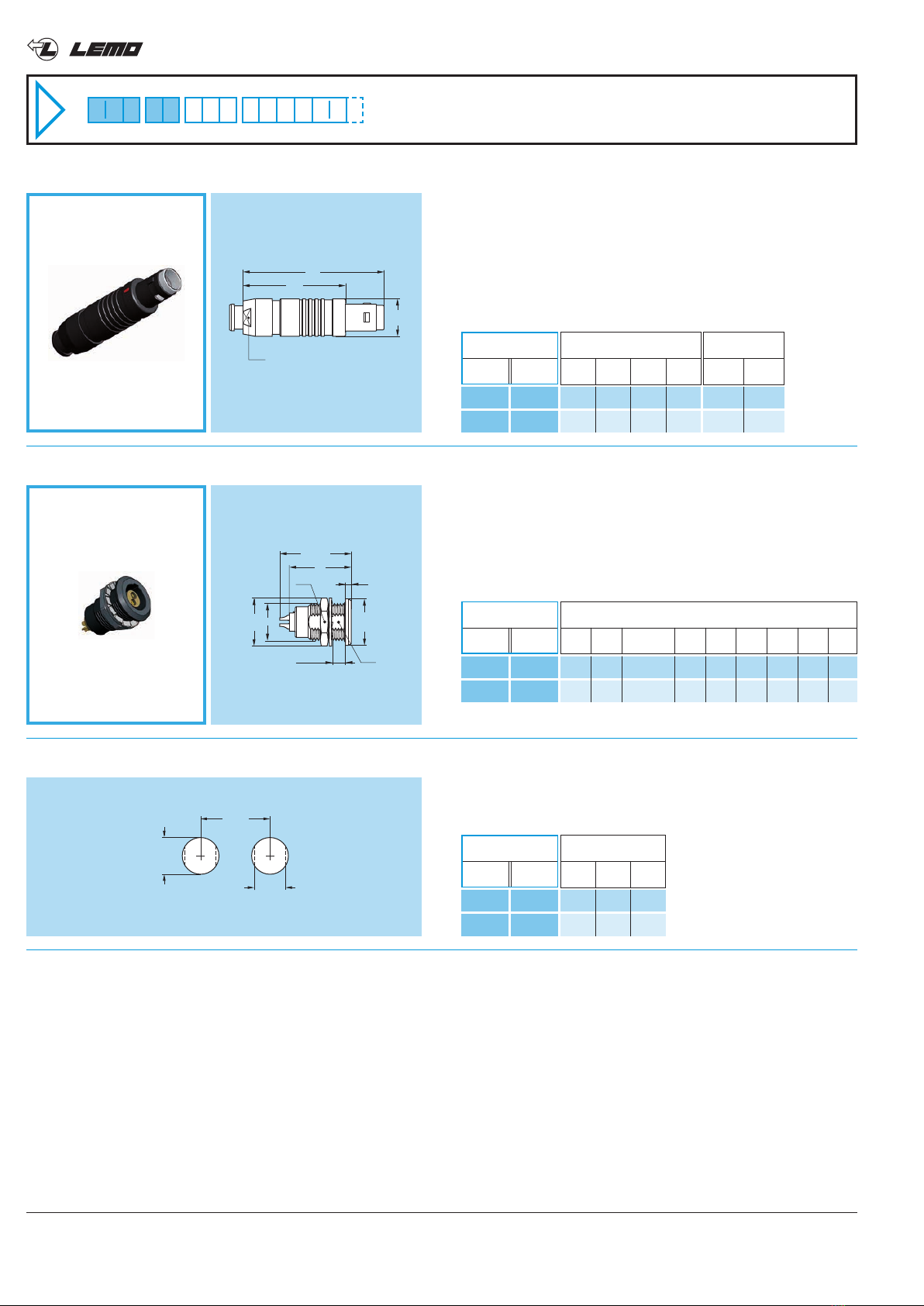
Precision modular connectors to suit your application
Since its creation in Switzerland in 1946 the LEMO Group has been recognized as a global leader of circular Push-Pull
connectors and connector solutions. Today LEMO and its affiliated companies, REDEL and COELVER, are active in
more than 80 countries with the help of over 40 subsidiaries and distributors.
Over 90000 connectors
The modular design of the LEMO range provides over 90000 connectors from miniature ø 3 mm to ø 50 mm, capable of
handling cable diameters up to 30 mm and for up to 114 contacts. This vast portfolio enables you to select the ideal con-
nector configuration to suit almost any specific requirement in most markets, including medical devices, test and meas-
urement instruments, machinery, audio video broadcast, telecommunications and military.
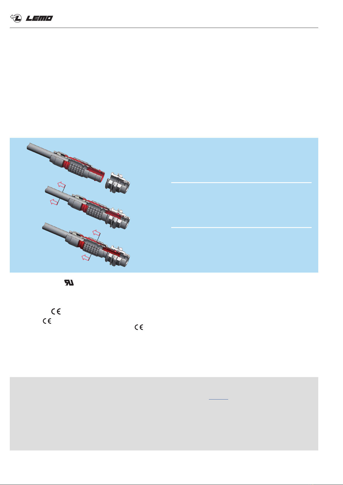
LEMO’s Push-Pull Self-Latching Connection System
This self-latching system is renowned worldwide for its easy and quick mating and unmating features. It provides absolute
security against vibration, shock or pull on the cable, and facilitates operation in a very limited space.
UL Recognition
LEMO connectors are recognized by the Underwriters Laboratories (UL). The approval of the complete system (LEMO
connector, cable and your equipment) will be easier because LEMO connectors are recognized.
CE marking
CE marking means that the appliance or equipment bearing it complies with the protection requirements of one or
several European safety directives. CE marking applies to complete products or equipment, but not to electrome-
chanical components, such as connectors.
RoHS
LEMO connector specifications conforms the requirements of the RoHS directive (2011/65/EU) of the European Parliament
and the latest amendments. This directive specifies the restrictions of the use of hazardous substances in electrical and
electronic equipment marketed in Europe.
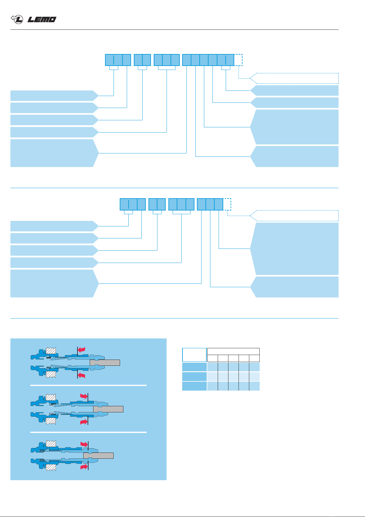
The LEMO self-latching system allows the connector
to be mated by simply pushing the plug axially into
the socket.
Once firmly latched, connection cannot be broken by
pulling on the cable or any other component part other
than the outer release sleeve.
When required, the connector is disengaged by a
single axial pull on the outer release sleeve.
This first disengages the latches and then withdraws
the plug from the socket.
Product safety notice & disclaimers
Please read and follow all instructions specified on the last page or on our website carefully and consult all relevent
national and international safety regulations for your application. Improper handling, cable assembly, or wrong use of
connectors can result in hazardous situations.
LEMO products and services are provided “as is.” LEMO makes no warranties or representations with regard to LEMO
product & services or use of them, express, implied or statutory, including for accuracy, completeness, or security.
In no event shall LEMO be liable for any direct, indirect, punitive, incidental, special consequential damages, to property
or life, whatsoever arising out of or connected with the use or misuse of LEMO’s products.

1www.lemo.com
®®
T series connectors have been specifically designed for outdoor applications. They include an inner sleeve and seals to
prevent penetration of solids or liquids.This series is watertight when mated to give a protection index of IP68 as per IEC
60529 standard and have the following main features:
- IP68 mated - Compatible with existing B sockets
- Push-Pull self-latching system - Same mounting hole as B sockets
- Mechanical key (FGG) with multiple keys - Black-chrome plated brass and plastic outershell available
to avoid cross-mating - Multipole types 2 to 32 contacts
- High packing density for space savings - For cables 1.0 up to 10.5 mm
- 360° shielding for full EMC shielding - Solder, crimp or print contacts
T series
1
37
2
462 5 4 1 6 9
5
63 7 8 10
Fixed socket
outer shell
earthing crown
hexagonal nut
insulator
female contact
o-ring
locking washer
4
3
6
5
1
2
7
Straight plug
outer shell
latch sleeve
inner shell
insulator
male contact
split insert carrier
earthing cone
gasket
collet
collet nut
4
3
6
5
1
2
7
8
9
10
FGG
FGG
PHG
PHG
EGG
EEG
HGG HEG
FFG
FGG EGG
L•G
HMG
FSG
FGG PHG
Straight plugsStraight plug
Elbow plug
Fixed sockets Free sockets
Chrome-plated housing models (page 3)
Straight plug Fixed socket
Plastic housing models (page 8)
Fixed sockets
Watertight or vacuumtight models (page 7)
Part Section Showing Internal Components

2 www.lemo.com
®®
Insert configuration (page 10)
Series
Model (page 6)
Alignment key (page 9)
Fixed socket
Insulator: PEEK
L = for solder or print contact
Y = for crimp contact
Insulator: PEEK
L = for solder contact
Y = for crimp contact
E G G 1 T 3 0 6 C L L
. . .
EGG.1T.306.CLL = fixed socket, nut fixing, with key (G), 1T series, multipole type with 6 contacts, outer shell in chrome-plated brass,
PEEK insulator, female solder contacts.
Z
F G G 1 T
Insert configuration (page 10)
Cable ø (page 13)
Collet type (page 13)
Housing:
C = Chrome plated brass
K = Black Chrome plated brass
B = POM (black)
Variant
3 0 6
Series
Model (page 3)
Alignment key (page 9)
C L A C 4 0
Contact:
A = male solder
L = female solder
C = male crimp
M = female crimp
Plug and free socket
Variant
. . .
FGG.1T.306.CLAC40Z = Straight plug with key (G) and cable collet for bend relief, 1T series, multipole type with 6 contacts, outer shell
in chrome-plated brass, PEEK insulator, male solder contacts, C type collet for 4.0 mm diameter cable and nut for fitting a bend relief.
Part Numbering System
Contact:
L = female solder
A = male solder
M = female crimp
C = male crimp
N = female print
D = male print
V = female elbow print
Housing:
C = Chrome plated brass
K = Black Chrome plated brass
B = POM
Mechanical latching characteristics
Fv: average latching force.
Fd: average unmating force with axial pull on
the outer shell.
Fa: average pull force with axial pull on the collet nut
Notes: forces were measured on outer shells not fitted with contacts.
Mechanical endurance: 3000 cycles. Average pull force (Fa) with axial
pull on the collet nut is about 50% of Fa values after 3000 cycles.
The values were measured according to the standard IEC 60512-7 test 13a.
1N = 0.102 kg.
Fv
Fd
Fa
Series
TT 0T 1T 2T 3T
Keyed watertight series
Force
(N)
Fv
Fd
Fa
14 15 16 20 28
12 13 14 15 24
80 130 250 250 400

®®
3
Chrome-plated housing models
7.0 33.2 25.2 5.5 5
9.5 39.0 29.0 7.5 7
12.0 46.0 35.0 11.0 9
15.0 55.0 43.0 14.0 12
18.8 64.0 49.0 16.0 14
Dimensions (mm)
A L M S1 S2
Reference
Model Series
2.4 3.0
1.0 4.5
1.3 6.5
1.3 8.5
2.6 10.5
Cable ø
min. max.
~M
~L
ø A
S 1
S 2
FGG Straight plug, cable collet
FGG TT
FGG 0T
FGG 1T
FGG 2T
FGG 3T
Note: 1) operating temperature is -20°C, +80°C for watertight or vacuumtight models fitted with an FPM (Viton®) o-ring and Epoxy.
2) IP68 achieved providing that the cable is perfectly circular and that assembly process ensures a high integrity seal.
3) average value.
4) depending of the size.
5) for chrome plated product (« C » material code).
Technical Characteristics
Electrical
Note: the various tests have been carried out with FGG and EGG connector
pairs, with chrome-plated brass shell and PEEK insulator.
Mechanical and Climatical
Characteristics Value Standard
> 3000 cycles IEC 60512-5 test 9a
up to 95% at 60° C
- 55° C, + 200° C / (-20°C, +80°C)
10-2000 Hz, 15g IEC 60512-4 test 6d
100 g, 6 ms IEC 60512-4 test 6c
> 1000h IEC 60512-6 test 11f
IP 68/IP 66 IEC 60529
From 85 N up to 300 N
50/175/21 IEC 60068-1
Endurance
Humidity
Temperature range 1)
Resistance to vibration
Shock resistance
Salt spray corrosion test 5)
Protection index (mated) 2)
Latching retention force 3) 4)
Climatical category
Value Standard
> 75 dB IEC 60169-1-3
> 40 dB IEC 60169-1-3
Characteristics
Shielding
efficiency
at 10 MHz
at 1 GHz
Note: 6) surface not conductive use socket with earthing tag (HMG).
Component Material Surface treatment
Brass Chrome
Brass Black chrome 6)
POM –
Brass/Bronze Nickel
Brass Nickel
Outershell and collet nut
Latch sleeve/earthing crown
Other metallic components
Material and treatments
Material Contact type
Male contact
Female contact
Brass (UNS C 34500)
Bronze (UNS C 54400)
Contacts
9.5 10.9 50.7 40.9 8.5 10 9
12.0 13.9 60.2 49.1 11.0 13 12
15.0 16.5 69.1 57.0 14.0 15 14
18.8 23.0 87.7 72.7 16.0 20 20
Dimensions (mm)
A B L M S1 S2 S3
Reference
Model Series
4.6 6.5
6.6 8.5
8.6 10.5
10.6 15.0
Cable ø
min. max.
~M
~L
ø A
ø B
S 1S 2S 3
FGG Straight plug, cable collet and oversize cable collet 1)
FGG 0T
FGG 1T
FGG 2T
FGG 3T
Note: 1) correspond to K type of collet, the fitting of oversize collets onto
this model allows them to be fitted to the cables that can be accommodated
by the next housing size up (see page 13).

4 www.lemo.com
®®
~M
~L
ø A
S 1
S 2
FFG Straight plug, non latching, cable collet
7.0 33.2 25.2 5.5 5
9.5 39.0 29.0 8.0 7
12.0 46.0 35.0 10.0 9
15.0 55.0 43.0 13.0 12
18.8 64.0 49.0 16.0 14
Dimensions (mm)
A L M S1 S2
Reference
Model Series
2.4 3.0
1.0 4.5
1.3 6.5
1.3 8.5
2.6 10.5
Cable ø
min. max.
FFG TT
FFG 0T
FFG 1T
FFG 2T
FFG 3T
L
M
~H
ø A
S 1
S 2
FSG Adjustable right angle plug
8 20.0 28.5 20.5 5 7.5
10 23.0 36.0 26.0 7 9.5
13 30.0 43.5 32.5 9 12.0
17 37.5 54.0 42.0 12 16.0
Dimensions (mm)
A H L M S1 S2
FSG TT
FSG 0T
FSG 1T
FSG 2T
Reference
Model Series
2.4 3.0
1.0 4.5
1.3 6.5
1.3 8.5
Cable ø
min. max.
~M
~L
ø A
S 1
S 2
7.0 32.7 24.7 5.5 6
9.5 38.0 28.0 7.5 7
12.0 45.0 34.0 11.0 9
15.0 54.0 42.0 14.0 12
18.8 62.0 47.0 16.0 15
Dimensions (mm)
A L M S1 S2
FGG TT
FGG 0T
FGG 1T
FGG 2T
FGG 3T
Reference
Model Series
2.4 3.0
1.0 4.5
1.3 6.5
1.3 8.5
2.6 10.5
Cable ø
min. max.
FGG Straight plug, cable collet and nut for fitting a bend relief 1)
Note: 1) to order, add a «Z» at the end of the reference.
The bend relief must be ordered separately (see page 19).

5www.lemo.com
®®
~L
ø A
S 1
S 2
7.0 32.0 5.5 5
9.5 38.0 8.0 7
12.0 43.5 10.0 9
15.0 52.0 14.0 12
18.8 61.5 16.0 14
Dimensions (mm)
A L S1 S2
PHG TT
PHG 0T
PHG 1T
PHG 2T
PHG 3T
Reference
Model Series
2.4 3.0
1.0 4.5
1.3 6.5
1.3 8.5
2.6 10.5
Cable ø
min. max.
PHG Free socket, cable collet
~L
ø A
S 1
S 2
PHG Free socket, cable collet and nut for fitting a bend relief 1)
7.0 31.5 5.5 6
9.5 37.0 8.0 7
12.0 42.5 10.0 9
15.0 51.0 14.0 12
18.8 60.0 16.0 15
Dimensions (mm)
A L S1 S2
PHG TT
PHG 0T
PHG 1T
PHG 2T
PHG 3T
Reference
Model Series
2.4 3.0
1.0 4.5
1.3 6.5
1.3 8.5
2.6 10.5
Cable ø
min. max.
9.5 10.9 49.7 8 10 9
12.0 13.9 58.2 10 13 12
15.0 16.5 66.6 13 15 14
18.8 23.0 85.5 16 20 20
Dimensions (mm)
A B L S1 S2 S3
Reference
Model Series
4.6 6.5
6.6 8.5
8.6 10.5
10.6 15.0
Cable ø
min. max.
~L
ø A
ø B
S 1S 2S 3
PHG Free socket, cable collet and oversize cable collet 1)
PHG 0T
PHG 1T
PHG 2T
PHG 3T
Note: 1) correspond to K type of collet, the fitting of oversize collets onto
this model allows them to be fitted to the cables that can be accommodated
by the next housing size up (see page 13).
Note: 1) to order, add a «Z» at the end of the reference.
The bend relief must be ordered separately (see page 19).

6 www.lemo.com
®®
E maxi
N
L maxi
M
ø A
e
ø B
S 1
S 2
EGG Fixed socket, nut fixing
EGG TT
EGG 0T
EGG 1T
EGG 2T
EGG 3T
Reference
Model Series
10.0 10.2 M7x0.5 5.5 16.0 1.2 13.5 6.3 9
12.0 12.5 M9x0.6 6.0 21.0 1.5 19.1 8.2 11
15.5 16.0 M12x1.0 6.0 23.0 1.8 21.5 10.5 14
18.5 19.6 M15x1.0 7.5 26.5 1.8 24.6 13.5 17
23.5 25.1 M18x1.0 9.6 30.1 2.5 25.0 16.5 22
Dimensions (mm)
A B e E L M N1) S1 S2
ø A
L maxi
E maxi
N
P
e
ø B
S 1
EEG Fixed socket, nut fixing (back panel mounting)
EEG TT
EEG 0T
EEG 1T
EEG 2T
EEG 3T
Reference
Model Series
Note: 1) maximum length with crimp contacts.
Ell TT
Ell 0T
Ell 1T
Ell 2T
Ell 3T
Reference
Model Series
6.4 7.1 12.5
8.3 9.1 14.5
10.6 12.1 18.5
13.6 15.1 22.5
16.6 18.1 27.0
Panel cut-out
B C L
1.0 0.4
2.5 0.4
4.5 0.7
6.0 0.8
9.0 1.0
Mounting nut torque (Nm)
Metal shell Plastic shell
ø C + 0.1
0
B + 0.1
0
L mini
Panel cut-out
10.0 10.0 M7x0.5 4.5 16.0 13.5 7 6.3
12.0 12.0 M9x0.6 6.5 21.0 19.1 9 8.2
15.5 16.0 M12x1.0 6.5 23.0 21.5 10 10.5
18.5 20.0 M15x1.0 7.5 26.5 24.6 11 13.5
23.5 24.0 M18x1.0 7.5 30.1 25.0 12 16.5
Dimensions (mm)
A B e E L N1) PS1
13.1 11.6 24
15.1 13.6 26
20.1 18.6 29
Dim. (mm)
A B L
Series
0T
1T
2T
19 18.2 M13x0.75 4.0 18.5 5 16.0 11.5 16
21 19.2 M15x1.00 5.8 21.0 5 18.5 13.5 17
25 27.0 M20x1.00 6.5 24.1 5 21.5 18.5 24
Dimensions (mm)
A B e E L M N S1 S2
LlG 0T
LlG 1T
LlG 2T
Reference
Model Series
Note: Only available with solder or crimp contacts.
LEG model is with LED flange, LNG model is with narrow LED flange and
LMG model is with single standby LED flange.
L mini
B+ 0.1
0
ø A+ 0.1
0
e
ø B
S 1
E maxi
S 2 NM
L
AWG 28 /AWG 30
ø A
Blue (GND)Green (GND)
Red (GND)
V+
(3.3-3.6 Vdc)
LlG Fixed socket, nut fixing, key (G) or keys (A…L)

7www.lemo.com
®®
Watertight or vacuumtight models
ø A
L maxi
N
E maxi
P
e
ø B
S 1
ø A
L maxi
N
E maxi
P
e
ø B
S 1
L maxi
N
ø A
E maxi
e
M
ø B
S 1
S 2
HGG Fixed socket, nut fixing, watertight or vacuumtight
HEG Fixed socket, nut fixing, watertight or vacuumtight (back panel mounting)
HMG Fixed socket with earthing tag, nut fixing, watertight or vacuumtight (back panel mounting)
HMG TT
HMG 0T
HMG 1T
HMG 2T
Reference
Model Series
HEG TT
HEG 0T
HEG 1T
HEG 2T
Reference
Model Series
Reference
Model Series
HGG.0T.305.CLLP (5 contacts, resin potted)
HGG.0T.305.CLLPV (5 contacts, resin potted and vacuumtight tested)
These models are identified by a letter «P» at the end of the reference. Most of these models are also available in a vacuum-
tight version. Such models are identified by an additional letter «V» at the end of the part number (certificate on request).
Epoxy resin is used to seal these models. The temperature range is -20°C / +80°C.
Part Number Example
ø C + 0.1
0
B + 0.1
0
L mini
Panel cut-out
10.0 10.2 M7x0.5 5.5 18.0 1.2 15.0 6.3 9
12.0 12.5 M9x0.6 6.5 22.0 1.5 18.5 8.2 11
15.5 16.0 M12x1.0 6.0 26.0 1.8 21.5 10.5 14
18.5 19.6 M15x1.0 8.0 30.5 1.8 25.0 13.5 17
Dimensions (mm)
A B e E L M N1) S1 S2
10.0 10.0 M7x0.5 4.5 18.0 15.0 7 6.3
12.0 12.0 M9x0.6 6.5 22.0 18.5 9 8.2
15.5 16.0 M12x1.0 6.5 26.0 21.5 10 10.5
18.5 20.0 M15x1.0 7.5 30.5 25.0 11 13.5
Dimensions (mm)
A B e E L N PS1
10.0 10.0 M7x0.5 4.5 18.0 15.0 7 6.3
12.0 12.0 M9x0.6 6.5 22.0 18.5 9 8.2
15.5 16.0 M12x1.0 6.5 26.0 21.5 10 10.5
18.5 20.0 M15x1.0 7.5 30.5 25.0 11 13.5
Dimensions (mm)
A B e E L N PS1
Hll TT
Hll 0T
Hll 1T
Hll 2T
Reference
Model Series
6.4 7.1 12.5
8.3 9.1 14.5
10.6 12.1 18.5
13.6 15.1 22.5
Panel cut-out
B C L
1.0 0.4
2.5 0.4
4.5 0.7
6.0 0.8
Mounting nut torque (Nm)
Metal shell Plastic shell
HGG TT
HGG 0T
HGG 1T
HGG 2T

8 www.lemo.com
®®
Plastic housing models
~L
ø A
~M
S 2
FGG 0T
FGG 1T
Reference
Model Series
1.0 4.5
1.3 6.5
Cable ø
min. max.
FGG Straight plug, cable collet and nut for fitting a bend relief, POM outer shell
EGG Fixed socket, nut fixing, POM outer shell
E maxi
N
L maxi
M
ø A
e
ø B
S 1
S 2
EGG 0T
EGG 1T
Reference
Model Series
Note: 1) maximum length with crimp contacts.
Ell 0T
Ell 1T
Reference
Model Series
8.3 9.1 14.5
10.6 12.1 18.5
Panel cut-out
B C L
ø C + 0.1
0
B + 0.1
0
L mini
Panel cut-out
12.0 12.5 M9x0.6 6.0 21.0 1.5 19.1 8.2 11
15.5 16.0 M12x1.0 6.0 23.0 1.8 21.5 10.5 14
Dimensions (mm)
A B e E L M N1) S1 S2
9.7 38.5 28.5 8
13.0 45.0 34.0 10
Dimensions (mm)
A L M S2

9www.lemo.com
®®
Alignment Key
Key
G
AL
D
J 1)
J
Contact type
Plug Socket
male female
male female
male female
female male
female male
G
A
D
L
J
Note: 1) for 2T and 3T series.

10 www.lemo.com
®®
Insert configurations
TT 0.5 l l l l30 32 28
0T 0.9 l l l l20 32 20
1T 1.3 l l l l20 26 18
2T 2.0 l l l l16 18 12
3T 3.0 l l ll–12 14 10
302
303
304
305
306
1.00 0.95 3.5
1.00 1.05 10.0
1.50 1.35 15.0
2.10 1.75 25.0
2.10 1.55 35.0
TT 0.5 l l l l30 32 28
0T 0.9 l l l l20 32 20
1T 1.3 l l l l20 26 18
2T 1.6 l l l l18 22 14
3T 2.0 l l l ll16 18 12
0.80 0.95 3.0
1.20 0.90 8.0
1.30 1.55 12.0
2.40 1.85 17.0
1.90 1.50 25.0
TT 0.5 l l l l30 32 28
0T 0.7 l l l l22 32 22
1T 0.9 l l l l22 32 20
2T 1.3 l l l l20 26 18
3T 2.0 l l l l16 18 12
0.80 0.65 2.0
0.85 0.70 7.0
1.35 1.45 10.0
1.85 1.85 15.0
1.45 1.25 19.0
TT 0.35 l – l –30 – – 0.70 1.00 1.7
0T 0.5 l ll1) l l28 32 28
1T 0.7 l l l l22 32 22
0.85 0.65 2.5
1.05 1.20 7.0
2
3
4
6
5
Multipole
Reference
Series
Contact ø (mm)
Solder
Crimp
Print (straight)
Print (elbow)
Solder (max.)
min.
max.
Contact
type
Solder
contact
AWG
Crimp
Test voltage (kV rms)
Contact-contact
Test voltage (kV rms)
Contact-shell
Rated current (A)
Note: 1) available only for connectors fitted with male contacts. lFirst choice alternative lSpecial order alternative
305
0T 0.7 l l l l22 32 22
1T 0.9 l l l l22 32 20
2T 1.3 l l l l20 26 18
3T 1.6 l l l l18 22 14
1.00 0.70 6.5
1.25 1.15 9.0
1.75 1.60 14.0
1.90 1.25 19.0
5
Solder contacts
Crimp contacts
14
2
3
1 4
23

11www.lemo.com
®®
306
6TT 0.35 l – ––30 – –
2T 1.3 l l l l20 26 18
3T 1.6 l l l l18 22 14
0.60 0.75 1.5
1.35 1.45 12.0
1.60 1.15 17.0
307
308
308
309
310
7
8
8
9
10
0T 0.5 l ll1) l l28 32 28
1T 0.7 l l l l22 32 22
2T 1.3 l l l l20 26 18
3T 1.6 l l l ll18 22 14
0.80 0.70 2.5
0.95 1.05 7.0
1.75 1.60 11.0
1.70 1.25 15.0
1T 0.5 l l1) l l28 32 28
2T 0.9 l l l l22 32 20
3T 1.3 l l l l20 26 18
0.90 1.50 2.5
1.45 1.30 8.0
1.25 0.90 12.0
1T 0.7 l l l l22 32 22 0.95 1.15 5.0
2T 0.9 l l l l22 32 20
3T 1.3 l l l l20 26 18
1.50 1.25 10.0
1.65 1.15 13.0
0T 0.5 l ll1) l l28 32 28
3T l l l –
0.60 0.50 2.0
1.35 1.05
8x1.3 20 26 18
1x2.0 16 18 12
6.0
15.0
312
12
312
12
0T 0.35 l – l –30 – – 0.80 1.00 1.5
2T 0.7 l l l l22 32 22
3T 0.9 l l l l22 32 20
1.25 1.35 7.0
1.45 1.00 9.0
Note: 1) available only for connectors fitted with male contacts.
Multipole
Reference
Series
Contact ø (mm)
Solder
Crimp
Print (straight)
Print (elbow)
Solder (max.)
min.
max.
Contact
type
Solder
contact
AWG
Crimp
Test voltage (kV rms)
Contact-contact
Test voltage (kV rms)
Contact-shell
Rated current (A)
lFirst choice alternative lSpecial order alternative
314
14 1T 0.5 l l1) l l28 32 28
2T 0.7 l l l l22 32 22
3T 0.9 l l l l22 32 20
0.80 1.20 2.0
1.15 1.35 6.5
1.20 1.20 9.0
Solder contacts
Crimp contacts
14
2
3
1 4
23

12 www.lemo.com
®®
316
16
316
16
318
18
1T 0.5 l l1) l ll28 32 28 0.80 1.25 1.5
2T 0.7 l l l l22 32 22
3T 0.9 l l l l22 32 20
0.95 1.25 6.0
1.20 0.85 8.0
2T 0.7 l l l l22 32 22
3T 0.9 l l l l22 32 20
0.85 1.20 5.5
1.20 1.05 7.0
320
20
319
19
2T 0.7 l l l l22 32 22 0.95 1.25 5.0
3T 0.7 l l l l22 32 22 1.00 0.90 6.0
322
22
3T 0.7 l l l ll22 32 22 1.00 0.90 5.5
324
24
3T 0.7 l l l l22 32 22 0.80 0.70 3.5
3T 0.7 l l l l22 32 22 0.95 0.80 4.0
330
30
332
32
2T 0.5 l – l l28 – – 0.80 1.20 1.5
326
26 2T 0.5 l – l l28 – –
3T 0.7 l l l l22 32 22
0.95 1.30 2.0
0.95 0.70 4.0
Multipole
Reference
Series
Contact ø (mm)
Solder
Crimp
Print (straight)
Print (elbow)
Solder (max.)
min.
max.
Contact
type
Solder
contact
AWG
Crimp
Test voltage (kV rms)
Contact-contact
Test voltage (kV rms)
Contact-shell
Rated current (A)
Solder contacts
Crimp contacts
14
2
3
1 4
23
Note: 1) available only for connectors fitted with male contacts. lFirst choice alternative lSpecial order alternative

13www.lemo.com
®®
Collets
Cable ø (mm)
min. max.
Type Note
2.6 3.0
3.1 3.5
3.6 4.0
4.1 4.5
4.6 5.0
5.1 5.5
5.6 6.0
6.1 6.5
6.6 7.0
7.1 7.5
7.6 8.0
8.1 8.5
8.6 9.0
9.1 9.5
9.6 10.0
10.1 10.5
10.6 12.0
12.1 12.8
12.9 13.5
13.6 14.0
14.1 15.0
C30
C35
C40
C45
C50
C55
C60
C65
C70
C75
C80
C85
C90
C95
C10
C11
K11
K12
K13
K14
K15 5)
3T
Note
4)
4)
4)
4)
Cable ø (mm)
min. max.
Type
1.3 1.5
1.6 2.0
2.1 2.5
2.6 3.0
3.1 3.5
3.6 4.0
4.1 4.5
4.6 5.0
5.1 5.5
5.6 6.0
6.1 6.5
6.6 7.0
7.1 7.5
7.6 8.0
8.1 8.5
8.6 9.0
9.1 9.5
9.6 10.0
10.1 10.5
C15
C20
C25
C30
C35
C40
C45
C50
C55
C60
C65
C70
C75
C80
C85
K90
K95
K10
K11
2T
Note: all dimensions are in millimetres.
1) the inner diameter of the smallest bend relief available is 2.5 mm (in TPU) / 1.7 mm (in silicone).
2) for 1B bend relief.
3) for 2B bend relief.
4) for 3B bend relief.
5) the inner diameter of the largest bend relief available is 14.5 mm.
1.3 1.5
1.6 2.0
2.1 2.5
2.6 3.0
3.1 3.5
3.6 4.0
4.1 4.5
4.6 5.0
5.1 5.5
5.6 6.0
6.1 6.5
6.6 7.0
7.1 7.5
7.6 8.0
8.1 8.5
C15
C20
C25
C30
C35
C40
C45
C50
C55
C60
C65
K70
K75
K80
K85
1T
1.0 1.2
1.3 1.5
1.6 2.0
2.1 2.5
2.6 3.0
3.1 3.5
3.6 4.0
4.1 4.5
4.6 5.0
5.1 5.5
5.6 6.0
6.1 6.5
C10
C15
C20
C25
C30
C35
C40
C45
K50
K55
K60
K65
Cable ø (mm)
min. max.
Type
0T
TT 2.4 2.6
2.7 3.0
C27
C31
Note
1)
1)
1)
2)
2)
2)
2)
3)
3)
3)
3)
C type K type
oversize
cable collet

14 www.lemo.com
®®
ø (mm) Cond. AWG
A C min. max.
Types
TT 302 /303 /304 0.5 0.45 1 32 28
0T 302 /303
304 /305
306 /307 /309
1.10 1 24 20
0.9 0.80 2 26 22
0.45 2 32 28
0.80 1 26 22
0.7
0.45 2 32 28
0.5 0.45 1 32 28
1T 302 /303
304 /305
306 /307 /308
310 /314 /316
1.40 1 20 18
1.3
1.10 2 24 20
1.10 1 24 20
0.9
0.80 2 26 22
0.80 1 26 22
0.7
0.45 2 32 28
0.5 0.45 1 32 28
2T 2.40 1 16 12
2.0
1.90 2 18 14
1.90 1 18 14
1.6
1.40 2 22 18
1.40 1 20 18
1.3 1.10 2 24 20
0.80 2 26 22
1.10 1 24 20
0.9 0.80 2 26 22
0.45 2 32 28
0.80 1 26 22
0.7
0.45 2 32 28
3T
FGG.00.554.ZZC EGG.00.654.ZZM
FGG.0B.560.ZZC EGG.0B.660.ZZM
FGG.0B.561.ZZC EGG.0B.661.ZZM
FGG.0B.562.ZZC EGG.0B.662.ZZM
FGG.0B.555.ZZC EGG.0B.655.ZZM
FGG.0B.556.ZZC EGG.0B.656.ZZM
FGG.0B.554.ZZC –
FGG.1B.565.ZZC EGG.1B.665.ZZM
FGG.1B.566.ZZC EGG.1B.666.ZZM
FGG.1B.560.ZZC EGG.1B.660.ZZM
FGG.1B.561.ZZC EGG.1B.661.ZZM
FGG.1B.555.ZZC EGG.1B.655.ZZM
FGG.1B.556.ZZC EGG.1B.656.ZZM
FGG.1B.554.ZZC –
FGG.2B.575.ZZC EGG.2B.675.ZZM
FGG.2B.576.ZZC EGG.2B.676.ZZM
FGG.2B.570.ZZC EGG.2B.670.ZZM
FGG.2B.571.ZZC EGG.2B.671.ZZM
FGG.2B.565.ZZC EGG.2B.665.ZZM
FGG.2B.566.ZZC EGG.2B.666.ZZM
FGG.2B.567.ZZC EGG.2B.667.ZZM
FGG.2B.560.ZZC EGG.2B.660.ZZM
FGG.2B.561.ZZC EGG.2B.661.ZZM
FGG.2B.562.ZZC EGG.2B.662.ZZM
FGG.2B.555.ZZC EGG.2B.655.ZZM
FGG.2B.556.ZZC EGG.2B.656.ZZM
Contact part number
Male Female
302
303
304 /305
306 /307
308 /310
312 /314 /316
318 /319
Insulator part number
Male contact Female contact
FGG.00.30l.YL EGG.00.40l.YL
FGG.0B.30l.YL EGG.0B.40l.YL
FGG.0B.30l.YL –
FGG.1B.30l.YL EGG.1B.40l.YL
FGG.1B.3ll.YL –
FGG.2B.302.YL EGG.2B.402.YL
FGG.2B.303.YL EGG.2B.403.YL
FGG.2B.30l.YL EGG.2B.40l.YL
FGG.2B.3ll.YL EGG.2B.4ll.YL
Note: 1) for 309 type the insulator part number is FGG.3B.309.ML (male contact) and EGG.3B.409.ML (female contact).
Spare parts for crimp contacts
Fig.
FGG.3B.580.ZZC EGG.3B.680.ZZM
FGG.3B.575.ZZC EGG.3B.675.ZZM
FGG.3B.576.ZZC EGG.3B.676.ZZM
FGG.3B.570.ZZC EGG.3B.670.ZZM
FGG.3B.571.ZZC EGG.3B.671.ZZM
FGG.3B.565.ZZC EGG.3B.665.ZZM
FGG.3B.566.ZZC EGG.3B.666.ZZM
FGG.3B.567.ZZC EGG.3B.667.ZZM
FGG.3B.560.ZZC EGG.3B.660.ZZM
FGG.3B.561.ZZC EGG.3B.661.ZZM
FGG.3B.562.ZZC EGG.3B.662.ZZM
FGG.3B.555.ZZC EGG.3B.655.ZZM
FGG.3B.556.ZZC EGG.3B.656.ZZM
302
303 /304 /309
305 /306 /307
308 /309 /310
312 /314
316 /318
320 /322 /324
326 /330
3.0 3.20 1 14 10
2.40 1 16 12
2.0
1.90 2 18 14
1.90 1 18 14
1.6
1.40 2 22 18
1.40 1 20 18
1.3 1.10 2 24 20
0.80 2 26 22
1.10 1 24 20
0.9 0.80 2 26 22
0.45 2 32 28
0.80 1 26 22
0.7
0.45 2 32 28
FGG.3B.302.YL EGG.3B.402.YL
FGG.3B.30l.YL 1) EGG.3B.40l.YL 1)
FGG.3B.30l.YL EGG.3B.40l.YL
FGG.3B.3ll.YL 1) EGG.3B.4ll.YL 1)
FGG.3B.3ll.YL EGG.3B.4ll.YL

15www.lemo.com
®®
These positioners are suitable for use with both manual
and pneumatic crimping tools according to the MIL-C-
22520/7-01 standard.
male female
ø A ø C
ø A ø C
Fig. 1
ø A ø C
ø A ø C
Fig. 2
FGG
EGG
FGG
EGG
Note: a wide variation of strand number and diameter
combinations are quoted as being AWG, some of which
do not have a large enough cross section to guarantee
a crimp as per either MIL-C-22520/1-01 or /7-01.
DCE Positioners ø 0.5, 0.7, 0.9, 1.3 mm
DCE.91.050.0VC DCE.91.050.0VM
DCE.91.090.BVC DCE.91.090.BVM
DCE.91.090.AVC DCE.91.090.AVM
DCE.91.070.BVC DCE.91.070.BVM
DCE.91.050.BVC DCE.91.050.BVM
DCE.91.131.BVC DCE.91.131.BVM
DCE.91.091.BVC DCE.91.091.BVM
DCE.91.071.BVC DCE.91.071.BVM
DCE.91.051.BVC DCE.91.051.BVM
DCE.91.202.BVCM
DCE.91.162.BVCM
DCE.91.132.BVC DCE.91.132.BVM
DCE.91.132.CVC DCE.91.132.CVM
DCE.91.092.BVC DCE.91.092.BVM
DCE.91.092.AVC DCE.91.092.AVM
DCE.91.072.BVC DCE.91.072.BVM
Positioners part number
Male contact Female contact
Note: these turrets can be used with manual crimping
tool according to MIL-C-22520/1-01 standard.
DCE Turret for ø 1.6, 2.0, 3.0, 4.0 mm
male female
Note: each insulator can be used both for crimp con-
tacts of normal shape (fig. 1) or with reduced solder
cups (fig. 2).
FGG-EGG Insulators
FGG-EGG Crimp contacts
Tools for crimp contacts
Extractors part
number for male/
female contacts
DCC.05.02B.LAG
DCC.09.05B.LAG
DCC.07.04B.LAG
DCC.05.02B.LAG
DCC.13.15B.LAG
DCC.09.05B.LAG
DCC.07.04B.LAG
DCC.05.02B.LAG
DCC.20.25B.LAG
DCC.16.25B.LAG
DCC.13.15B.LAG
DCC.09.05B.LAG
DCC.07.04B.LAG
Types
TT 302 /303 /304
0T 302 /303
304 /305
306 /307 /309
1T 302 /303
304 /305
306 /307 /308
310 /314 /316
2T
3T
302
303
304 /305
306 /307
308 /310
312 /314 /316
318 /319
FGG EGG
DCE.91.303.BVCM
DCE.91.203.BVCM
DCE.91.163.BVCM
DCE.91.133.BVC DCE.91.133.BVM
DCE.91.093.BVC DCE.91.093.BVM
DCE.91.093.BVG DCE.91.093.BVU
DCE.91.073.BVC DCE.91.073.BVM
DCC.30.35B.LAG
DCC.20.25B.LAG
DCC.16.25B.LAG
DCC.13.15B.LAG
DCC.09.05B.LAG
DCC.07.04B.LAG
302
303 /304 /309
305 /306 /307
308 /309 /310
312 /314
316 /318
320 /322 /324
326 /330
DCC Manual extractors

16 www.lemo.com
®®
Spare parts
eL
ø B
A
Note: 3T series fixed and free sockets for back panel mounting are always
delivered with a conical nut.
To order this accessory separately, use the above part numbers.
See page 20 for the tooling.
lMaterial: Chrome-plated brass (Ni 3 µm + Cr 0.3 µm)
GEC Conical nuts
TT
0T
1T
2T
3T
Series
GEC.00.240.LC
GEC.0S.240.LC
GEC.1S.240.LC
GEC.2S.240.LC
GEC.3S.240.LC
Part number
8 10 M7 x 0.5 2.5
10 12 M9 x 0.6 2.5
13 16 M12 x 1.0 3.2
17 20 M15 x 1.0 3.8
20 24 M18 x 1.0 4.5
Dimensions (mm)
A B e L
ø C L
ø A
Note: to order this accessory separately, use the above part numbers.
eL
A
ø B
Note: to order this part separately, use the above part numbers. The last
letters «LN» of the part number refer to the nut material and treatment. If a
nut in aluminium alloy or stainless steel is desired, replace the last letters
of the part number by «PT» or «AZ» respectively.
See page 20 for the tooling.
lMaterial: Nickel-plated bronze (3 µm)
GBA Locking washers
TT
0T
1T
2T
3T
Series
GBA.00.250.FN
GBA.0S.250.FN
GBA.1S.250.FN
GBA.2S.250.FN
GBA.3S.250.FN
Part number
9.5 7.1 1.0
12.5 9.1 1.0
16.0 12.1 1.0
19.5 15.1 1.2
25.0 18.1 1.4
Dimensions (mm)
A C L
lMaterial: Nickel-plated brass (3 µm), Natural anodized aluminium alloy, Stainless steel
GEA Hexagonal nuts
TT
0T
1T
2T
3T
Series
GEA.00.240.LN
GEA.0S.240.LN
GEA.1S.240.LN
GEA.2S.240.LN
GEA.3S.240.LN
Part number
9 10.2 M7 x 0.5 2.0
11 12.4 M9 x 0.6 2.0
14 15.8 M12 x 1.0 2.5
17 19.2 M15 x 1.0 2.7
22 25.0 M18 x 1.0 3.0
Dimensions (mm)
A B e L

17www.lemo.com
®®
e
ø A
ø B
L
ø B
L
e
ø A
Model 2
Model 1
Note: TT, 0T, 1T and 2T series fixed and free sockets for back panel
mounting are always delivered with this notched nut.
To order this accessory separately, use the above part numbers.
See page 21 for the tooling.
lMaterial: Chrome-plated brass (Ni 3 µm + Cr 0.3 µm)
GEG Notched nuts
TT
0T
1T
2T
Series
1
1
1
2
Model
GEG.00.240.LC
GEG.0S.240.LC
GEG.1S.240.LC
GEG.2S.240.LC
Part number
8.6 10 M7 x 0.5 2.5
10.5 12 M9 x 0.6 2.5
14.0 16 M12 x 1.0 3.5
17.5 20 M15 x 1.0 3.5
Dimensions (mm)
A B e L

18 www.lemo.com
®®
Accessories
N
ø A
L
B
sliding loop
BFG Blanking caps for plugs
7.0 4.3 9.0 60
9.5 5.0 11.0 85
12.0 6.3 12.4 85
15.0 6.4 13.8 85
18.8 6.4 17.6 120
Dimensions (mm)
A B L N1)
N
ø 3.5
ø A
L
B
BHG Blanking caps for fixed plugs
lBody material: Chrome-plated brass (Ni 3 µm)
lLanyard material: Stainless steel
lCrimp ferrule material: Nickel-plated brass + polyolefin
lO-ring material: Silicone
lOperating temperature: -50°/135°C (Silicone rubber & Polyolefine)
l Watertightness: IP68 according to IEC 60529
BFG.TT.100.CAS
BFG.0T.100.CAS
BFG.1T.100.CAS
BFG.2T.100.CAS
BFG.3T.100.CAS
Part number
BHG.TT.100.CAS
BHG.0T.100.CAS
BHG.1T.100.CAS
BHG.2T.100.CAS
BHG.3T.100.CAS
Part number
N
ø 3.5
ø A
L
M
B
BRE Blanking caps for sockets
N
ø A
L
M
B
sliding loop
BRF Blanking caps for free sockets
7.0 4.3 10.4 2.4 60
9.5 5.0 13.2 3.2 85
12.0 6.3 15.1 4.2 85
15.0 6.4 17.1 5.2 85
18.8 6.4 21.2 6.4 120
Dimensions (mm)
A B L M N1)
lBody material: Chrome-plated brass (Ni 3 µm)
lLanyard material: Stainless steel
lCrimp ferrule material: Nickel-plated brass + polyolefin
lOperating temperature: -50°/135°C (Silicone rubber & Polyolefine)
l Watertightness: IP68 according to IEC 60529
BRF.TT.200.CAZ
BRF.0T.200.CAZ
BRF.1T.200.CAZ
BRF.2T.200.CAZ
BRF.3T.200.CAZ
Part number
BRE.TT.200.CAZ
BRE.0T.200.CAZ
BRE.1T.200.CAZ
BRE.2T.200.CAZ
BRE.3T.200.CAZ
Part number
Note: 1) the tolerance on this dimension is ± 5 mm.
Table of contents
Other Lemo Cables And Connectors manuals
Popular Cables And Connectors manuals by other brands

Fluke
Fluke PK-PPC-BG-CVU PN 3070389 DVU installation guide

Roland
Roland digital snake S-4000-SP owner's manual

Energenie
Energenie DSP-HDMI-81 user manual

Project Source
Project Source EC0720WH quick start guide

Wiremold
Wiremold PLUGMOLD PLUS NM2000 installation instructions

3M
3M MS2 Sealant Box 4075-S instructions