LENCO Auto Glide User manual

3-11-11
Auto Glide
Boat Control System
TM
Auto Glide
Boat Control System
TM
Owner’s Manual B
Owner’s Manual B
Please visit our website to view up-to-date information and various
videos which may be beneficial to you. www.lencoautoglide.com
Operational Instructions

2
AUTO GLIDE OPERATION INSTRUCTIONS
Once the Home Roll Default Position and Home Pitch Default Position have been saved, the Auto Glide can provide
you with full automatic boat control. This section describes how to operate the Auto Glide in both AUTOMATIC and
MANUAL MODES.
Here is the list of topics we will cover in this section:
I. KEY PAD OVERVIEW………………………………………………………………………………………………………………….
3 - 5
A. KEY PAD BUTTONS………………………………………………………………………………………………………………….
3
B. KEY PAD BUTTON LED INDICATORS………………………………………………………………………………….
3
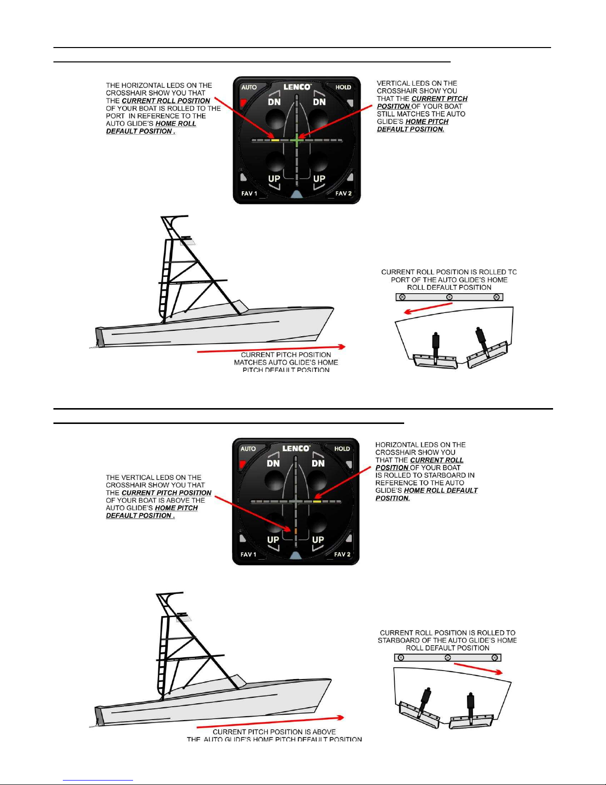
C. CROSSHAIR LED INDICATORS……………………………………………………………………………………………..
4 - 5
II. AUTOMATIC OPERATIONAL MODES…………………………………………………………………………………..
6 - 22
A. IDLE MODE…………………………………………………………………………………………………………………………………
6 - 8
1. ENTERING IDLE MODE …………………………………………………………………………………………………………
6 - 7
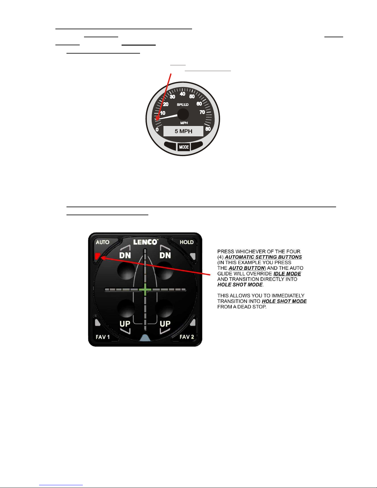
2. EXITING IDLE MODE INTO HOLE SHOT MODE……………………………………………………………………
8
B. HOLE SHOT MODE……………………………………………………………………………………………………………………
9 - 14
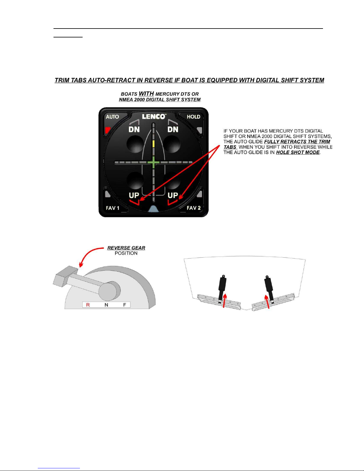
1. TRIM TABS AUTO-RETRACT IN REVERSE BOAT EQUIPPED WITH DIGITAL SHIFT….…...
10
2. SMOOTH WATER CONDITIONS: TRANSITION - HOLE SHOT TO PLANING MODE…………..
11
3. ROUGH WATER HOLE SHOT……………………………………………………………………………………………….
12
4. ROUGH WATER CONDITIONS: TRANSITION - HOLE SHOT TO PLANING MODE…………….
13
5. OVERRIDING ROUGH WATER HOLE SHOT MODE…………………………………………………………….
14
C. PLANING MODE……………………………………………………………………………………………………………………..…
15 - 22
1. ROLL CORRECTION……………………………………………………………………………………………………………..
16 - 17
2. PITCH CORRECTION…………………………………………………………………………………………………………….
18 - 19
3. YAW LOCK OUT…………………………………………………………………………………………………..……………….
20
4. RAPID DECELERATION……………………………………………………………………………………………….……….
21
5. EXITING PLANING MODE…………………………………………………………………………………………….……….
22
III. AUTOMATIC SETTINGS………………………………………………………………………………………..……………………….
23 - 26
A. AUTO SETTING………………………………………………………………………………………………………………..……….
23 - 24
B. FAV 1, FAV 2, and HOLD SETTINGS…………………………………………………………………………………….
24 - 26
1. SAVING “FAV 1” and “FAV 2” HOME ROLL AND PITCH POSITIONS………………………………..
24 - 25
2. RESETTING “FAV 1” AND “FAV 2” HOME ROLL AND PITCH POSITIONS………………………..
25
3. SAVING “HOLD” HOME ROLL AND PITCH POSITIONS………………………………………………………
26
IV. MANUAL OPERATION MODES……………………………………………………………………………………………….
27 - 32
A. MANUAL MODE………………………………………………………………………………………………………………………..
27 - 29
1. EXITING MANUAL MODE………………………………………………………………………………………………………
29
B. LIMP HOME MODE…………………………………………………………………………………………………………………..
29 - 32
V. SYSTEM FAILURE WARNING MESSAGES…………………………………………………………………………
33 - 38
A. DATA LOSS FAILURE …………………………………………………………………………………………………………….
33
B. GPS DATA LOSS …………………………………………………………………………………………………………………….
33
C. ENGINE DATA LOSS………………………………………………………………………………………………………………
34
D. KEY PAD COMMUNICATION LOSS ……………………………………………………………………………………
35
E. REACQUIRED DATA LOSS ………………………………………………………………………………………………….
36
F. ACTUATOR OVER-AMPERAGE…………………………………………………………………………………………..
37 - 38
G. CONTROL BOX OUT OF OPERATIONAL TOLERANCE …………………………………………………
38

3
I. KEY PAD OVERVIEW
A. KEY PAD BUTTONS
The Auto Glide Key Pad has two (2) Bow Down and two (2) Bow Up buttons that provide manual control of the
trim tabs at any time. There are also four (4) Automatic Setting Buttons on the outer corners of the key pad that
enable you to select up to four different automatic Home Roll and Pitch positions that the Auto Glide will use to
level the boat.
DN DN
AUT
O
UP UP
F
H
FA
O
AV
L
V1
D
2
“AUTO” AUTOMATIC
SETTING BUTTON
“FAV 1”
BUTTON
AUTOMATIC
SETTING “FAV 2”
BUTTON
AUTOMATIC
SETTING
PORT
BOW DOWN
BUTTON
PORT
BOW UP
BUTTON
STARBOARD
BOW DOWN
BUTTON
STARBOARD
BOW UP
BUTTON
“HOLD”
BUTTON
AUTOMATIC
SETTING
KEY PAD - BUTTON OVERVIEW
B. KEY PAD BUTTON LED INDICATORS
Each of the Key Pad Buttons also has a corresponding LED Indicator that illuminates to indicate that the button is
being activated (either manually or automatically).
DN DN
AUTO
UP UP
F
H
F
A
O
A
V
L
V
1
D
2
HORIZONTAL
CROSSHAIR
LED INDICATORS
VERTICAL
CROSSHAIR
LED INDICATORS
BOW DOWN BUTTON
LED INDICATORS
BOW UP BUTTON
LED INDICATORS
“AUTO” AUTOMATIC
SETTING LED
INDICATOR
“FAV 1”AUTOMATIC
SETTING LED
INDICATOR
“FAV 2”AUTOMATIC
SETTING LED
INDICATOR
“HOLD”AUTOMATIC
SETTING LED
INDICATOR
KEY PAD - LED INDICATOR OVERVIEW

4
C. CROSSHAIR LED INDICATORS
The Crosshair LED Indicators are constantly showing the boat’s CURRENT ROLL AND PITCH POSITIONS
compared to the HOME ROLL AND PITCH POSITION. As the boat rocks back and forth on the water, the Auto
Glide is constantly tracking the boat’s position and displaying it on the crosshairs. Roll and Pitch Positions are
illuminated independently of each other on the Horizontal and Vertical Crosshairs.
The Auto Glide is constantly measuring the boat’s CURRENT ROLL AND PITCH POSITIONS at the rate of 25
times per second. However, that information is dampened so that the Auto Glide does not overreact to every
small movement of the boat. You will most likely notice the dampening because the CURRENT ROLL AND
PITCH POSITIONS are displayed on the Key Pad slower than the boat is actually moving.
The following examples illustrate how the boat’s CURRENT ROLL AND PITCH POSITIONS are shown to you on
the Key Pad’s Crosshair LED Indicators:
EXAMPLE #1: THE BOAT CURRENT ROLL AND PITCH POSITIONS MATCH THE AUTO GLIDE’S
HOME ROLL AND PITCH DEFAULT POSITIONS:

5
EXAMPLE #2: THE CURRENT ROLL POSITION IS ROLLED TO PORT, BUT THE CURRENT PITCH
POSITION MATCHES THE AUTO GLIDE’S HOME PITCH DEFAULT POSITION.
EXAMPLE #3: THE CURRENT ROLL POSITION IS ROLLED TO STARBOARD AND THE CURRENT
PITCH POSITION IS ABOVE THE HOME PITCH DEFAULT POSITION.

6
II. AUTOMATIC OPERATIONAL MODES
There are three (3) AUTOMATIC OPERATIONAL MODES that the Auto Glide uses to make all of the automatic boat
control decisions. These AUTOMATIC OPERATIONAL MODES are:
A. IDLE MODE
B. HOLE SHOT MODE
C. PLANING MODE
These three AUTOMATIC OPERATIONAL MODES use the Engine and GPS CANBUS DATA plus the HOME ROLL
AND PITCH POSITIONS to decide how and when to move the trim tabs to correct the position of the boat.
A. IDLE MODE:
The primary objective of IDLE MODE is to limit the movement of the trim tabs during idle conditions which would
include situations such as maneuvering the boat within a marina or boat launch area.
1. ENTERING IDLE MODE: The Auto Glide will transition into IDLE MODE when the boat’s motor(s) is started
and the Auto Glide sees 400 RPMs or greater from the CANBUS data. The AUTO SETTING button will
illuminate on the Key Pad to indicate the Auto Glide is in an automatic mode.
The following illustrations outline the sequence of LED indicator flashes as the Auto Glide transitions into
IDLE MODE when you start the motor(s).

7
NOTE:
If it is the first time you have started your motor(s) since turning “ON” your battery switch, the Auto Glide
will auto-retract the trim tabs to ensure they are fully retracted. The Auto Glide will also auto-retract the
trim tabs if you were in MANUAL MODE the last time you turned OFF your motor(s).
Once the Auto Glide “wakes up”, it takes a few moments to verify that it is receiving all of the required ENGINE
and GPS DATA and that both HOME ROLL AND PITCH DEFAULT POSITIONS have been stored. It then
defaults to the “AUTO” AUTOMATIC SETTING and IDLE MODE.

8
2. EXITING IDLE MODE INTO HOLE SHOT MODE: The Auto Glide will not extend or retract the trim tabs while
you are in IDLE MODE. If you are maneuvering around the dock or boat launch area, the trim tabs remain
retracted until you EXIT IDLE MODE by:
§Going faster than 4 MPH:
4 MPH
HOLE SHOT MODE
OR GREATER
INITIATES
§Override IDLE MODE by pressing the currently selected AUTOMATIC SETTING BUTTON (i.e.
AUTO, FAV 1, FAV 2, HOLD):

9
B. HOLE SHOT MODE:
The objective of HOLE SHOT MODE is to provide the fastest and most efficient transition from HOLE SHOT to
ON PLANE by automatically deploying the trim tabs before acceleration and automatically retracting the trim tabs
as the boat reaches cruising speed and the CURRENT PITCH POSITION approaches the saved HOME PITCH
DEFAULT POSITION.
ENTERING HOLE SHOT MODE: Once the boat enters into HOLE SHOT MODE, the Auto Glide automatically
fully deploys the trim tabs in preparation for Hole Shot.

10
1. TRIM TABS AUTO-RETRACT IN REVERSE IF BOAT IS EQUIPPED WITH DIGITAL SHIFT
SYSTEM: If the boat has Mercury DTS Engine Shift or NMEA 2000 Engine Shift Systems, the Auto Glide will
retract the trim tabs when you shift your motor(s) into reverse. This only occurs while the Auto Glide is in
HOLE SHOT MODE. This feature is not available on boats that do not have Mercury DTS or NMEA 2000
Engine Shift data available on the CANBUS.

11
2. SMOOTH WATER CONDITIONS: TRANSITION FROM HOLE SHOT MODE TO PLANING
MODE:After deploying the trim tabs, the Auto Glide monitors the boat’s GPS speed in preparation for the
transition from HOLE SHOT MODE into PLANING MODE. As soon as the boat passes 12 MPH and the
boat’s pitch angle begins to decrease, the Auto Glide begins to retract the trim tabs as the boat approaches
the HOME PITCH DEFAULT POSITION.
NOTE:
THE AUTO GLIDE WILL NOT CORRECT FOR ROLL WHILE IT IS IN HOLE SHOT MODE. ROLL
CORRECTIONS ARE MADE ONCE THE BOAT REACHES ITS HOME PITCH DEFAULT POSITION AND THE
AUTO GLIDE TRANSITIONS TO PLANING MODE.

12
3. ROUGH WATER HOLE SHOT:The Auto Glide is constantly measuring sea conditions. If it senses rough
seas while in HOLE SHOT MODE, the Auto Glide will fully retract the trim tabs to minimize the chances of
pushing the boat’s bow under a wave while you are attempting to get on plane in rough seas.
NOTE:
THE AUTO GLIDE CONTINUES TO MONITOR SEA CONDITIONS EVEN AFTER DETECTING ROUGH SEAS
AND RETRACTING THE TRIM TABS. IF THE AUTO GLIDE DETECTS THAT THE SEA CONDITIONS HAVE
SMOOTHED OUT AFTER 15 SECONDS, THE TABS ARE RE-DEPLOYED AND THE AUTO GLIDE
DEFAULTS BACK TO NORMAL HOLE SHOT MODE. THIS HELPS REDUCE THE EFFECTS OF PASSING
THRU LARGE BOAT WAKES AND FALSELY DETECTING ROUGH SEA CONDITIONS.

13
4. ROUGH WATER CONDITIONS: TRANSITION FROM ROUGH WATER HOLE SHOT MODE TO
PLANING MODE:After retracting the trim tabs, the Auto Glide monitors the boat’s GPS speed and pitch
angle in preparation for the transition from ROUGH WATER HOLE SHOT MODE to PLANING MODE. In
most rough water conditions, it takes longer to get on plane than it does in smooth water conditions.
Sometimes the conditions are so rough that the boat might not ever get on plane.
In ROUGH WATER HOLE SHOT MODE, the Auto Glide will begin to make automatic corrections to changes
in roll angle after the boat is going faster than 12 MPH, but has still not transitioned to PLANING MODE.
However, no automatic pitch corrections will be made until the boat’s CURRENT PITCH POSITION reaches
the Auto Glide’s HOME PITCH DEFAULT POSITION and transitions to PLANING MODE.

14
5. OVERRIDING ROUGH WATER HOLE SHOT MODE: In the event you are in rough water, but still want
the Auto Glide to assist the boat getting on plane you can OVERRIDE ROUGH WATER HOLE SHOT MODE
by pressing the selected (lighted) AUTOMATIC SETTING BUTTON. This is the button in which you are
currently operating. This could be any of the four (4) AUTOMATIC SETTING BUTTONS. Once you press this
AUTOMATIC SETTING BUTTON, the trim tabs will fully deploy and the Auto Glide will default to normal
HOLE SHOT MODE.
WARNING
IF YOU OVERRIDE ROUGH WATER HOLE SHOT, YOU ARE ASSUMING FULL
RESPONSIBILITY FOR THE EFFECTS OF HOLE SHOT TRANSITION IN ROUGH SEA
CONDITIONS.
WARNING
IF YOU OVERRIDE ROUGH WATER HOLE SHOT, YOU ARE ASSUMING FULL
RESPONSIBILITY FOR THE EFFECTS OF HOLE SHOT TRANSITION IN ROUGH SEA
CONDITIONS.

15
C. PLANING MODE:
The objective of PLANING MODE is to automatically detect and correct Roll and Pitch angle changes to maintain
the most economical, smooth and level ride for the boat.
The Auto Glide transitions from HOLE SHOT MODE into PLANING MODE as soon as the boat reaches the
HOME PITCH DEFAULT POSITION, During PLANING MODE, the Auto Glide monitors Roll and Pitch changes
and automatically moves the trim tabs to correct for those changes. The CURRENT ROLL AND PITCH
POSITIONS are constantly displayed on the Key Pad Crosshair LED Indicators.
The following illustrations outline how the Auto Glide corrects for Roll and Pitch angle changes and how these
changes are displayed on the Key Pad Crosshair LED Indicator.
EXAMPLE 1: BOAT’S CURRENT ROLL AND PITCH POSITIONS MATCH THE AUTO GLIDE’S HOME ROLL
AND PITCH DEFAULT POSITIONS:
Only the green center LEDs are illuminated on the Crosshair LED Indicators when the boat’s CURRENT ROLL
AND PITCH POSITIONS match the Auto Glide’s HOME ROLL AND PITCH DEFAULT POSITIONS,
NOTE:
THIS EXAMPLE ILLUSTRATES THE KEY PAD LED INDICATORS DISPLAY WHEN THE BOAT’S ROLL AND
PITCH POSITIONS ARE EQUAL TO THE HOME DEFAULT POSTITIONS WHICH WERE ESTABLISHED
DURING SETUP MODE.

16
1. ROLL CORRECTION:
The following two examples will explain how the Auto Glide makes roll angle corrections while in PLANING
MODE.
EXAMPLE 2A:BOAT’S CURRENT ROLL POSITION IS ROLLED TO PORT, BUT CURRENT PITCH
MATCHES THE AUTO GLIDE’S HOME PITCH.
When the boat’s CURRENT ROLL POSITION has rolled to port side, but your CURRENT PITCH POSITION
still matches the Auto Glide’s HOME PITCH DEFAULT POSITION, the Horizontal Crosshair LED Indicator
will display how far the boat has rolled away from the HOME ROLL DEFAULT POSITION.
However, the green center LED will remain illuminated to indicate that the CURRENT HOME PITCH
POSITION still matches Auto Glide’s HOME PITCH DEFAULT POSITION.

17
EXAMPLE 2B: CORRECTING FOR A BOAT THAT IS ROLLED TO PORT, BUT CURRENT PITCH
MATCHES THE AUTO GLIDE’S HOME PITCH.
The Auto Glide always corrects for ROLL CHANGES first and then corrects for PITCH CHANGES.
Example 2A shows that the boat is rolled to port, but the CURRENT PITCH POSITION matches the
HOME PITCH DEFAULT POSITION. In this case, the Auto Glide only needs to correct for ROLL ANGLE
CHANGE.

18
2. PITCH CORRECTION:
The following two examples will explain how the Auto Glide makes Pitch Angle corrections while in PLANING
MODE.
NOTE:
ENGINE TRIM CAN SIGNIFICANTLY AFFECT THE BOAT’S CURRENT PITCH POSITION COMPARED
TO THE AUTO GLIDE’S HOME PITCH DEFAULT POSITION. WHILE ON PLANE, MAKE SURE YOUR
ENGINE IS TRIMMED TO MATCH THE RUNNING SURFACE OF THE BOAT.
EXAMPLE 3A: BOAT’S CURRENT ROLL POSITION MATCHES THE AUTO GLIDE’S HOME ROLL
POSITION, BUT THE CURRENT PITCH POSITION IS ABOVE THE HOME PITCH DEFAULT POSITION.
This example is the exact opposite scenario as EXAMPLE 2A/B: When the boat’s CURRENT ROLL
POSITION matches the HOME ROLL DEFAULT POSTION, but your CURRENT PITCH POSITION is above
the Auto Glide’s HOME PITCH DEFAULT POSITION, the Vertical Crosshair LED Indicator will display how
far the boat’s bow is above the HOME PITCH DEFAULT POSITION.
However, the green center LED will remain illuminated to indicate that the CURRENT HOME ROLL
POSITION still matches Auto Glide’s HOME ROLL DEFAULT POSITION.

19
EXAMPLE 3B: CORRECTING FOR A BOAT THAT IS PITCHED ABOVE THE HOME PITCH DEFAULT
POSITION, BUT THE CURRENT ROLL POSITION MATCHES THE AUTO GLIDE’S HOME ROLL
POSITION.
The Auto Glide always corrects for ROLL CHANGES first and then corrects for PITCH CHANGES. Example
3B shows that the boat is above the HOME PITCH DEFAULT POSITION, but the CURRENT ROLL
POSITION matches the HOME ROLL DEFAULT POSITION. In this case the Auto Glide only needs to correct
for PITCH ANGLE CHANGE.

20
3. YAW LOCKOUT:
The Auto Glide is constantly monitoring the boat’s Rate of Turn (YAW), but while in PLANING MODE the
Auto Glide locks out Roll Corrections in shallow turns and locks out both Roll and Pitch Corrections in sharp
turns.
Since almost all boats roll into a turn, the Auto Glide locks out roll correction in all turns greater than 1.25
degrees per second. This keeps the Auto Glide from making any unnecessary Roll Correction for temporary
roll angle changes that are caused by a boat turning and not by an actual change in a boat’s CURRENT
ROLL POSITION.
The Auto Glide will continue to make Pitch Corrections in shallow turns, but lock out both Roll and Pitch
Corrections in sharp turns.
The following illustrations outline YAW LOCKOUT in detail:
Other manuals for Auto Glide
1
Table of contents
Other LENCO Boating Equipment manuals
Popular Boating Equipment manuals by other brands

Teleflex Marine
Teleflex Marine XTREME NFB HELM Installation instructions and owner's manual

Watt & Sea
Watt & Sea PK-610-600-PV Installation and instruction manual

Vakaros
Vakaros Atlas 2 user manual

Seneca
Seneca MyBoat user manual

Vetus
Vetus WTANKC Installation instructions and owner's manual

MINN KOTA
MINN KOTA Riptide Ulterra Quick start up guide