T H E W O R L D P O W E R I N A N C H O R I N G S Y S T E M S
HANDY HINTS
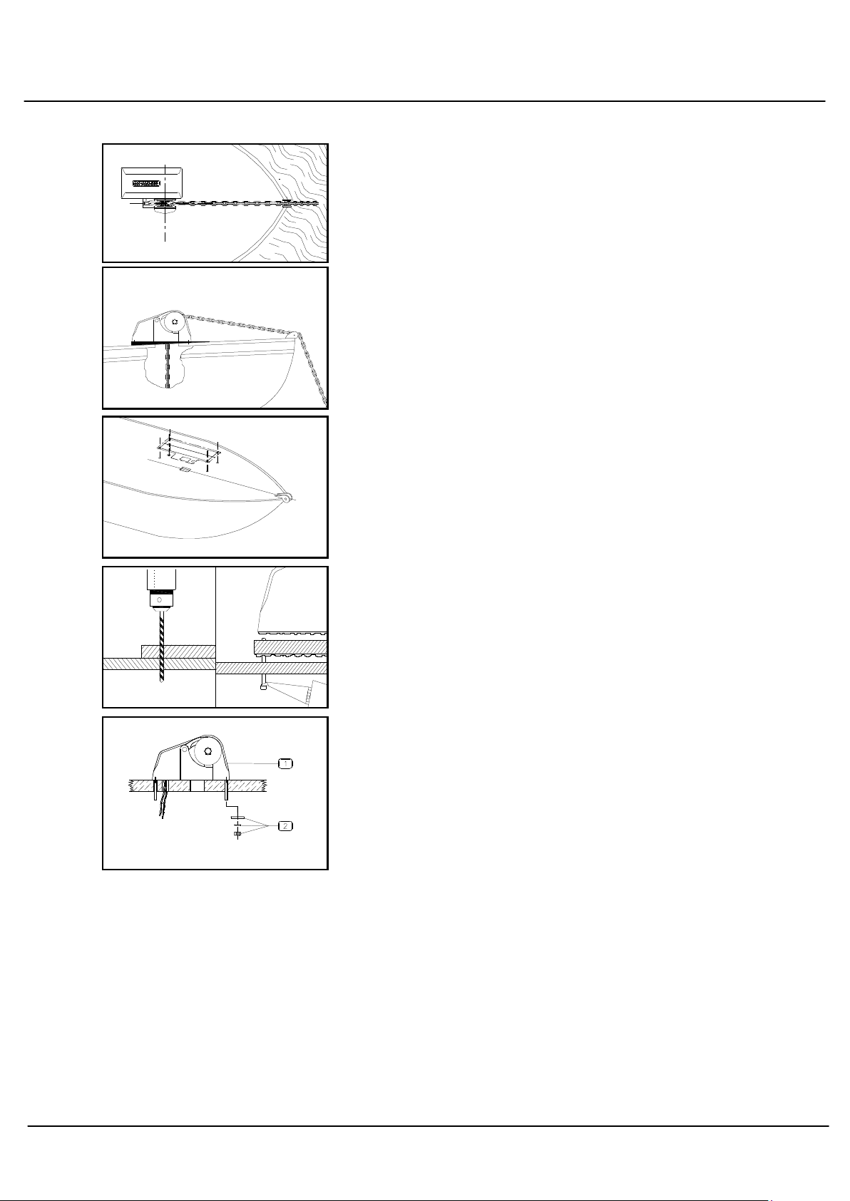
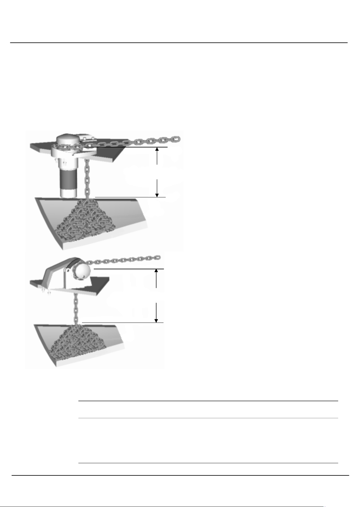
It is a common mistake to locate the windlass too far forward, or too close to the bulk head,
where there is insufficient room for chain and anchor stowing. The chain fail position should
be in the centre of the chain locker. If the chain falls alongside a bulkhead or onto the stem it
will pyramid and jam.
If the chain falls into an undesirable position, a metal tube can be fitted under the hawser to
redirect the chain to a preferred position. This pipe should be at least ½ times the diameter
of the chain. It should also have as much vertical angle as possible. Position the windlass in
the best location with the chain hawser facing forward. Ensure sufficient room to run electric
cables to the windlass. Follow the instructions on page 4 including underdeck stiffening, deck
camber, alignment, mounting blocks and sealing procedures. The gearbox and motor can
be located in one of 22 positions.
ELECTRICAL
See Wiring Diagrams for wiring instructions.
A c rcu t breaker
must be f tted to ensure warranty
. If the windlass is overloaded or stalled the
circuit breaker automatically cuts off power to the windlass and protects the wiring and
motor. The circuit breaker should not be used as an isolating switch.
Deck Sw tches
are best located out to either port or starboard or directly behind the windlass
in a position where it can be easily reached with your foot or knee, preferably where you can
view the anchor and chain coming aboard
.
Isolat ng Sw tch
should be fitted in an accessible position for safety, ideally close to the
battery or switches. The isolating switch is not a circuit breaker
.
Batter es
are best located as close to the windlass as possible. If located within 7m (23') use a
cable of min 36sqmm, 8mm(5/ 6") core. For longer runs, 9- 7m (30'-55') use 50 sqmm, 0-
2mm (3/8" -7/ 6") core. The larger the cable, the greater voltage is delivered to the motor
and overheating will not occur. Small diameter cables drop voltage considerably
.
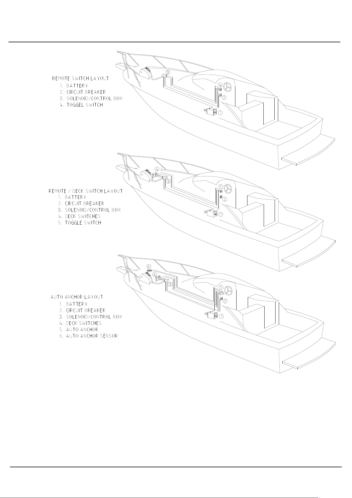
Rotat on
:
Windlasses may be wired for single or dual direction, using single or dual deck
switches for raising or lowering. Alternatively a remote control solenoid packages with Toggle
Switch, Hand Pendant or Auto Anchors are available
.
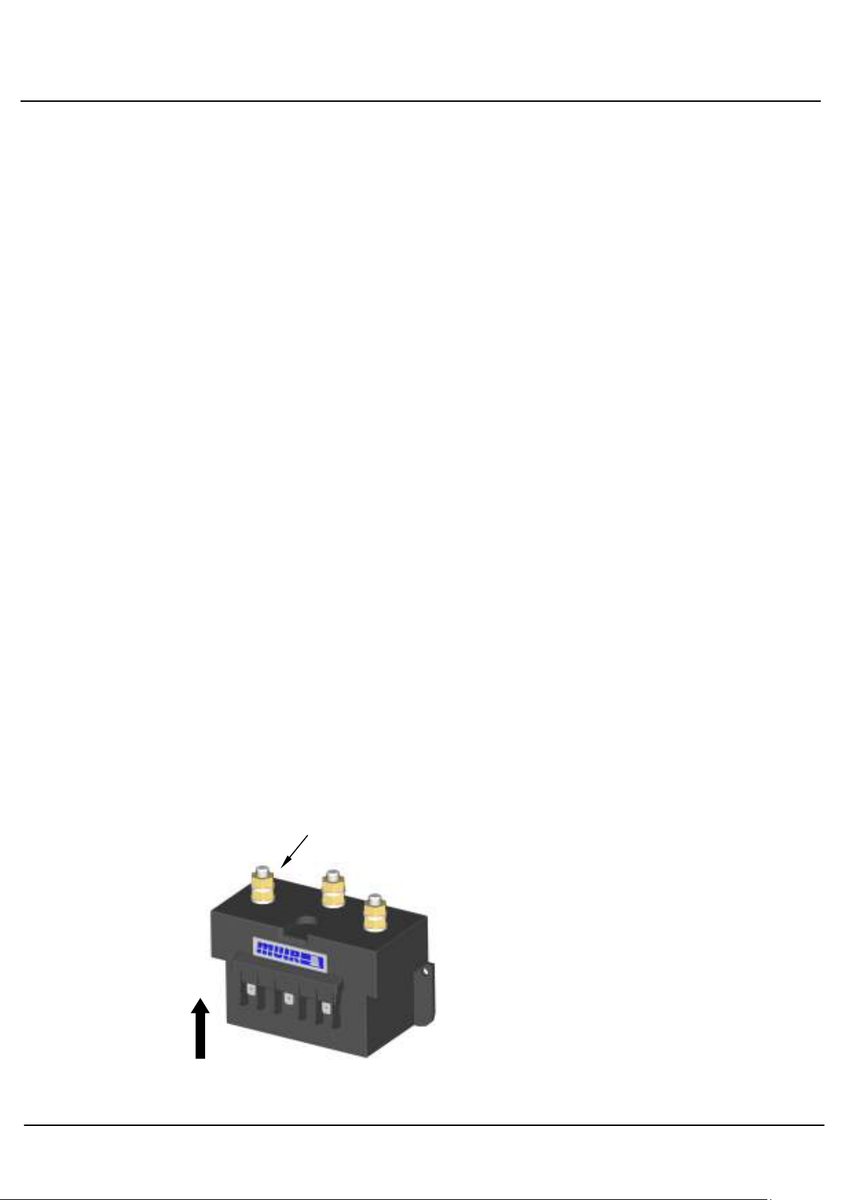
Th s way up
3 POLE
Soleno d Installat on
We recommend that the solenoid is
installed in an upright position, and in
close proximity to the electric motor of
the capstan. The solenoid must not be
installed in chain locker. It should be
located in dry area only.
For wiring information, please refer to the
appropriate wiring diagram listed in the
table below.