4NOTE: DIAGRAMS & ILLUSTRATIONS NOT TO SCALE.
Figure 2
Whenlocatingthefireplace,considerationmust
be given to combustibles and final finishing.
See Figure 18 and confine the final location
of combustible finish materials to the "Safe
Zone". Also refer to Clearance Specifications
on page 6.
Consider the effects of heat when locating
any object in front of or near the fireplace
opening.
PRE-INSTALLATION NOTES
The fireplace may be installed directly on a
combustible floor or raised on a platform of an
appropriate height. Do not place the fireplace
on vinyl or other soft floor coverings. It may,
however, be placed on flat wood, plywood,
particle board or other hard surfaces.
Position the electrical junction box as detailed
in LOCATION OF FIREPLACE. (The umbilical
cord is 9 feet long).
Be sure the fireplace rests on a solid continu-
ous floor or platform with appropriate framing
for support.
The fireplace may be positioned and then the
framing built around it, or the framing may be
constructed and the fireplace positioned into
the opening.
Usually, no special floor support is needed for
the fireplace, however, to be certain:
1.Estimate the total weight of the fireplace sys-
temincluding surroundmaterialssuchasbrick,
stone,etc.,tobeinstalled. Shippingweightsfor
the fireplace may be found on page 8.
2.Measurethe squarefootageofthefloorspace
to be occupied by the system, surrounds and
hearth extensions.
3. Note the decking construction, i.e. 2 x 6’s,
2 x 8’s or 2 x 10’s, single or double joists, type
and thickness of floor boards.
4. Use this information and consult your local
building code to determine if you need ad-
ditional support.
If you plan to raise the fireplace and hearth
extension, build the platform assembly then
position fireplace and hearth extension on
top. Secure the platform to the floor to prevent
possible shifting.
ASSEMBLY STEPS
Note: The following steps represent the normal
sequence of installation. Each installation is
unique, however, and might require a different
sequence.
1. Position firebox prior to framing or into
prepared framing (non-combustible framing
is recommended).
2.Positiontheelectricaljunctionboxas detailed
in LOCATION OF FIREPLACE.
(The umbilical cord is 9 feet long).
3.Waterproofthefireplaceorinstallthe optional
drip pan (see Waterproofing The Fireplace and
Figure 3 on page 5 ).
4.Plumbgasline.(Gasconnectionsshouldonly
beperformedbyanexperienced,licensed/certi-
fied tradesman.)
5. Complete the installation, finish wall mate-
rial, surround and hearth extension to your
individual taste.
6. Assemble and attach optional accessories.
Study the three dimensional illustration (Fig-
ure 1 ) to get a general idea of each element
of your fireplace system.
WATERPROOFING THE FIREPLACE
Although the fireplace is designed to operate
safely outdoors, rain may enter the hearth area,
condensation and can cause water to collect
inside the fireplace bottom.
To prevent water collection, the builder must
provide a means to drain water from under
the fireplace by building or installing a water
collector of the builders choice, before posi-
tioning the fireplace in its location.
Special care must be taken when the fireplace is
installed against an exterior wall. The enclosure
surrounding the fireplace on the sides and back
must be treated as an exterior wall.
Lennox does provide an optional drain pan to
assist weatherproofing the fireplace.
H4651 DPSS36 Drain Pan for E36ODG, H4652
DPSS42 Drain Pan for E42ODG.
ASSEMBLY OUTLINE
Before You Start
Check your inventory list to be sure you have
all the necessary parts supplied in good us-
able condition. Check also for any concealed
damage.
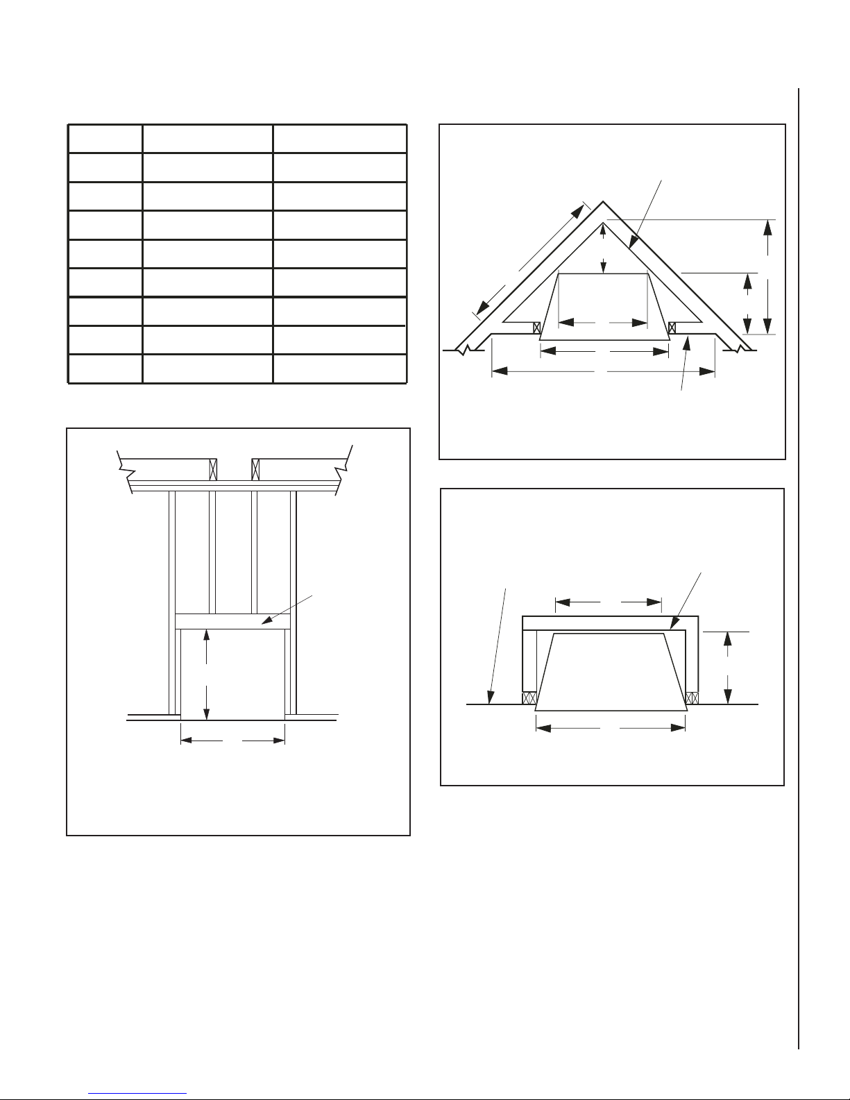
LOCATION OF FIREPLACE
Carefully select the proper location for any
obstructions, clearance to side wall(s), air
availability, locationandaesthetics.Withproper
pre-planning,a slightadjustmentof afewinches
can save considerable time and expense later
during construction and assembly. See Figure
2for some examples.
When choosing a location, care must be taken
to avoid places where flooding or running water
may be a problem.
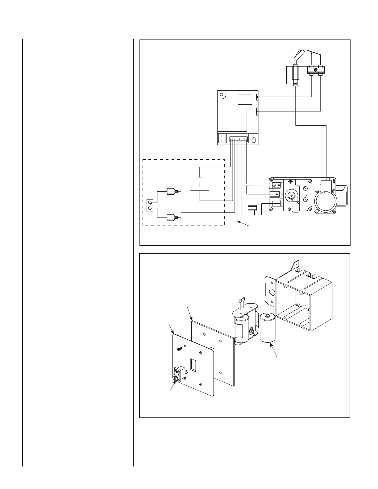
Identify the desired location for the battery
pack/ON/OFFswitch junction box location. This
should be easily accessible and convenient for
use and high enough on the wall to be protected
from water and drifted snow.
Do not use these appliances if any part of
the gas supply, control or burner has been
submerged under water. Immediately call a
qualified, professional service technician to
inspect the appliance and to replace any parts
of the control system and any gas control which
have been under water.
Carefully consider the position of the fireplace
opening with respect to the location of adjacent
ornearbystairwells,doors, windows,walkways
and over hanging trees, patios and wires.
LIVING SPACE
PATIO
Optional
Hearth
Extension