2NOTE: DIAGRAMS & ILLUSTRATIONS NOT TO SCALE.
These appliances are designed to operate
on natural or propane gas only.
CONGRATULATIONS!
In selecting this LENNOX Outdoor Gas Appliance you have chosen the finest and most
dependable fireplace to be found anywhere. A beautiful, prestigious, alternative to a
woodburning fireplace. Welcometo aFamily oftens ofthousands ofsatisfied LENNOX
Fireplace Owners.
Please read and carefully follow all of the instructions found in this manual. Please pay
special attention to the safety instructions provided in this manual. The Homeowner's
Care and Operation Instructions included here will assure that you have many years of
dependable and enjoyable service from your LENNOX product. GENERAL INFORMATION
Note:Installationandrepairshouldbeperformed
by a qualified service person. The appliance
shouldbeinspected annually by a qualifiedpro-
fessional service technician. More frequent in-
spectionsandcleaningsmayberequireddueto
excessive lint from carpeting, bedding material,
etc. It is imperative that the control compart-
ment, burners and circulating air passage ways
of the appliance be kept clean.
S'assurer que le brùleur et le compartiment
des commandes sont propres. Voir les in-
structions d'installation et d'utilisation qui
accompagnent l'appareil.
Provideadequateclearancesaroundairopen-
ings and adequate accessibility clearance for
service and proper operation. Never obstruct
the front openings of the appliance.
Duetohightemperaturestheapplianceshould
be located out of traffic and away from furni-
ture and draperies. Locate furniture and win-
dow coverings accordingly.
TABLE OF CONTENTS
Introduction............................................ page 2
General Information................................ page 2
Operation/Care of Your Appliance .......... page 3
Variable Flame Adjustment ..................... page 4
Glass Cleaning........................................ page 4
Maintenance ........................................... page 4
Maintenance Schedule............................ page 5
Front Glass Enclosure Panel,
Removal and Installation ...................... page 6
Burner Adjustments................................ page 6
Flame Appearance and Sooting .............. page 6
Adjustment ............................................. page 6
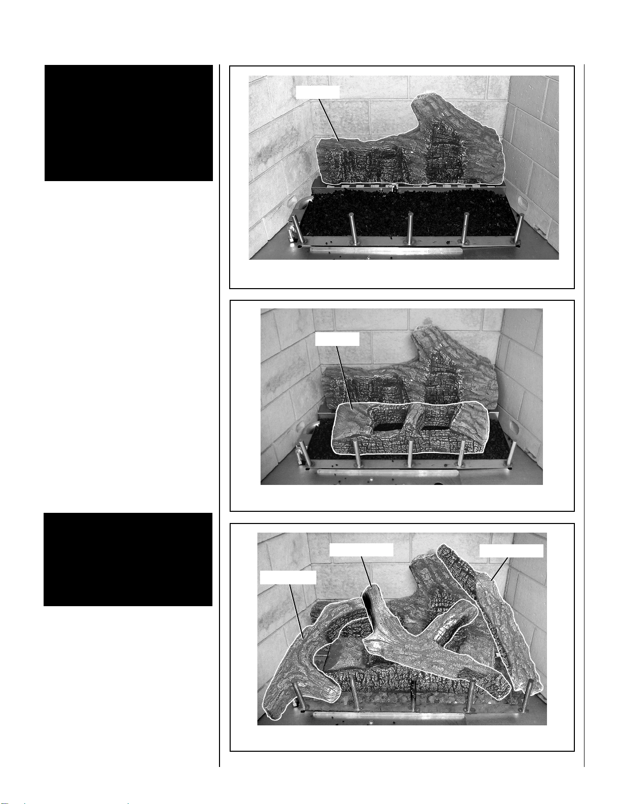
Log Placement........................................ page 6
Millivolt Appliance Checkout................... page 8
Electronic Appliance Checkout ............... page 8
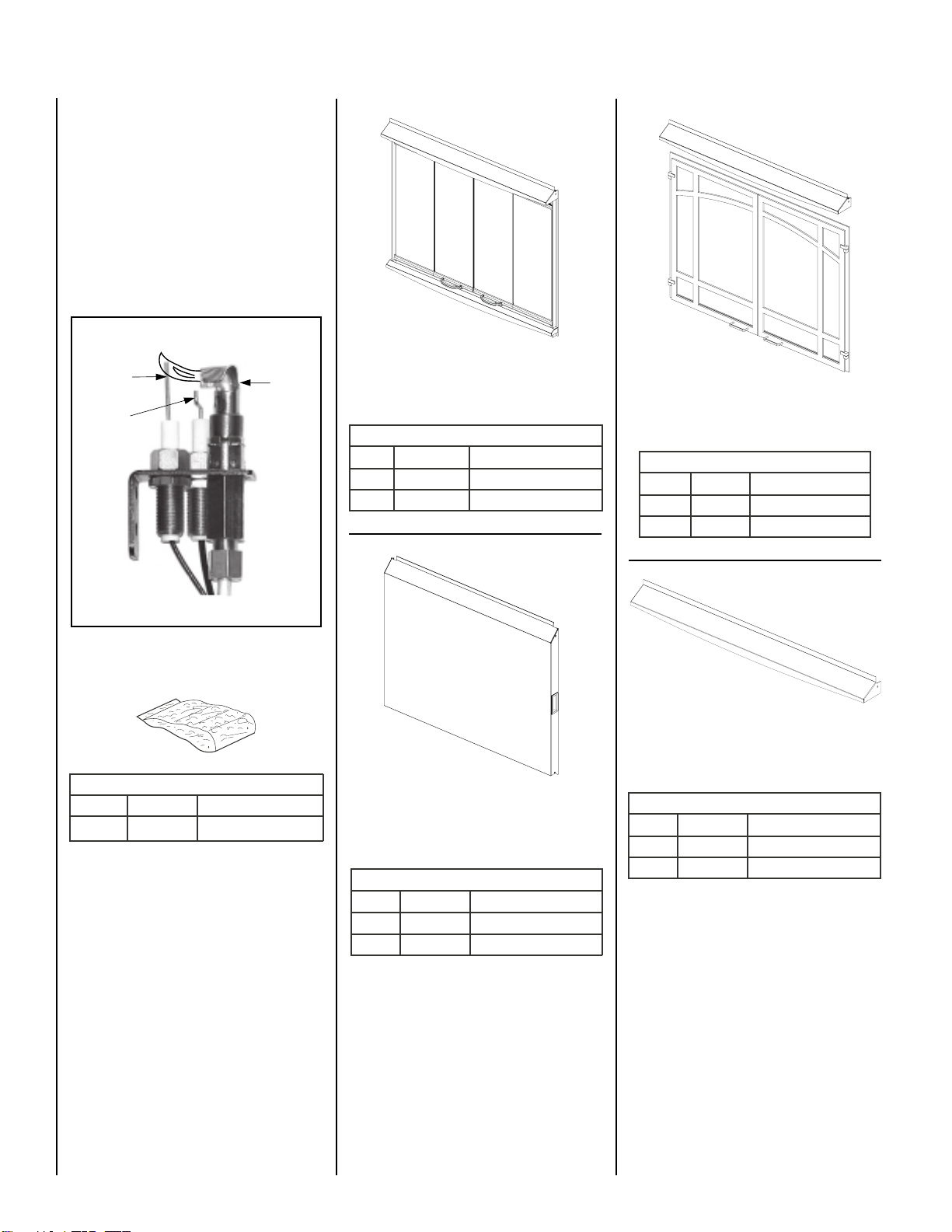
Accessory Components.......................... page 8
Wiring Diagrams .................................... page 9
Warranty................................................. page 9
Replacement Parts ................................. page 9
Product Reference Information .............. page 9
Lighting Instructions –Electronic........... page 10
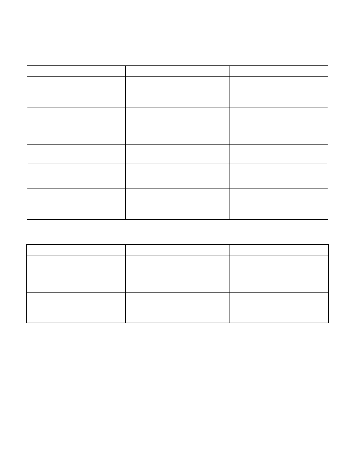
Troubleshooting Guide –Electronic ......... page 12
Replacement Parts List ........................... page 14
WARNING: THESE FIREPLACES ARE
GAS FIREPLACES. DO NOT BURN
WOODOROTHERMATERIAL IN THESE
APPLIANCES.
WARNING:IMPROPERINSTALLATION,
ADJUSTMENT,ALTERATION,SERVICE
ORMAINTENANCECANCAUSEINJURY
OR PROPERTY DAMAGE. REFER TO
THIS MANUAL. FOR ASSISTANCE OR
ADDITIONALINFORMATION CONSULT
A QUALIFIED INSTALLER, SERVICE
AGENCY OR THE GAS SUPPLIER.
TheseappliancescomplywithNationalSafety
Standards and are tested and listed by Omni
Test Laboratories (Report No. 116-F-41-5) to
CSA 4-96 (in Canada, CR97-003), and CAN/
CGA-2.17-M91inbothUSAandCanada,asan
outdoor gas fireplace.
TheInstallationmustconformtolocalcodes
or, in the absence of local codes, with the
NationalFuel Gas Code, ANSI Z223.1/NFPA
54
, or the
Natural Gas and Propane Instal-
lation Code, CSA B149.1
. The appliance,
when installed, must be electrically
grounded in accordance with local codes
or, in the absence of local codes, with the
National Electrical Code, ANSI/NFPA 70
, or
the
Canadian Electrical Code, CSA C22.1
.
DO NOT ATTEMPT TO ALTER OR MODIFY
THECONSTRUCTIONOFTHEAPPLIANCEOR
ITS COMPONENTS. ANY MODIFICATION OR
ALTERATION MAY VOID THE WARRANTY,
CERTIFICATIONANDLISTINGSOFTHISUNIT.
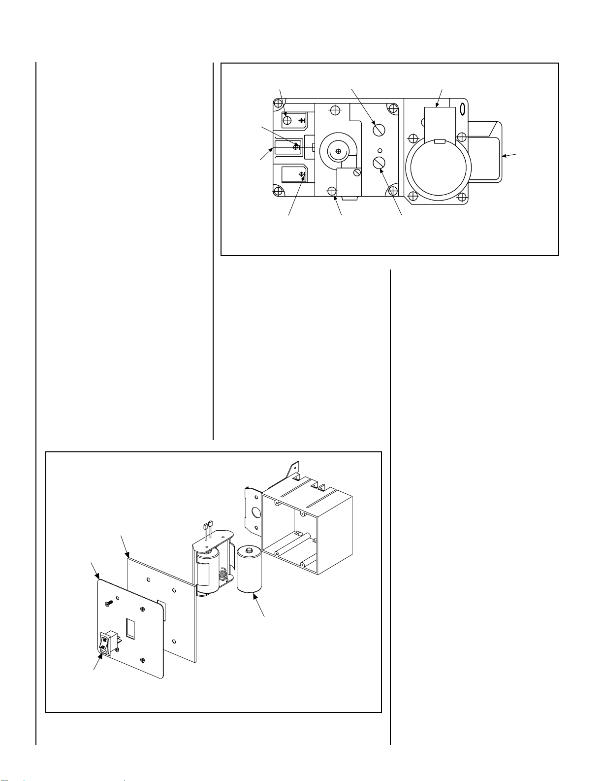
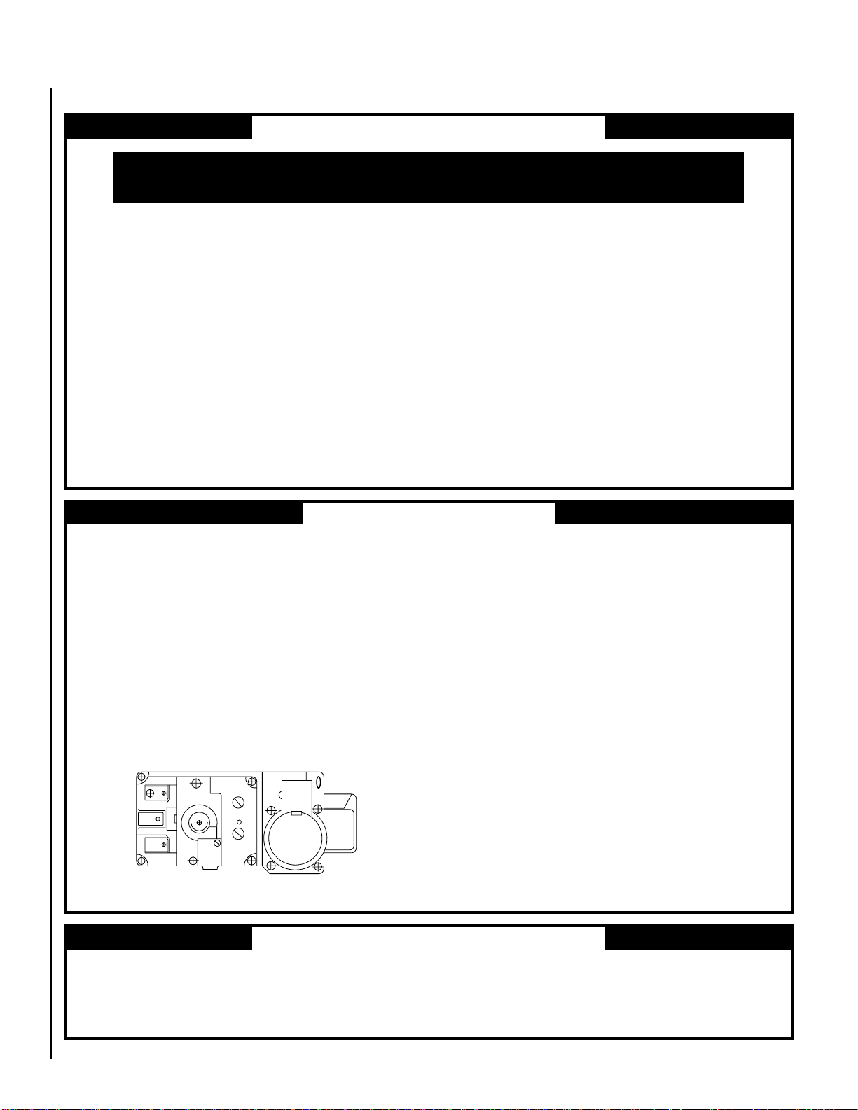
These appliances are designed to operate on
naturalorpropanegas.Anelectronicintermit-
tent pilot ignition system provides safe, effi-
cient operation. The system operates on two
(2) "D" batteries.
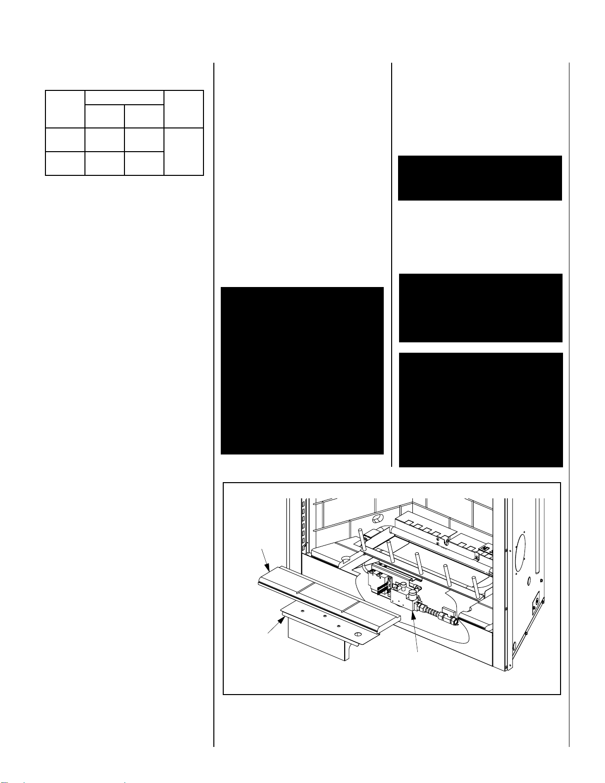
evlaVsaGdetaludoM-yllaunaMhtiwsledoM saGlarutaNsaGenaporP
.oNledoM tupnI etar )H/UTB( .oNledoM tupnI etar )H/UTB(
GDO63E 000,05 ot 005,93 GDO63E 000,64 ot 000,73
GDO24E 000,05 ot 005,93 GDO24E 000,64 ot 000,73
All Models -
All models have a manually modulated gas
valve. Input of these models is shown in the
following table:
WARNING: THESE APPLIANCES ARE
NOT DESIGNED OR INTENDED TO BE
USED FOR COOKING. DO NOT BAR-B-
QUE, HEAT FOOD, OR ROAST MARSH-
MALLOWS IN THIS APPLIANCE. DO-
ING SO COULD DAMAGE THE APPLI-
ANCE AND CAUSE INJURY.
INTRODUCTION
The Fireplace models covered in this manual
are ventless outdoor gas fireplace heaters
designed for exterior application. Ventless
appliancesoperatewiththecombustioncham-
ber completely open to the outside atmo-
sphere. All air for combustion is brought in
through the face opening and exhaust gases
are vented through the same face opening.
Theseappliancesmustbeinstalledoutdoors.
The Lennox Elite®Series Outdoor Gas Fire-
placeisdesignedforoutdooruse. Itmayalso
be installed in screened porches and lanais
that meet these minimum requirements:
Minimum porch area - 96 square feet
Minimum ceiling height - 7 feet 8 inches
A minimum of two (2) walls can be screened
but must be open to outside ventilation.
Minimum screen area - 64 square feet
Minimum screen top height - 6 feet 8 inches