manuals.online logo
Brands
  1. Home
  2. •
  3. Brands
  4. •
  5. Lennox
  6. •
  7. Chiller
  8. •
  9. Lennox EcoLean EAC0091S User manual

Lennox EcoLean EAC0091S User manual

Other manuals for EcoLean EAC0091S

2

This manual suits for next models

33

Other Lennox Chiller manuals

Lennox ECOLEAN EAC Series User manual

Lennox

Lennox ECOLEAN EAC Series User manual

Lennox CLIMATIC 60 User manual

Lennox

Lennox CLIMATIC 60 User manual

Lennox CLIMATIC 60 User manual

Lennox

Lennox CLIMATIC 60 User manual

Lennox CLIMATIC 50 User manual

Lennox

Lennox CLIMATIC 50 User manual
Lennox INNOVA DHADC Series User guide

Lennox

Lennox INNOVA DHADC Series User guide

Lennox CLIMATIC 50 User manual

Lennox

Lennox CLIMATIC 50 User manual

Lennox CLIMATIC 50 User manual

Lennox

Lennox CLIMATIC 50 User manual

Lennox MCW 192 P User manual

Lennox

Lennox MCW 192 P User manual

Lennox CLIMATIC 50 User manual

Lennox

Lennox CLIMATIC 50 User manual

Lennox ECOLOGIC Series Instruction manual

Lennox

Lennox ECOLOGIC Series Instruction manual

Lennox GAH 020S Installation guide

Lennox

Lennox GAH 020S Installation guide
Lennox ECOLEAN EAC Series User manual

Lennox

Lennox ECOLEAN EAC Series User manual

Lennox eCOMFORT R32 GAC 035S User manual

Lennox

Lennox eCOMFORT R32 GAC 035S User manual

Lennox WA Series User manual

Lennox

Lennox WA Series User manual

Lennox 71 SK MCW User manual

Lennox

Lennox 71 SK MCW User manual

Lennox MCC Series User manual

Lennox

Lennox MCC Series User manual

Lennox CWC 2P Series User guide

Lennox

Lennox CWC 2P Series User guide
Lennox MWC 180 User guide

Lennox

Lennox MWC 180 User guide

Lennox CWC 070 2P Instruction Manual

Lennox

Lennox CWC 070 2P Instruction Manual
Popular Chiller manuals by other brands

Trane RTAA-70 Installation & maintenance guide

Trane

Trane RTAA-70 Installation & maintenance guide

Carrier Omnizone 50BVC Installation, Start-Up, Service and Controls Operation and Troubleshooting

Carrier

Carrier Omnizone 50BVC Installation, Start-Up, Service and Controls Operation and Troubleshooting

York YGWH 115 Installation, commissioning & operation

York

York YGWH 115 Installation, commissioning & operation

Galletti PERFORMA MPE Series Technical manual

Galletti

Galletti PERFORMA MPE Series Technical manual

SMC Networks HRR Series manual

SMC Networks

SMC Networks HRR Series manual

Daikin EWAQ016CAW Installation and operation manual

Daikin

Daikin EWAQ016CAW Installation and operation manual

Trane CVHE Troubleshooting

Trane

Trane CVHE Troubleshooting

Moffat Friginox TSR-11SC Specification sheet

Moffat

Moffat Friginox TSR-11SC Specification sheet

Gree GWH07AGA-K6DNA1C Service manual

Gree

Gree GWH07AGA-K6DNA1C Service manual

MP Systems PURGE Series manual

MP Systems

MP Systems PURGE Series manual

Penguin COLD THERAPY CHILLER owner's manual

Penguin

Penguin COLD THERAPY CHILLER owner's manual

Telemark TVP-2000 Operation, installation and service manual

Telemark

Telemark TVP-2000 Operation, installation and service manual

TICA MINI VRF CHR Series Installation & operation manual

TICA

TICA MINI VRF CHR Series Installation & operation manual

MAXA A68 Installation and operation manual

MAXA

MAXA A68 Installation and operation manual

AERMEC NRL FC 2000 installation manual

AERMEC

AERMEC NRL FC 2000 installation manual

SABROE ChillPAC operating manual

SABROE

SABROE ChillPAC operating manual

Aqua Optima Corona Instructions for use

Aqua Optima

Aqua Optima Corona Instructions for use

Nordcap SKF 5 GN 1 manual

Nordcap

Nordcap SKF 5 GN 1 manual

manuals.online logo
manuals.online logoBrands
  • About & Mission
  • Contact us
  • Privacy Policy
  • Terms and Conditions

Copyright 2025 Manuals.Online. All Rights Reserved.

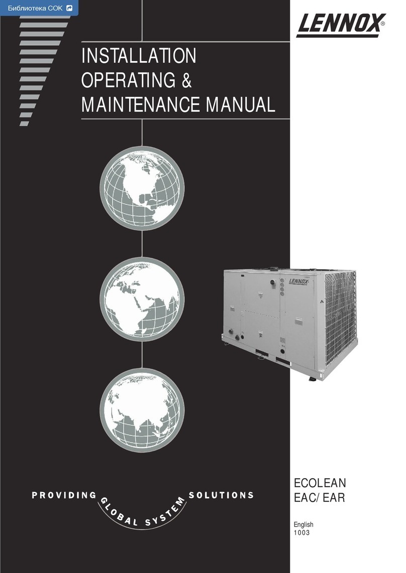
INSTALLATION
OPERATING &
MAINTENANCE MANUAL
ECOLEAN
EAC/EAR
English
1003
Библиотека СОК All manuals and user guides at all-guides.com
all-guides.com
All manuals and user guides at all-guides.com
1
The specifications and technical characteristics in this booklet are given for information purposes. The manufacturer reserves the right to modify them without prior
notice or obligation to modify in a similar manner, the equipments previously supplied.
TABL OF CONT NTS
1.- G N RAL CHARACT RISTICS PAG
PAG 3
DATA PAG FOR UNIT COMMISSIONING
1.1.- T CHNICAL DATA
1.2.- L CTRICAL DATA
1.3.- COMPON NT
1.4.- OP RATION LIMITS
1.5.- PR SSUR DROP IN TH WAT R SYST M
1.6.- HYDRAULIC SYST M DATA
1.7.- SAF TY D VIC S
1.8.- PIPING DRAWINGS
1.9.- DIM NSIONS
1.10.- OPTIONS
4-5
6-8
9
10-11
12-13
14
15-16
17-20
21-24
25-26
2.- INSTALLATION PAG
PAG
3.- COMMISSIONING AND OP RATION
PAG
4.- MAINT NANC
27
27
28
29
30-31
32
2.1.- SIT AND SHIPPING GUIDANC
2.2.- UNIT LIFTING
2.3.- ANTIVIBRATION MOUNTING
2.4.- INSTALLATION CL ARANC S
2.5.- UNIT INSTALLATION
2.6.- L CTRICAL CONN CTIONS
33
34
35
3.1.- ST PS TO FOLLOW FOR COMMISSIONING TH UNITS
3.2.- CH CKING TH WAT R FLOW RAT
3.3.- CORROSION R SISTANC OF COPP R AND STAINL SS ST L OF PLAT S XCHANG R
4.1.- PR V NTIV MAINT NANC
4.2.- CORR CTIV MAINT NANC
4.3.- FAILUR DIAGNOSIS
36
37
38
PAG 2
PR FAC
Our company is a member of the urovent Certification Programme.
The coLeanTM range of Lennox chillers are tested and rated in accordance
with the urovent certification program.
Our company's products comply with uropean standards.
The manufacturing of coLeanTM answers to ISO9001 control quality system.
Lennox have been providing environmental solutions since 1895, our range of coLeanTM reversible chillers continues
to meet the standards that have made L NNOX a household name. Flexible design solutions to meet YOUR needs
and uncompromising attention to detail. ngineered to last, simple to maintain and Quality that comes as standard.
Information on local contacts at www.lennoxeurope.com.
All the technical and technological information contained in this manual, including any drawing and technical descriptions
provided by us, remain the property of Lennox and must not be utilised (except in the operation of this product),
reproduced, issued to or made available to third parties without the prior written agreement of Lennox.
Cod : MIL76E-1003 / 02-2004
All manuals and user guides at all-guides.com
2
FOR N TH RLAND: the ST K logbook, including the
required certificates will be handed over by the
installation technician or left with the machine following
commissioning by Lennox. The data published in this
manual is based on the most recent information available.
It is supplied conditional to later modifications. We reserve
the right to modify the construction and/or design of our
coLean chillers, at any time, without prior notification
or obligation to adapt previous supplies accordingly.
Any work on the Chiller should be carried out by
trained and licensed competent technician.
The following risks are present on the unit:
- risk of electrical shock
- risk of injury from rotating parts
- risk of injury from sharp edges and heavy
weight
- risk of injury from high pressure gas
- risk of injury from high and low temperatures
components
Text Important general instructions
Danger of damage to the chiller
PR FAC
lease read this operating manual prior to
commissioning the EcoLean chiller. Familiarize
yourself with the operation and control of the
EcoLean chiller and closely follow the instructions.
We would like to stress the importance of training with
respect to the correct handling of the chiller. Please
consult Lennox on the options available in this field.
It is important that this manual be stored in a permanent
location in the vicinity of the coLean chiller. For the
sake of clarity, important items in this manual are shown
as follows:
This manual contains important instructions regarding
the commissioning of the coLean chiller. It also
includes important instructions to prevent personal injury
and damage to the machine during operation.
Furthermore, in order to promote fault-free operation of
the chiller, maintenance information has been included.
Please do not hesitate to contact one of our employees
should you require further information on specific chiller
subjects.
Order related documentation will be forwarded under
separate cover. This documentation consists of:
- CE declaration
- Operating manual for control system
- Installation Operating manual
- Wiring diagram
- Unit detail are given on unit nameplate
All manuals and user guides at all-guides.com
3
UNIT: S RIAL No.:
INSTALLATION ADDR SS:
INSTALL R: INSTALL R T L.:
CHECKS:
SUPPLY VOLTAG :
DATA IN UT:
ºC
DAT OF COMMISSIONING:
INSTALL R ADDR SS:
RAT D VOLTAG OF TH UNIT:
ºC
ºC
CONTROL PAN L ID NTIFICATION COD
Compressor 1
Fan 1
Compressor 1
Fan 1
(Amp.)
ºC
ºC
ºC
HYDRAULIC CONN CTION
PURG D OF TH INSTALLATION
Compressor 2
Fan 2
Compressor 2
Fan 2
Air Input Temperature, Coil:
YES NO
G N RAL POW R SUPPLY CONN CTION
CONTROL PAN L CONN CTION (OPTION)
COOLING CYCL H ATING CYCL
Water Output Temperature:
Water Input Temperature:
High Pressure:
Low Pressure:
Options Installed:
COMPR SSOR OIL L V L INDICATOR
UNIT ON RUBB R ANTIVIBRATION MOUNTS
ELECTRIC OWER CONSUM TION
Comments:
Air Input Temperature, Coil:
Water Output Temperature:
Water Input Temperature:
High Pressure:
Low Pressure:
Compressor 3
Compressor 3
DATA PAG FOR UNIT COMMISSIONING
All manuals and user guides at all-guides.com
4
20,6 23,6 27,0 29,6 33,03,0 3,0 3,4 4,0 5,5 6,0 6,5 8,2 9,5 12,0 14,0 17,6
3,1 3,1 5,03,9 6,5 9,0 10,56,2 7,0 12,4 14,0 18,0 21,0
*** Only in units with Hydronic module
* Cooling capacity: Outside temperature: 35ºC / Inlet/outlet water temperature: 12/7ºC
** Heating capacity: Outside temperature: 7ºC DB / 6ºC WB / Inlet/water outlet temperature: 40/45ºC
TYP OF UNIT coLeanTM
WAT R COOL R
A C 035 1 S K HY FP
APPROXIMAT LY CAPACITY IN Kw
NUMB R OF COMPR SSORS
C: COOLING ONLY UNITS
R: H AT PUMP UNITS
K; UNITS R-407C
A; UNITS R-22 (*1)
TYP OF COMPR SSOR-S:SCROLL
--- : Standard version
HY: Hydraulic version
HN: Hydronic version
High static pressure models:
FP: Version models 0091 to 0211
FP1: Version models 0251 to 1303
FP2: Version models 0251 to 1303
(*1) R22 is only for units used outside the C.
1.- G N RAL CHARACT RISTICS
1.1.- T CHNICAL DATA
H AT PUMP
COOLING ONLY
EAC MODELS
Compressor
Hydraulic connections
Min. water rate
Cooling capacity (*)
Refrigerant R-407C
Net weight
1203
S
1303
S
1003
S
1103
S
0812
S
m3/h
.
1 / Scroll
2"G
75,5
10,39
670
700
740
90,0 101,0 114,5 127,0
21/2"G 21/2"G 21/2"G 21/2"G
12,38 13,90 15,76 17,48
803
843
843
948
988
988
1059
1099
1099
1104
1144
1144
Standard
F -F 1
F 2
Nr./Type:
kW.
kg.
kg.
kg.
kg.
0091
S
1"G
8,8
1,21
147
156
---
0111
S
1"G
11,1
1,53
155
173
---
0151
S
1"G
13,3
1,83
168
186
---
0191
S
1"G
17,3
2,38
181
199
---
0211
S
1"G
19,1
2,63
245
263
---
0251
S
1 1/2"G
23,0
3,16
272
297
317
0291
S
1 1/2"G
27,0
3,72
281
296
316
0351
S
1 1/2"G
32,0
4,40
309
324
344
0431
S
1 1/2"G
38,5
5,30
345
360
380
0472
S
2"G
44,0
6,05
540
590
630
0552
S
2"G
51,4
7,07
551
581
621
0672
S
2"G
62,5
8,60
596
626
666
2 / Scroll 3 / Scroll
Heating capacity (**)
Cooling capacity (*)
EAR MODELS
Compressor
Hydraulic connections
Min. water rate
Refrigerant R-407C
Net weight
1 / Scroll
90,0 101,0 114,5 127,0
21/2"G 21/2"G 21/2"G 21/2"G
10,39
12,38 13,90 15,76 17,48
Standard
F -F 1
F 2
Nr./Type:
m3/h
.
kW.
kg.
kg.
kg.
kg.
kW.
1"G
8,8
9,0
159
---
150
0091
S
1"G
11,1
11,1
176
---
158
0111
S
1"G
17,3
17,5
204
---
185
0191
S
1"G
13,3
13,15
190
---
172
0151
S
1"G
19,1
19,8
268
---
250
0211
S
1 1/2"G
32,0
34,0
332
352
317
0351
S
1 1/2"G
38,5
39,0
368
388
353
0431
S
1 1/2"G
23,0
24,0
302
322
277
0251
S
1 1/2"G
27,0
27,5
301
321
285
0291
S
2"G
44,0
47,5
599
639
549
0472
S
2"G
51,4
54,5
592
632
561
0552
S
2"G
62,5
64,5
642
682
612
0672
S
2"G
75,5
79,0
716
756
685
0812
S
1003
S
1103
S
1203
S
1303
S
2 / Scroll
91,0 102,5 117,0 130,0
3 / Scroll
1,21 1,53 1,83 2,38 2,63 3,16 3,72 4,40 5,30 6,05 7,07 8,60
865
865
825
1011
1011
971
1124
1124
1084
1169
1169
1129
HYDRAULIC VERSION / HYDRONIC VERSION
Expansion
vessel
Buffer tank (***)
ump type:
Security valves
xpansion vessel
SET RESSURE
Multicellular centrifugal pump with one speed
Capacity
Capacity
bar
bar 3
4
5 L
50 L
3
4
5 L
50 L
3
4
5 L
50 L
3
4
5 L
50 L
3
4
12 L
75 L
3
4
12 L
75 L
3
4
12 L
75 L
3
4
12 L
75 L
3
4
18 L
100 L
3
4
18 L
100 L
3
4
18 L
100 L
3
4
18 L
100 L
3
4
5 L
50 L
3
4
35 L
240 L
3
4
35 L
240 L
3
4
35 L
240 L
3
4
35 L
240 L
25,2 28,2 30,5 34,0
All manuals and user guides at all-guides.com
all-guides.com
5
set
mode
on off



set
mode
on off



STANDARD AXIAL FAN UNITS
set
mode
on off



set
set
mode
mode
on of
on of
f



set
set
mode
mode
on of
on of
f



set
mode
on off



set
mode
on off



set
mode
on off



1.- G N RAL CHARACT RISTICS
1.1.- T CHNICAL DATA
23000 21000
2
Air flow
rate
m /h
3
Air flow
rate
m /h
3
Air flow
rate
m /h
3
Air flow
rate
m /h
3
Air flow
rate
m /h
3
Air flow
rate
m /h
3
Air flow
rate
m /h
3
Air flow
rate
m /h
3
Air flow
rate
m /h
3
0351S-F 1 0431S-F 1 0472S-F 1 0812S-F 1 1003S TO 1303S-F 10251S-F 1 0291S-F 1 0552S-F 1 0672S-F 1
Fan number
Fan type
Available
static
pressure
a
MODELS
AVAILABLE STATIC RESSURE U TO 120 a - F 1 VERSION
1
50
75
100
125
11500
9600
7200
8500 8100
6900
9200
1100011500
8500
7200
9600
1,7
1,65
1,55
1,6
1,7
1,6
1,65
1,55
1,65
1,6
1,5
1,55
10500
8800
6600
7700
1,65
1,55
1,6
1,5
17000
14400
19200
3,4
3,3
3,1
3,2
23000
17000
14400
19200
3,4
3,3
3,1
3,2
22000
18400
13800
16200
3,3
3,1
3,2
3
15400
13200
17600
3,3
3,2
3
3,1
Power
input
kW
Power
input
kW
Power
input
kW
Power
input
kW
Power
input
kW
Power
input
kW
Power
input
kW
Power
input
kW
1N~230V
Power
input
kW
900 rpm (Low speed)
3~400V
36000
32000
28000
34000
5
5,1
5,3
5,2
Axial - Direct coupling 1450 rpm
24800 23000
2
Air flow
rate
m /h
3
Air flow
rate
m /h
3
Air flow
rate
m /h
3
Air flow
rate
m /h
3
Air flow
rate
m /h
3
Air flow
rate
m /h
3
Air flow
rate
m /h
3
Air flow
rate
m /h
3
Air flow
rate
m /h
3
0351S-F 2 0431S-F 2 0472S-F 2 0812S-F 2
6800 2,45 6800 2,45 6500 2,45 6250 2,5 4,9 4,9
1003S TO 1303S-F 20251S-F 2 0291S-F 2 0552S-F 2 0672S-F 2
Fan number
Fan type
Available
static
pressure
a
MODELS
AVAILABLE STATIC RESSURE U TO 250 OR 350 a - F 2 VERSION
1
350
150
200
250
300
12400
10800
7800
9200 8800
7500
10400
1190012400
9200
7800
10800
2,45
2,3
2,4
2,3
2,45
2,3
2,3
2,4
2,4
2,3
2,4
2,3
11500
10000
7250
8500
2,35
2,3
2,25
2,45
13600
18400
15600
21600
4,9
4,9
4,6
4,8
4,6
13600
24800
18400
15600
21600
4,9
4,6
4,8
4,6
13000
23800
20800
15000
17600
4,8
4,6
4,6
4,8
12500
17000
14500
20000
5
4,7
4,5
4,9
4,6
Power
input
kW
Power
input
kW
Power
input
kW
Power
input
kW
Power
input
kW
Power
input
kW
Power
input
kW
Power
input
kW
Power
input
kW
3~230V/3~400V
44000
N/A
36000
N/A
40000
1450 rpm (High speed)
3~400V
N/A
9,2
9,3
N/A
9,4
Axial "short case" - Direct coupling 1450 rpm
ower
Input
Fan number
MODELS
Fan type
1003S
Air flow rate
kW
1103S 1203S 1303S
Axial - Direct coupling
32250
3~400V
1+1
High
Low 27250
36250
29250
36000
29000
40000
31000
Low
1,05 + 1,05
High
Low 0,77 + 0,77
2 + 1,05
1,25 + 0,77
2 + 1,05
1,25 + 0,77
2 + 2
1,25 + 1,25
Fan speed rpm 700 + 700
High
550 + 550
900 + 700
700 + 550
900 + 700
700 + 550
900 + 900
700 + 700
m3/h
ower
Input
Fan number
MODELS
Fan type
0091S 0111S 0151S 0191S 0211S 0251S 0291S 0351S 0431S 0472S 0552S 0672S 0812S
Air flow rate
kW
1
11000 10500 19000 23000 22000 21000
3500 6500 6700 6500 6300 9500 11500
0,85 0,83 1,50 1,80 1,70 1,66
0,15 0,30 0,32 0,30 0,28 0,75 0,90
12
Axial - Direct coupling 900 rpm 1N~230V
2
m3/h
2
0211S-F0191S-F0151S-F
Fan number
Fan type
Available
static
pressure
a
MODELS 0111S-F0091S-F
50
100
150
200
HIGH STATIC RESSURE UNITS
AVAILABLE STATIC RESSURE U TO 200 a - F VERSION
Centrifugal - Direct coupling 1450 rpm
1
1N~230V
Air flow
rate
m /h
3
3500
2700
2500
2200
0,9
0,8
0,75
0,7
Power
input
kW
Air flow
rate
m /h
3
6500
5700
5200
4700
6700
Air flow
rate
m /h
3
5900
5400
4900
1,95
1,8
1,65
1,5
Power
input
kW
Air flow
rate
m /h
3
6500
5700
5200
4700
1,9
1,75
1,6
1,45
Power
input
kW
6300
Air flow
rate
m /h
3
5500
5000
4500
1,85
1,7
1,55
1,4
Power
input
kW
1,9
1,75
1,6
1,45
Power
input
kW
set
mode
on off



set
mode
on off



All manuals and user guides at all-guides.com
6
EAC / EAR MODELS
V/f (50 Hz)
Voltage
Maximum
consumption
Compressor kW.
Fan motor kW.
kW.
Total power
Maximum
current
Compressor A
Fan motor A
A
Total current
HYDRAULIC VERSION / HYDRONIC VERSION
Water pump
kW.
A
V/f (50 Hz)
Maximum current
Maximum absorbed power
LRC A
Total current
EAC / EAR MODELS
V/f (50 Hz)
Voltage
Maximum
current
Maximum
consumption
Compressor kW.
Fan motor kW.
kW.
Total power
Compressor A
Fan motor A
A
Total current
LRC A
Total current
A
kW.
V/f (50 Hz)
Water pump
Maximum current
Maximum absorbed power
HYDRAULIC VERSION / HYDRONIC VERSION
0351S 0431S
1003S 1103S 1203S 1303S
1N~230V
3~230V - 3N~400V
1N~230V 3~230V - 3~400V
3~230V - 3N~400V
16,40
0,85
15,55
25,60
44,34
3,50
29,10
47,84
282,50
161,50
1,10
3,00
1,70
20,60
0,83
19,77
29,80
51,61
3,50
33,30
55,11
333,50
192,50
1,10
3,00
1,70
3~230V - 3~400V
3N~400V
3~400V
2,20
---
3,70
2,30
---
3,90
2,50
---
4,20
2,70
---
4,50
set
mode
on off



set
mode
on off



set
mode
on off



1.- G N RAL CHARACT RISTICS
1.2.- STANDARD UNIT L CTRICAL DATA
set
mode
on off



3~230V
3~400V
3~230V
3N~400V
3~230V
3N~400V
3~230V
3~400V
3~230V
3~400V
1N~230V
3~230V
3N~400V
1N~230V
3~230V
3N~400V
1N~230V
3~230V
3~400V
1N~230V
0111S
4,70
0,30
5,00
1,60
17,32
10,00
0,49
99,60
51,60
18,92
11,60
2,30
---
---
---
---
---
0091S
4,05
0,15
4,20
0,80
12,12
7,00
23,10
0,49
95,80
91,80
44,30
12,92
7,80
23,90
2,302,30
---
---
0151S
5,78
0,32
6,10
1,60
21,48
12,40
0,49
134,60
63,60
23,08
14,00
2,30
---
---
---
---
---
0191S
7,60
0,30
7,90
1,60
27,71
16,00
0,72
179,60
97,40
29,31
17,60
2,40
1,40
---
---
---
---
---
0211S
8,62
0,28
8,90
1,60
26,15
15,10
0,72
167,60
95,60
27,75
16,70
2,40
1,40
---
---
---
---
0251S
0,72
11,15
0,75
11,90
3,00
31,17
18,00
119.00
213,00
34,17
21,00
2,40
1,40
---
---
---
---
0291S
0,72
12,90
0,90
13,80
3,50
35,85
20,70
227,50
130,50
39,35
24,20
2,40
1,40
---
---
---
---
--- --- ---
--- ---
---
---
---
---
0472S
23,60
1,50
22,10
36,00
62,35
6,00
42,00
68,35
243,70
138,00
1,17
3,00
1,70
0552S
27,30
1,80
25,50
41,40
71,70
7,00
48,40
78,70
262,70
152,30
1,17
3,00
1,70
0672S
32,60
1,70
30,90
51,20
88,68
7,00
58,20
95,68
324,10
187,00
1,55
4,80
2,80
0812S
39,80
1,66
38,14
59,60
103,22
7,00
66,60
110,22
382,00
222,00
1,55
4,80
2,80
47,7
2,1
45,6
71,2
---
4,8
76
---
----
235,2
54,1
3,1
51
81
---
6,4
87,4
---
---
246,6
59,3
3,1
56,2
91,2
---
6,4
97,6
---
---
282,6
66
4
62
99,2
---
8
107,2
---
---
331,2
All manuals and user guides at all-guides.com
7
set
mode
on off



0251S 0291S 0672S 0812S 0351S 0431S 0472S 0552S
V/f (50 Hz)
EAC / EAR MODELS
Voltage
kW.
V/f (50 Hz)
A
HYDRAULIC VERSION / HYDRONIC VERSION
Water pump
Maximum current
Maximum absorbed power
Maximum
current
Maximum
consumption
Compressor kW.
Fan motor kW.
kW.
Total power
Compressor A
Fan motor A
A
Total current
LRC A
Total current
1203S 1303S1003S 1103S
1,101,10 1,551,551,171,170,720,72
8,00 8,00
39,17 43,85
26,00 28,70
218,00 232,00
135,00
31,17 35,85
18,00 20,70 25,60
44,34
8,00
33,60
52,34
287,00
166,00
29,80
51,61
8,00
37,80
59,61
338,00
197,00
36,00
62,35
16,00
52,00
78,35
253,68
148,00
41,40
71,70
16,00
57,40
87,70
271,66
161,30
51,20
88,68
16,00
67,20
104,68
333,06
196,00
59,60
103,22
16,00
75,60
119,22
390,98
231,00
124,00
3,00 4,802,40 2,40 3,00 3,00 3,00 4,80
1,70 2,801,40 1,40 1,70 1,70 1,70 2,80
12,85 14,60
1,70 1,70
11,15 12,90
34,20 41,44
3,30 3,30
30,90 38,14
28,90
3,40
25,50
25,50
3,40
22,10
21,42
1,65
19,77
17,20
1,65
15,55
3~230V - 3N~400V 3N~400V
3~230V - 3~400V 3~400V
71,20
---
80,80
---
---
240,00
50,60
45,60
81,00
---
90,60
---
---
249,80
56,00
51,00
91,20
---
100,8
---
---
285,80
61,20
56,20
99,20
---
108,8
---
---
332,80
67,00
62,00
5,00 5,00 5,00 5,00
9,60 9,60 9,60 9,60
2,20
---
3,70
2,30
---
3,90
2,50
---
4,20
2,70
---
4,50
set
set
mode
mode
on of
on of
f



set
mode
on off



1.- G N RAL CHARACT RISTICS
1.2.- HIGH STATIC PR SSUR UNIT L CTRICAL DATA F VERSION
0091S 0111S 0151S 0191S 0211S
V/f (50 Hz)
EAC / EAR MODELS
Voltage
Maximum
current
LRC
Compressor A
Fan motor A
A
Total current
A
Total current
Maximum
consumption
Compressor kW.
Fan motor kW.
kW.
Total power
kW.
V/f (50 Hz)
A
HYDRAULIC VERSION / HYDRONIC VERSION
Water pump
Maximum current
Maximum absorbed power
1N~230V
3~230V - 3N~400V
4,00 8,008,008,008,00
16,12 25,32 29,48 35,71 34,15
11,00 18,00 20,40 24,00 23,10
27,10
99,00
95,00 106,00 141,00 186,00 174,00
47,50 58,00 70,00 103,80 102,00
12,12 17,32 21,48 27,71 26,15
7,00 10,00 12,40 16,00 15,10
23,10
4,95
0,90
4,05
10,47
1,85
8,62
9,50
1,90
7,60
7,73
1,95
5,78
6,60
1,90
4,70
0,49
1N~230V
2,30
0,720,720,49
2,30
0,49
2,402,40
2,30
3~230V - 3~400V
1,401,40
--- --- --- ---
--- --- --- ---
--- --- ---
--- --- ---
------
--- --- --- ---
3~230V
3~400V
1N~230V
3~230V
3~400V
1N~230V
3~230V
3N~400V
1N~230V
3~230V
3N~400V
1N~230V
F 1 VERSION
3~230V
3~400V
3~230V
3N~400V
3~230V
3N~400V
3~230V
3~400V
set
mode
on off



All manuals and user guides at all-guides.com
8
set
mode
on off



0251S 0291S 0672S 0812S 0351S 0431S 0472S 0552S
V/f (50 Hz)
EAC / EAR MODELS
Voltage
kW.
V/f (50 Hz)
A
HYDRAULIC VERSION / HYDRONIC VERSION
Water pump
Maximum current
Maximum absorbed power
Maximum
current
Maximum
consumption
Compressor kW.
Fan motor kW.
kW.
Total power
Compressor A
Fan motor A
A
Total current
LRC A
Total current
1203S 1303S1003S 1103S
1,101,10 1,551,551,171,170,720,72
3~230V - 3~400V
8,00 8,00
39,17 43,85
22,50 25,20
218,00 232,00
131,50
31,17 35,85
18,00 20,70 25,60
44,34
8,00
30,10
52,34
287,00
162,50
29,80
51,61
8,00
34,30
59,61
338,00
193,50
36,00
62,35
16,00
45,00
78,35
253,68
141,00
41,40
71,70
16,00
50,40
87,70
271,66
154,30
51,20
88,68
16,00
60,20
104,68
333,06
189,00
59,60
103,22
16,00
68,60
119,22
390,98
224,00
120,50
3,00 4,802,40 2,40 3,00 3,00 3,00 4,80
1,70 2,801,40 1,40 1,70 1,70 1,70 2,80
13,60 15,35
2,45 2,45
11,15 12,90
35,70 42,84
4,80 4,70
30,90 38,14
30,40
4,90
25,50
27,00
4,90
22,10
22,12
2,35
19,77
17,95
2,40
15,55
4,50 4,50 4,50 4,50 9,00 9,00 9,00 9,00
3~400V
3~230V - 3N~400V 3N~400V
71,20
---
---
87,40
---
---
246,60
54,80
45,60
81,00
---
---
97,20
---
---
256,40
60,20
51,00
91,20
---
---
107,40
---
---
292,40
65,40
56,20
99,20
---
---
115,40
---
---
339,40
71,20
62,00
9,20 9,20 9,20 9,20
16,20 16,20 16,20 16,20
2,20
---
3,70
2,30
---
3,90
2,50
---
4,20
2,70
---
4,50
set
set
mode
mode
on of
on of
f



1.- G N RAL CHARACT RISTICS
1.2.- HIGH STATIC PR SSUR UNIT L CTRICAL DATA
F 2 VERSION
3~230V
3~400V
3~230V
3N~400V
3~230V
3N~400V
3~230V
3~400V
3~230V
3~400V
All manuals and user guides at all-guides.com