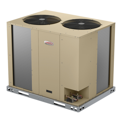
Lennox V8LAC01 User manual

1
©2018 Lennox Industries Inc. Dallas, Texas, USA
INSTALLATION
INSTRUCTIONS
VRF SYSTEMS
507904-01
02/2020
THIS MANUAL MUST BE LEFT WITH THE
OWNER FOR FUTURE REFERENCE
Shipping and Packing List
Check the components for shipping damage. If you nd
any damage, immediately contact the last carrier.
Package 1 of 1 contains one of the following:
Outdoor Unit Low Ambient
Cooling Kit
These instructions are intended as a general guide and do
not supersede local codes in any way. Consult authorities
having jurisdiction before installation.
WARNING
Improper installation, adjustment, alteration, service
or maintenance can cause property damage, personal
injury or loss of life.
Installation and service must be performed by a licensed
professional HVAC installer, service agency or the gas
supplier.
Failure to follow safety warnings and these instructions
exactly could result in property damage, dangerous
operation, serious injury, or death.
Any additions, changes, or conversions required in order
for the appliance to satisfactorily meet the application
needs must be made by a licensed professional HVAC
installer (or equivalent) using factory-specied parts.
Do not use this system if any part has been under water.
A ood-damaged appliance is extremely dan gerous.
Immediately call a licensed professional HVAC service
technician (or equivalent) to inspect the system and to
replace all controls and electrical parts that have been
wet, or to replace the system, if deemed necessary.
WARNING
Before beginning any installation or service work,
disconnect all power from the outdoor unit.
VRF
LAKA
1 - Low Ambient Cooling Hood Assembly (LAKA-1)
1 - Rear Wind Deector (LAKA-2)
2 - Side Wind Deectors (LAKA-3)
1 - Wiring harness and conduit assembly
5 - Wiring conduit mounting brackets
6 - Plastic cable ties
26 - 10-16x1/2” self-tapping screws
1 - Installation and operation manual
LAKB
1 - Low Ambient Cooling Hood Assembly (LAKB-1)
1 - Rear Wind Deector and rear corner panels (LAKB-2)
2 - Side Wind Deectors (LAKB-3)
1 - Wiring harness and conduit assembly
5 - Wiring conduit mounting brackets
6 - Plastic cable ties
48- 10-16x1/2” self-tapping screws
1 - Installation and operation manual

2
Model Number Identication
V 8 LAC 01 - 2 P
Brand/Family
V = Variable Refrigerant Flow (VRF)
Unit Type
8 = VRF Split Heat Pumps and Heat Recovery
Unit Type
01 = 6-10 ton Outdoor Units
02 = 12-16 ton Outdoor Units
Controls Protocol
1 = Phase 1
2 = Phase 2
3 = Phase 3
Voltage
P = 208/230V-1 phase-60hz
Product Description
LAC = Low Ambient Cooling Kit
Application
Lennox VRF Low Ambient Cooling Kits, V8LAC01
and V8LAC02, are to be used with VPB/VRB 6 to
16-ton outdoor units in cold climate applications.
The kits extend cooling operation range from the standard
5°F (-15°C) down to -10°F (-23°C).
CAUTION
As with any mechanical equipment, contact with sharp
sheet metal edges can result in personal injury. Take
care while handling this equipment and wear gloves and
protective clothing.
To ensure proper system performance and reliability,
Lennox does not recommend operation of VRF systems
during any phase of construction. Construction debris,
low temperatures, harmful vapors, and operation of the
unit with misplaced lters can damage the units. Failure
to follow these guidelines will result in the warranty be-
ing voided.
IMPORTANT
The Clean Air Act of 1990 bans the intentional venting
of refrigerant (CFC’s and HCFC’s) as of July 1, 1992.
Approved methods of recovery, recycling or reclaiming
must be followed. Fines and/or incarceration may be
levied for non-compliance.

3
Component Identication
LAKA-1
LAKA-2
Low Ambient Cooling Hood Assembly with Damper &
Control Box (1)
Rear Wind Deector (1)
Side
Wind Deectors (2)
LAKA-3
LAKB-1
LAKB-2
LAKB-3
V8LAC01 V8LAC02
Low Ambient Cooling Hood Assembly with Damper &
Control Box (1)
Rear Wind Deector (1)
Side
Wind Deectors (2)
Rear Corner Channel

4
LAKA (6-10 Ton Outdoor Unit) Dimensions - inches (mm)
LAKA-2 LAKA-3
44-3/8
(1127)
45-5/8
(1159)
14-3/8
(371)
51
(1295)
51
(1295)
23
(584)
24-3/8
(619)
14-3/4
(375)
LAKA-1
31-1/8
(791)
29-1/8
(740)
27-3/4
(705)
55
(1397)
53
(1346)

5
LAKB (12-16 Ton Outdoor Unit) Dimensions - inches (mm)
17-1/8
(435)
34-1/4
(870)
30-1/2
(775)
31-3/4
(806)
72-1/4
(1835)
68-1/8
(1730)
59-3/4
(1518)
61-1/8
(1553)
15-3/8
(391)
56-1/2
(1435)
24-5/8
(625)
23-1/4
(590)
56-1/2
(1435)

6
Installation Clearances - inches (mm)
SINGLE ROW
TWO ROWS
THREE OR MORE ROWS
39 (991)
39 (991)
Front Front
39 (991)
39 (991)
Front Front
39 (991)
39 (991)
Front Front
31 (800)
Air Flow
Air Flow
FrontRear
31 (800)
Air Flow
Air Flow
Air Flow
Air Flow
39 (991)
39 (991)
Front Front
39 (991)
39 (991)
Front Front
31 (800)
Air Flow
Air Flow
Air Flow
Air Flow
Air Flow
Air Flow
39 (991)
Front Front
>12 in. (305 mm)
< 156 in. (3962 mm)
39 (991)
>12 in. (305 mm)
< 156 in. (3962 mm)
>12 in. (305 mm)
< 156 in. (3962 mm)
NOTEs - Discharge air duct will remain free of obstructions at a minimum distance of 18 ft. (5.5 m).
Discharge air shall not be directed toward operable windows or building fresh air intakes.

7
Placement
WARNING
Use the provided and specied components when
installing equipment. Failure to do so may result
in unit falling, water leaking or electrical shocks,
causing personal injury or equipment or property
damage.
Check stability of unit support. If support is not
capable of carrying weight of the unit, unit may fall
causing personal injury or equipment damage.
Consider the possibility of earthquakes in your
area when installing the equipment. If the unit is
not correctly secured, it may fall, causing personal
injury or equipment damage.
Safely dispose of packing materials, which include
nails, wood and other sharp objects, as well as
plastic wrapping. Children playing with plastic
wrap or bags risk the danger of suocation.
Outdoor Unit Positioning Considerations
In addition to clearances, the following items should be
considered when setting the outdoor unit:
• If low ambient cooling hood is applied, the outdoor unit
should be set at medium static pressure mode (40Pa).
Add 12 in. (305 mm) to standard mounting clearances
• Allow sucient space around unit for proper operation
and maintenance.
• Install the unit high enough above the ground or roof to
allow adequate drainage of defrost water and prevent
ice or snow build-up.
• Carefully consider how to manage defrost and
condensate water disposal to prevent ice from creating
hazardous conditions near walkways and egresses.
• Use heated tape on condensate drain line.
• Locate unit so winter prevailing winds do not blow
directly on to the outdoor unit.
• In heavy snow areas, do not locate the unit where
drifting will occur. The unit base should be elevated
above the depth of average snows.
Wind Barrier
Inlet Air
Prevailing Winter Winds
39” (991mm)
Min. Distance
Figure 1. Prevailing Winds Barrier
• Discharge air duct will remain free of obstructions at a
minimum distance of 18 ft. (5.5 m).
• Discharge air shall not be directed toward operable
windows or building fresh air intakes.
• Appliance exhaust such as drier and kitchen exhaust
vents shall maintain a minimum distance of 15 ft.
(4.5 m).
• Outdoor unit shall maintain a minimum distance of 10
ft. (3 m) from fossil fuel lines, gas meters and electri-
cal meters.
• Outdoor unit shall maintain a minimum distance of 10
ft. (3 m) away from plumbing ventilation stacks.
• Outdoor unit should maintain a minimum distance of 3
ft. (1 m) from walkways and emergency exits.
• Outdoor unit shall maintain a distance of 3 ft. (1 m)
away from electrical panels.
• Outdoor unit shall be raised 12 in. (305 mm) above
average snow fall lines.
• Weather resistant equipment supports shall be con-
structed in a manner that will minimize snow or ice
buildup.
• Outdoor unit exhaust and air intakes shall not be ob-
structed with lter material, bird screen or mesh.
• Articial heat shall not be introduced to the outdoor
unit or air intake areas.
IMPORTANT
The equipment supports must elevate the unit at least
12 in. (305 mm) above the maximum expected snow
depth.
8
Figure 2. Direct Hood Discharge Out and Over Enclosure Walls
Minimum
Recommended
Service Clearance
Left (Damper Motor) Side
30 in. (762 mm)
Minimum
Recommended
Service Clearance
Right Side
12 in. (305 mm)
NOTEs - Discharge air duct will remain free of obstructions at a minimum distance of 18 ft. (5.5 m).
Discharge air shall not be directed toward operable windows or building fresh air intakes.
Figure 3. Distance Between Units with Kit Installed

9
Snowfall >12 in. (305 mm)
Additional Rooftop Mounting Guidelines
• The low ambient cooling hood increases the overall
height of the unit and therefore makes it more suscep-
tible to wind stresses. Ensure that unit is secured to
its support using either lag bolts or safety strap. See
Figures 5, 6 and 7.
• Outdoor units should be located in an area protected
from prevailing winds. Hood discharge should be di-
rected away from or perpendicular to the prevailing
winds; never toward prevailing winds.
• Add an additional 12 in. (305 mm) to the standard
mounting clearances. See Page 6.
• For all roof top and other high wind installa-
tions, weather resistant safety straps must
be securely fastened between the discharge
air hood and the equipment support system.
Straps should not be installed where ser-
vice access is impeded or restricted.
Straps should be a minimum 3/16” vinyl coated cable.
See Figures 6 and 7.
• Straps must be attached to the hood where they
will not interfere with the movement of the dampers.
Attachment to both the hood and mounting structure
is to be with a bolt through connection using a bolt ¼”
or larger in diameter.
Weather Resistant
Safety strap
Figure 4. Elevate Unit Above Snow Level
Figure 5. Secure Unit to Weather Resistant Support
Φ 3/8 in (10 mm)
Lag bolt
Figure 6. Secure Unit with Safety Strap (Back)
Due to wind resistant construction, Low ambient cool-
ing kits are better suited for ground level applications.
Should low ambient applications require the outdoor unit
to be installed in elevated areas such as a roof top it is im-
portant to follow all installation guidelines and to observe
local and national equipment fastening guidelines.
Figure 7. Secure Unit with Safety Strap (Sides)
• The outdoor unit and equipment support should be
rmly attached to the structure. Or, if the equipment
support is the type that does not attach to the struc-
ture, refer to the equipment support manufacturer’s
guidelines for proper size and construction.
• Depending on location, exposure and other factors in-
uencing the wind, Additional support (or cables) may
be required.

10
1. Remove rear wire guard from unit and discard. Retain
screws for rear LAKA-2/LAKB-2 wind deector instal-
lation.
2. Remove four side screws from side of the outdoor
unit and retain, use these and 3 provided screws for
LAKA-3/LAKB-3 side deector installation.
Installation
Figure 8. Attach Hood and Wind Deectors Using Provided Screws
CAUTION
AVOID TOUCHING OR DAMAGING COIL SURFACE!
3. Using the provided self-tapping screws, attach hood
assembly and wind deectors to the outdoor unit. Be
sure to level the wind deectors before securing.
4. Install the side screws part way rst and then hang the
wind deector over the coil.
5. Install remaining screws and tighten all screws se-
curely. Repeat with all wind deectors.
6. It is necessary to use self-tapping screws in the out-
door unit cabinet in order to secure the top of each
wind deector. Screw ONLY into the indicated loca-
tions. See Figure 9. No material shall be fastened
to the coil or copper tubing.
Hood
Assembly
Damper
Motor
LAKA/B-3
Left Side
Wind
Deector
LAKA/B-3
Right Side
Wind
Deector
LAKA/B-2
Back
Wind
Deector
Labels are oriented from the Front View. See Figure 11 for Front View.
10-16X1/2”
Self Tapping
Screws
LAKA-2 consists of one back wind deector only as shown in this illustration.

11
Figure 9. Attach Corner Panels LAKB Only Using Provided Screws
LAKB-2
Corner
Guards
LAKB-2
Back
Wind
Deector
LAKB-2 consists of one back wind deector and two corner guards as shown in this illustration.
Hood
Assembly
Damper
Motor
LAKA/B-3
Left Side
Wind
Deector
LAKA/B-3
Right Side
Wind
Deector
Labels are oriented from the Front View. See Figure 11 for Front View.

12
Front Back
Right Side Left Side
Louvers
Damper
Motor
Figure 11. Low Ambient Kit Installed (All Views)
BACK VIEW
SIDE VIEW
Self-tapping
screws allowed in
this section of the
outdoor unit only.
Use caution
when screwing in
the self-tapping
screw. DO NOT
damage coil.
Self-tapping
screws allowed in
this section of the
outdoor unit only.
Use caution
when screwing in
the self-tapping
screw. DO NOT
damage coil.
Figure 10. Field-Made Screw Hole Permitted Locations
Hood
Assembly
LAKA/B-3
Left Side
Wind
Deector
LAKA/B-3
Right Side
Wind
Deector
LAKA/B-2
Back
Wind
Deector
Damper
Motor

13
• Remove the Φ1/2 in. (13 mm) knockout on the wiring
entry panel on the bottom front of the unit as shown
in Figure 12.
• The exible conduit can be routed along the front cor-
ner panel of the unit as shown in Figure 14.
• All conduit, washers and gaskets shall be of weather
resistant and UV rated construction.
• Extremecautionshouldbeusedwhenfasteningconduit
to the outdoor unit cabinet as the coil and copper man-
ifold may be directly behind outer outdoor unit cabinet.
No material shall be fastened to the coil or copper
tubing.
• Once the conduit is secured in place route the wires
up through the bottom compartment and into the top
section of the unit.
• The wires will connect to the main control board as
shown in Figure 13.
Remove Φ1/2 in. (13 mm) knockout
1. Open outdoor unit left-side service panel.
2. Locate outdoor unit control board. Figure 14.
3. Locate CN1 and CN3 connections on the PCB of the
low ambient cooling kit hood damper. Figures 13 & 16.
4. Locate the CN29 connection on the PCB of outdoor
unit. Figure 16.
5. Follow the connection instructions shown in Figure 16.
6. Indicate that the unit has a low ambient kit installed by
either changing the outdoor unit main board dip switch
S9-1 to ON.
7. Set the damper actuator rotation switch at 0. See Fig-
ure 18.
8. Secure any extra or loose wires with plastic zip ties.
Electrical Installation for Kit
WARNING
Before beginning any installation or service work,
disconnect all power from the outdoor unit.
Figure 12. Remove Knockout
Figure 14. Outdoor Unit Control Board Location
Figure 13. Damper Motor Control Board
CN4
4 wires to
damper
actuator
CN1
4 wires from outdoor unit
main control board CN29
CN3
2 wires from outdoor unit
main control board CN29

14
2
Factory switch
positions
1 3 5
Damper Actuator
Y U
Y DC (0) 2...10 V
U DC 2...10 V
AC/DC 24V 50/60Hz
0
1
Low Ambient Baffle Kit Board
Low Ambient Baffle Kit Box
35 2 1
Red Black
White
Orange
0-10V
Input
0-10V
Output AC24V GND CN1
Main borad
Outdoor Unit Main Control Box
Power&Communication BUS
Control Box Mounted on Hood
CN4
CN3
Figure 16. Connection Diagram
1
ON
NOTE - Dip switch handle location is shown as a solid
black box in the table.
Outdoor Unit Main Board S9-1
Low Ambient Kit Installed
Factory default is OFF.

15
P Q
All Drain Wires will connect from outdoor unit chassis to mode selection box chassis at the end of
the signal run.
18 GA., stranded, 2-conductor, shielded control wire (polarity sensitive).
Typical Wiring Diagram, NEC/CEC and Local Codes apply.
Outdoor unit Outdoor unit
(sub1 unit)
Outdoor unit
(sub2 unit)
(PQ)
(main unit)
(PQ)
MS
Box
(PQ)
(PQ)
MS
Box
(PQ)
(PQ)
(H1 H2 ) (H1 H2 ) (H1 H2 )
Outdoor Unit Communication Terminal Block
P Q H1 H2X YO AK1 K2
MS Box Communication
Terminal Block
P Q
Indoor Unit Communication Terminal Block
HA HB 12V COM P Q
Ground drain wire or
cable shield
to MS Box
and Outdoor Unit chassis
Install a terminating resistor (Ω120) on terminals P&Q on the indoor unit
which is furthest from the outdoor unit.
Figure 17. VRF System Communication Wiring Diagram

16
Technical Support
1-844-GET-VRF1
(1-844-438-8731)
www.LennoxVRF.com
Download the app
from the Apple App Store or the Google Play store.
IMPORTANT
Avoid contact between the wires and any refrigerant
piping inside the cabinet. If necessary, use plastic zip
ties included with the kit to secure away from refrigerant
piping.
Damper Position Setting
Set the rotation switch at 0 (actuator turns clockwise CW
with increasing control signal 2V to 10V to close damper
and turns counter-clockwise CCW with decreasing con-
trol signal 10V to 2V to open damper.
Figure 18. Damper Actuator Setting
This manual suits for next models
1
Table of contents
Other Lennox Fan manuals

Lennox
Lennox V8V33B001-3P User manual

Lennox
Lennox 92W76 User manual

Lennox
Lennox ELS SERIES Installation and operation manual

Lennox
Lennox COMFAIR HH Series User guide

Lennox
Lennox Enlight LGT Series User manual

Lennox
Lennox EDA User manual

Lennox
Lennox ALLEGRA II User manual

Lennox
Lennox LPVK-110 User manual

Lennox
Lennox ARIA EC Series User guide

Lennox
Lennox 18M7901 User manual