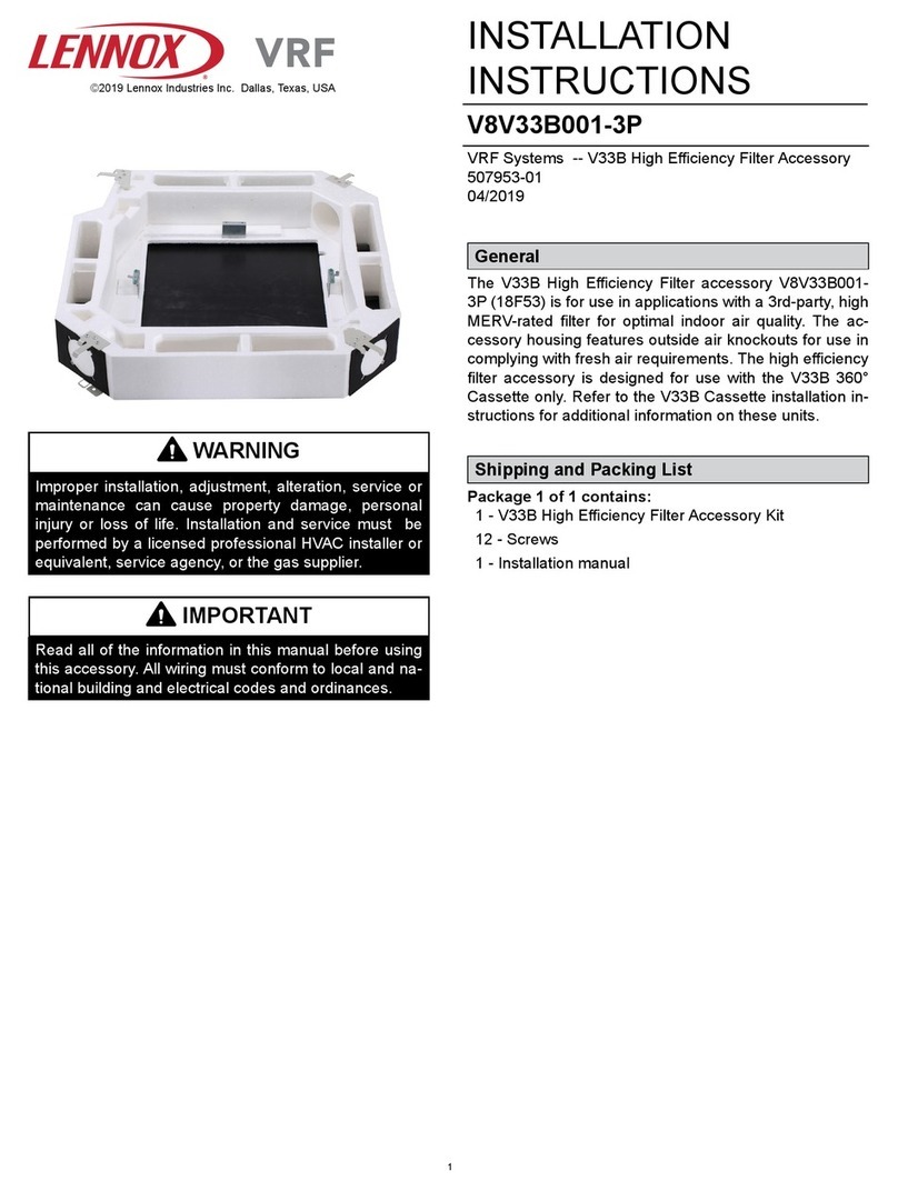
Lennox Enlight LGT Series User manual

Page 1
UNIT INFORMATIONUNIT INFORMATION
Service Literature
WARNING
To prevent serious injury or death:
1- Lock-out/tag-out before performing maintenance.
2- If system power is required (e.g., smoke detector
maintenance), disable power to blower, remove
fan belt where applicable, and ensure all
controllers and thermostats are set to the “OFF”
position before performing maintenance.
3- Always keep hands, hair, clothing, jewelry, tools,
etc., away from moving parts.
WARNING
Improper installation, adjustment, alteration,
service or maintenance can cause property damage,
personal injury or loss of life. Installation and service
must be performed by a licensed professional HVAC
installer or equivalent, service agency, or the gas
supplier
Table of Contents
Options / Accessories . . . . . . . . . . . . . . . . . . . . . Page 2
Unit Parts Arrangement . . . . . . . . . . . . . . . . . . . Page 18
I-Unit Components . . . . . . . . . . . . . . . . . . . . . . . Page 18
options.
-
-
-
-
stages.
-
-
-
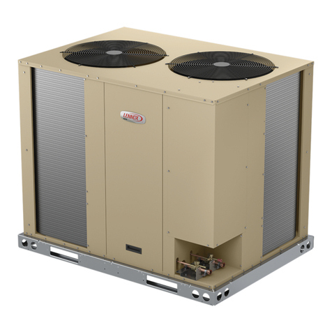
LGT SERIES
13 to 25 ton
45.7 to 88 kW
LGT156 through 300

Page 2
OPTIONS / ACCESSORIES
Item Description Catalog
Number
Unit Model No
156 180 210 240 300
COOLING SYSTEM
PVC 22H54 XXXXX
Copper 76W27 XXXXX
21Z07 OX OX OX OX OX
HEATING SYSTEM
Bottom Gas Piping Kit 85M31 XXXXX
89L97 XXXXX
Factory O O O
Factory O O O O O
Factory O O O O O
Factory O O O O
22H58 XXXXX
22H59 XXXXX
22V43 XXXXX
14N28 XXX
14N28 XXXXX
14N29 XXXXX
14N30 XXXX
Factory O O O O O
42W16 XXXXX
BLOWER - SUPPLY AIR
Factory O O O O O
MSAV Factory O O O O O
Motors Factory O O O
Factory O O O O O
Factory O O O O
Factory O O
Factory O O O
Factory O O O
Factory O O O O O
Factory O O O O O
Factory O O O O O
Factory O O O O
Factory O O O O
Factory O O O O
Factory O O
Factory O O
24B80 XXXXX
CABINET
23U69 OX
23U71 OX OX OX OX
Corrosion Protection Factory O O O O O

OPTIONS / ACCESSORIES
Item Description Catalog
Number
Unit Model No
156 180 210 240 300
CONTROLS
21Z10 OX OX OX OX OX
CPC Einstein Integration Factory O O O O O
54W27 OX OX OX OX OX
Novar Factory O O O O O
53W68 OX OX OX OX OX
21Z08 OX OX OX OX OX
22H56 OX OX OX OX OX
22H57 OX OX OX OX OX
INDOOR AIR QUALITY
Air Filters
MERV 8 54W67 OX OX OX OX OX
52W40 OX OX OX OX OX
21U42 XXXXX
44N61 XXXXX
77N39 XXXXX
23V86 XXXXX
87N52 XXXXX
87N54 XXXXX
CO 85L43 XXXXX
77N3990N43 XXXXX
Needlepoint Bipolar Ionization (NPBI)
21U37 XXX
21U38 X
21U39 X
UVC Germicidal Light Kit
1 21A94 XXXXX
10H20 XXXXX
10H21 XXXXX
ELECTRICAL
Factory O O O O O
Factory O O O O O
Factory O O O O O
Factory O O O O O
Factory O O O O O
54W88 OX OX OX OX OX
54W89 OX OX OX OX OX
90W82 OX
GFI Service
74M70 OX OX OX OX OX
³ Factory O O O O O
67E01 OX OX OX OX OX
Factory O O O O O
10C89 XXXXX
Factory O O O O O
1
2

OPTIONS / ACCESSORIES
Item Description Catalog
Number
Unit Model No
156 180 210 240 300
ECONOMIZER
22J18 OX OX OX OX OX
Economizer Controls
21Z09 OX OX OX OX OX
Factory O O O O O
21Z09 OX OX OX OX OX
Factory O O O O O
13J77 XXXXX
13J76 XXXXX
Barometric Relief Dampers With Exhaust Hood
54W78 OX OX OX OX OX
16K99 XXXXX
OUTDOOR AIR
Outdoor Air Dampers With Outdoor Air Hood
22J27 OX OX OX OX OX
13U05 XXXXX
¹ POWER EXHAUST (DOWNFLOW APPLICATIONS ONLY)
22H90 OX OX OX OX OX
22H91 OX OX OX OX OX
22V34 OX OX OX OX OX
HUMIDITROL®CONDENSER REHEAT OPTION (MSAV®) MODELS ONLY
Factory O O O O O
17M50 XXXXX
1

OPTIONS / ACCESSORIES
Item Description Catalog
Number
Unit Model No
156 180 210 240 300
ROOF CURBS
11F58 XXXXX
11F59 XXXXX
11F60 XXXXX
11F61 XXXXX
Adjustable Pitch Curb
43W26 XXXXX
Standard Roof Curbs, Horizontal - Requires Horizontal Return Air Panel Kit
11T89 XXXX
11T90 X
11T96 XXXX
11T97 X
Insulation Kit For Standard Horizontal Roof Curbs
73K32 XXXX
73K33 X
73K34 XXXX
73K35 X
Horizontal Return Air Panel Kit
87M00 XXXXX
CEILING DIFFUSERS
13K63 X X
13K64 XXX
13K58 X X
13K59 XXX
12X68 X X
12X70 XXX

SPECIFICATIONS 13 TON
General Data Nominal Tonnage 13 Ton 13 Ton
Model Number LGT156H4M LGT156H4V
High High
Blower Type MSAV
VAV
Cooling
Performance
1
1
1
1
Refrigerant
Charge
- - -
- - -
Gas Heating Options Available
Compressor Type (number)
Outdoor Coils
1 1
Outdoor Coil
Fans
Motor Type
Motor rpm
Indoor Coils
2Indoor
Blower
and
Drive
Selection
Filters
Electrical characteristics
1
2

SPECIFICATIONS 15 TON
General Data Nominal Tonnage 15 Ton 15 Ton
Model Number LGT180H4M LGT180H4V
High High
Blower Type MSAV
VAV
Cooling
Performance
1
1
1
Refrigerant
Charge
- - -
- - -
- - -
Gas Heating Options Available
Compressor Type (number)
Outdoor Coils
1 1
Outdoor Coil
Fans
Motor Type
Motor rpm
Indoor Coils
2Indoor
Blower
and
Drive
Selection
Filters
Electrical characteristics
1
2

Page 8
SPECIFICATIONS 17.5 TON
General Data Nominal Tonnage 17.5 Ton 17.5 Ton
Model Number LGT210H4M LGT210H4V
High High
Blower Type MSAV
VAV
Cooling
Performance
1
1
1
Refrigerant
Charge
- - -
- - -
- - -
- - -
Gas Heating Options Available
Compressor Type (number)
Outdoor Coils
11
Outdoor Coil
Fans
Motor Type
Motor rpm
Indoor Coils
2Indoor
Blower
and
Drive
Selection
Filters
Electrical characteristics
1
2

SPECIFICATIONS 20 TON
General Data Nominal Tonnage 20 Ton 20 Ton
Model Number LGT240H4M LGT240H4V
High High
Blower Type MSAV
VAV
Cooling
Performance
1
1
1
Refrigerant
Charge
- - -
- - -
- - -
- - -
Gas Heating Options Available
Compressor Type (number)
Outdoor Coils
1 1
Outdoor Coil
Fans
Motor Type
Motor rpm
Indoor Coils
2Indoor
Blower
and
Drive
Selection
Filters
Electrical characteristics
1
2

SPECIFICATIONS 25 TON
General Data Nominal Tonnage 25 Ton 25 Ton
Model Number LGT300S4M LGT300S4V
Standard Standard
Blower Type MSAV
VAV
Cooling
Performance
1
1
1
Refrigerant
Charge
- - -
- - -
- - -
- - -
Gas Heating Options Available
Compressor Type (number)
Outdoor Coils
1 1
Outdoor Coil
Fans
Motor Type
Motor rpm
Indoor Coils
2Indoor
Blower
and
Drive
Selection
Filters
Electrical characteristics
1
2

Page 11
SPECIFICATIONS GAS HEAT
Usage Data Model Number LGT156
LGT180
LGT210
LGT156
LGT180
LGT210
LGT240
LGT300
LGT180
LGT210
LGT240
LGT300
Low (L) Standard (S) Medium (M) High (H)
One
¹ Gas Heating
Performance
First Stage
- - -
- - -
- - -
First Stage - - - - - - - - -
- - - - - - - - - - - -
- - - - - - - - - - - -
- - -
First Stage
- - - - - - - - - - - -
1 in. NPT 1 in. NPT 1 in. NPT 1 in. NPT
11 11 11 11
1
HIGH ALTITUDE DERATE
NOTE - Units may be installed at altitudes up to 2000 feet above sea level without any modication.
At altitudes above 2000 feet, units must be derated to match gas manifold pressures shown
in table below.
At altitudes above 4500 feet units must be derated 4% for each 1000 feet above sea level.
NOTE − This is the only permissible derate for these units.
Refer to the Installation Instructions for more detailed information.
ONE STAGE HEAT
No Adjustment Required
TWO STAGE HEAT
Heat Input Type Altitude Feet Gas Manifold Pressure - in. w.g. Input Rate (Btuh)
Natural Gas LPG/Propane Gas First Stage Second Stage
FOUR STAGE HEAT
¹ Heat Input Type Altitude Feet
Gas Manifold Pressure - in. w.g. Input Rate (Btuh)
Natural Gas LPG/Propane Gas First
Stage
Second
Stage
Third
Stage
Fourth
Stage
1

Page 12
BLOWER DATA
Air Volume
cfm
TOTAL STATIC PRESSURE - Inches Water Gauge (Pa)
0.20 0.40 0.60 0.80 1.00 1.20 1.40 1.60 1.80 2.00 2.20 2.40 2.60
RPM BHP RPM BHP RPM BHP RPM BHP RPM BHP RPM BHP RPM BHP RPM BHP RPM BHP RPM BHP RPM BHP RPM BHP RPM BHP
- - - - - - - - - - - - - - - - - - - - - - - - - - - - - - - - - - - - - - - - - -
- - - - - - - - - - - - - - - - - - - - - - - - - - - - - - - - - - - -
- - - - - - - - - - - - - - - - - - - - - - - - - - - - - -
- - - - - - - - - - - - - - - - - - - - - - - -
- - - - - - - - - - - -
- - - - - -
- - - - - - - - - - - -
- - - - - - - - - - - -
- - - - - - - - - - - - - - - - - -
- - - - - - - - - - - - - - - - - - - - - - - -
- - - - - - - - - - - - - - - - - - - - - - - -
- - - - - - - - - - - - - - - - - - - - - - - - - - - - - -
- - - - - - - - - - - - - - - - - - - - - - - - - - - - - - - - - - - -
- - - - - - - - - - - - - - - - - - - - - - - - - - - - - - - - - - - -
- - - - - - - - - - - - - - - - - - - - - - - - - - - - - - - - - - - - - - - - - -

BLOWER DATA
FACTORY INSTALLED BELT DRIVE KIT SPECIFICATIONS
Nominal
hp
Maximum
hp
Drive Kit Number RPM Range
1
2
8
11
FACTORY INSTALLED OPTIONS/FIELD INSTALLED ACCESSORY AIR RESISTANCE
Air
Volume
cfm
Wet Indoor
Coil Humiditrol®
Reheat
Coil
Gas Heat Exchanger
Economizer Filters
Horizontal
Roof Curb
156,
180
210,
240,
300
Low/
Standard
Heat
Medium
Heat
High
Heat
156
thru
240
300
in. w.g. in. w.g. in. w.g. in. w.g. in. w.g. in. w.g. in. w.g. MERV 8 MERV 13 MERV 16 in. w.g. in. w.g.
- - - -
- - - -
- - -
- - -
- - -
- - -
- - -
- - -
- - - .11
.11 - - - .12
.12 - - - .12
- - -
.11 - - - .11
.12 - - - .11
.12 .12
.18
.11 .18
.12 .21 .11
.11 .21
.12 .11 .22 .21
.11
.18 .12
.12 .21
.22 .22
.11 .18

POWER EXHAUST FAN PERFORMANCE
Return Air System Static Pressure Air Volume Exhausted
in. w.g. cfm
CEILING DIFFUSER AIR RESISTANCE - in. w.g.
Air
Volume
cfm
RTD11-185S RTD11-275S
FD11-185S FD11-275S
2 Ends Open 1 Side/2 Ends
Open
All Ends &
Sides Open 2 Ends Open 1 Side/2 Ends
Open
All Ends &
Sides Open
- - - - - - - - - - - -
- - - - - - - - - - - -
- - - - - - - - - - - -
- - - - - - - - - - - -
- - - - - - - - - - - -
- - - - - - - - - - - -
- - - - - - - - - - - -
- - - - - - - - - - - -
- - - - - - - - - - - -
- - - - - - - - - - - -
- - - - - - - - - - - -
- - - - - - - - - - - -
- - - - - - - - - - - -
.88 - - - - - - - - - - - -
- - - - - - - - - - - -
- - - - - - - - - - - -
- - - - - - - - - - - -
- - - - - - - - - - - -
- - - - - - - - - - - - .81
- - - - - - - - - - - -
- - - - - - - - - 1.21 .88 - - -
CEILING DIFFUSER AIR THROW DATA - ft.
Model
No.
Air Volume
cfm
1 Model
No.
Air Volume
cfm
1
RTD11-185S
Step-Down
FD11-185S
Flush
RTD11-275S
Step-Down
FD11-275S
Flush
1
open.
BLOWER DATA

ELECTRICAL DATA 13 TON
Model No. LGT156H4
1Voltage - 60Hz 208/230V - 3 Ph 460V - 3 Ph 575V - 3 Ph
Compressor 1
Compressor 2
2.8 1.1
1
2
1
2
Motor
2
28
ELECTRICAL DATA 15 TON
Model No. LGT180H4
1Voltage - 60Hz 208/230V - 3 Ph 460V - 3 Ph 575V - 3 Ph
Compressor 1
Compressor 2
2.8 1.1
2.8 2.2
1
2
1
2
Motor
11
2
28
88 28
1
2

ELECTRICAL DATA 17.5 TON
Model No. LGT210H4
1Voltage - 60Hz 208/230V - 3 Ph 460V - 3 Ph 575V - 3 Ph
Compressor 1
Compressor 2
2.8 1.1
2.8 2.2
1
2
1
2
Motor
11
2
ELECTRICAL DATA 20 TON
Model No. LGT240H4
1Voltage - 60Hz 208/230V - 3 Ph 460V - 3 Ph 575V - 3 Ph
Compressor 1
Compressor 2
2.8 1.1
2.8 2.2
1
1
2
Motor
11 11
2
1
2

ELECTRICAL DATA 25 TON
Model No. LGT300S4
1Voltage - 60Hz 208/230V - 3 Ph 460V - 3 Ph 575V - 3 Ph
Compressor 1
8.2
Compressor 2
8.2
2.8 1.1
2.8 2.2
1
1
2
Motor
11 11
2
1
2

Page 18
PARTS ARRANGEMENT
8.8.8.8
EVAPORATOR
COIL
COMBUSTION
AIR INDUCER
CONDENSER FANS
(3 ON 156,
4 ON 180, 210
6 on 240, 300)
CONDENSER
COILS
COMPRESSORS
(2 ON 156 - 1 & 3;
3 ON 180 - 1, 2, & 3
4 on 210, 240, & 300)
GAS VALVE BURNERS
FILTERS
(SIX - 24 X 24 X 2”)
DISCONNECT
(FACTORY-INSTALLED
OPTION)
REHEAT
COIL
BLOWERS
BLOWER
MOTOR
ECONOMIZER
DAMPERS
(OPTIONAL)
CONDENSATE
DRAIN
BLOWER
INVERTER
UNIT
CONTROLLER
12
3
4
FIGURE 1
I-UNIT COMPONENTS
-
-
CAUTION
As with any mechanical equipment, contact with
sharp sheet metal edges can result in personal
injury. Take care while handling this equipment and
wear gloves and protective clothing.
ELECTROSTATIC DISCHARGE (ESD)
Precautions and Procedures
CAUTION
electronic components. Take precautions
to neutralize electrostatic charge by
touching your hand and tools to metal
prior to handling the control.
A-Control Box Components
-
sor compartment.
1-Disconnect Switch S48
-
.
2-Control Transformer T1
-
-
-
BLUE YELLOW
ORANGE
RED
BLACK
230 VOLTS
208 VOLTS
PRIMARY
SECONDARY
208/230V TRANSFORMER
FIGURE 2
3-Contactor Transformer T18

Components Arrangement
FIGURE 3
Components Arrangement
FIGURE 4

4-Terminal Block TB13
5-Outdoor Fan Motor Fuse Block & Fuses
-
6-Compressor Contactor K1, K2, K14, K146
-
7-Blower Contactor K3
-
-
-
8-Ultraviolet Germicidal Lamp (UVC)
-
9-Burner Controls A3 & A12
-
-
-
10-Power Exhaust Relay K65 & K231 (PED units)
11-Variable Frequency Drive A96 (optional)
-
12-VFD Power To Motor Contactor K202 (optional)
13-Inverter Start Forward Rotation Relay K203 (op-
tional)
14-Unit Controller A55
-
-
15-Compressor 3 & 4 Controller
-
-
-
-
ings.
This manual suits for next models
15
Table of contents
Other Lennox Fan manuals

Lennox
Lennox ARIA EC Series User guide

Lennox
Lennox FLATAIR KFC Series User manual

Lennox
Lennox 92W76 User manual

Lennox
Lennox V8V33B001-3P User manual

Lennox
Lennox KG Series User manual

Lennox
Lennox EvenHeater ECB29EH User manual

Lennox
Lennox ELS SERIES Installation and operation manual

Lennox
Lennox COMFAIR HH Series User guide

Lennox
Lennox LPVK-110 User manual

Lennox
Lennox 18M7901 User manual